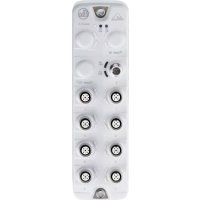
AC2951 - Power Strip IFM - Free user manual and instructions
Find the device manual for free AC2951 IFM in PDF.


User questions about AC2951 IFM
0 question about this device. Answer the ones you know or ask your own.
Ask a new question about this device
Download the instructions for your Power Strip in PDF format for free! Find your manual AC2951 - IFM and take your electronic device back in hand. On this page are published all the documents necessary for the use of your device. AC2951 by IFM.
USER MANUAL AC2951 IFM
Operating instructions
Passive power distributor
Process
Line
AC295x
Contents
1 Preliminary note 3
1.1 Symbols used 3
1.2 Warnings used 3
2 Safety instructions.... 4
3 Intended use.... 5
3.1 Safety symbol on the device 5
4 Installation.... 6
4.1 Install device.... 6
5 Electrical connection.... 7
5.1 UL applications 7
5.2 Wiring 7
5.3 Voltage supply / fuse.... 8
6 Operating and display elements 9
7 Scale drawing 10
8 Maintenance, repair and disposal 11
1 Preliminary note
You will find instructions, technical data, approvals, accessories and further information using the QR code on the unit / packaging or at www.ifm.com.
1.1 Symbols used
√ Requirement
Instructions
Reaction, result
[...] Designation of keys, buttons or indications
→ Cross-reference

Important note
Non-compliance may result in malfunction or interference.

Information
Supplementary note
1.2 Warnings used
ATTENTION
Warning of damage to property

CAUTION
Warning of personal injury
▷ Slight reversible injuries may result.

WARNING
Warning of serious personal injury
▷ Death or serious irreversible injuries may result.
2 Safety instructions
- The unit described is a subcomponent for integration into a system.
- The system architect is responsible for the safety of the system.
The system architect undertakes to perform a risk assessment and to create documentation in accordance with legal and normative requirements to be provided to the operator and user of the system. This documentation must contain all necessary information and safety instructions for the operator, the user and, if applicable, for any service personnel authorised by the architect of the system.
- Read this document before setting up the product and keep it during the entire service life.
- The product must be suitable for the corresponding applications and environmental conditions without any restrictions.
- Only use the product for its intended purpose (→ Intended use).
- If the operating instructions or the technical data are not adhered to, personal injury and/or damage to property may occur.
- In case of malfunctions of the unit, please contact the manufacturer. Tampering with the unit is not allowed.
• Installation, electrical connection, set-up, programming, configuration, operation and maintenance of the product must be carried out by personnel qualified and authorised for the respective activity. - Protect units, connectors and cables against damage.
- Replace damaged units, otherwise the technical data and safety will be impaired.
3 Intended use
The passive Process
Line power distributor can be used to supply IO-Link masters or AS-i modules and intelligent sensors/actuators.
Each supply connection (AS-i operation: AS-i / AUX; IO-Link operation: US / UA) has overcurrent detection (no shutdown).
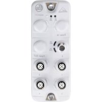
• AC2950: 4-port power distributor
• AC2951: 8-port power distributor

The device is designed for use without a control cabinet in the food industry (indoor use).
The impedance of the power distributor corresponds to that of a standard slave in the AS-i network.
▶ Only use the unit within the limits of the technical data.
3.1 Safety symbol on the device
Safety symbol on the device:
▶ Adhere to the operating instructions for the safe operation of the unit.
4 Installation
4.1 Install device

▶ Disconnect the power to the machine during installation.
▶ Use a flat mounting surface for installation.
▶ Fix the unit to the mounting surface using 2 M5 mounting screws and washers, max. tightening torque 1.8 Nm.
5 Electrical connection
The device must be connected by a qualified electrician.
Observe the national and international regulations for the installation of electrical equipment.
Disconnect power.
Voltage supply according to SELV / PELV.
The IP rating of the overall system depends on the protection ratings of the individual devices, the applied connection elements and the corresponding protective caps.
The M12 connection parts in the device comply with the ingress resistance requirements of the standard EN61076-2-101. To adhere to the protection rating, only cables certified to this standard must be used. The system architect undertakes to ensure the ingress resistance of cables they have cut to length.
- Recommended maximum cable length: 5 m (AS-i operation)
- Recommended maximum cable length: 20 m (IO-Link operation)
Fasten the cable with a tightening torque of 0.6...0.8 Nm, observe the cable manufacturer's specifications.
▶ Carry out the fitting according to the indications of the cable manufacturer, a max. tightening torque of 0.8 Nm is permissible.
▶ During installation, place the M12 connector vertically so that the coupling nut will not damage the thread.
▶ Provide cables with a strain relief depending on the mounting conditions to avoid excessive strain on the installation points and the M12 connections.
▶ Ensure correct fit and proper assembly of the M12 connection parts. If these instructions are not complied with, the specified protection rating cannot be guaranteed.
▶ To connect the device, use M12 connectors with protection rating IP 65 / IP 66 / IP 67 or higher, depending on the requirements of the application.
▶ Use M12 connectors with gold-plated contacts.
▶ Cover the unused sockets with M12 protective caps, tightening torque 0.6...0.8 Nm.

In case of cables that are longer than 20 m (IO-Link operation), take the voltage drop and the necessary minimum supply voltage of 20 V into consideration.
5.1 UL applications
To connect devices, only use UL-certified cables belonging to category CYJV or PVVA with a minimum temperature of 80 °C (75 °C in case of a maximum ambient temperature of 40 °C).
5.2 Wiring
Voltage supply Power IN 0 (voltage input)
| IO-Link operation | M12 connector(4 poles, A-coded) | AS-i operation |
| 1: + 24 V DC (US) |  | 1: AS-i + |
| 2: GND (UA) | 2: AUX - | |
| 3: GND (US) | 3: AS-i - | |
| 4: + 24 V DC (UA) | 4: AUX + |
Voltage supply Power OUT 1...4 (AC2950) / 1...8 (AC2951) (voltage output)
| IO-Link operation | M12 socket(4/5 poles, A-coded) | AS-i operation |
| 1: + 24 V DC (US) |  | 1: AS-i + |
| 2: GND (UA) | 2: AUX - | |
| 3: GND (US) | 3: AS-i - | |
| 4: + 24 V DC (UA) | 4: AUX + | |
| 5: n.c. | 5: n.c. |
5.3 Voltage supply / fuse
Observe the maximum current rating of the M12 connections ( → tech. data)
ATTENTION
No current limitation within the unit.
▷ If the M12 connectors are overloaded (overcurrent), damage to the unit or fire is possible.
▷ Each supply connection AS-i + / AUX + (AS-i operation) or + 24 V DC (US) / + 24 V DC (UA) (IO-Link operation) must be limited to the values of the technical data (current consumption) by external measures.
▶ Device protected.
6 Operating and display elements

Fig. 1: LED assignment
| LED US / AS-i green: | US / AS-i voltage supply ok |
| LED UA / AUX green: | UA / AUX voltage supply ok |
| LED FLT US / AS-i flashes red: | US / AS-i voltage output overloaded (overcurrent detected) |
| LED FLT UA / AUX flashes red: | UA / AUX voltage output overloaded (overcurrent detected) |
7 Scale drawing

Fig. 2: AC2950: 4-port power distributor
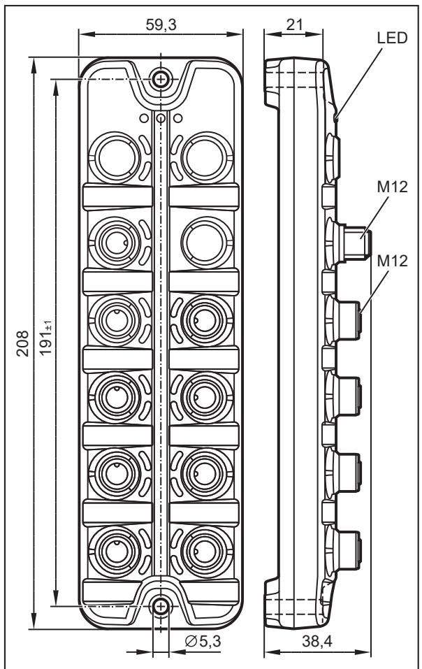
Fig. 3: AC2951: 8-port power distributor
8 Maintenance, repair and disposal
The operation of the unit is maintenance-free.
Only the manufacturer is allowed to repair the unit.
▶ After use dispose of the device in an environmentally friendly way in accordance with the applicable national regulations.
Cleaning the unit:
▶ Disconnect the unit from the voltage supply.
▶ Clean the unit from dirt using a soft, chemically untreated and dry micro-fibre cloth.
- 1 PRELIMINARY NOTE
- 1.1 SYMBOLS USED
- 1.2 WARNINGS USED
- 2 SAFETY INSTRUCTIONS
- 3 INTENDED USE
- 3.1 SAFETY SYMBOL ON THE DEVICE
- 4 INSTALLATION
- 4.1 INSTALL DEVICE
- 5 ELECTRICAL CONNECTION
- 5.1 UL APPLICATIONS
- 5.2 WIRING
- 5.3 VOLTAGE SUPPLY / FUSE
- 6 OPERATING AND DISPLAY ELEMENTS
- 7 SCALE DRAWING
- 8 MAINTENANCE, REPAIR AND DISPOSAL
Brand : IFM
Model : AC2951
Category : Power Strip