
CORPRO V W - Wardrobe Soler & Palau - Free user manual and instructions
Find the device manual for free CORPRO V W Soler & Palau in PDF.
| Product type | Vertical air curtain |
| Brand | Soler & Palau |
| Model | CORPRO V W (range) |
| Power supply | 230 V AC, 50 Hz |
| Control voltage | 12 V DC |
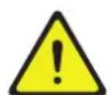
| Dimensions (COR-PRO-V2200 W) | W 340 x H 2200 x D 425 mm |
| Dimensions (COR-PRO-V2500 W) | W 340 x H 2500 x D 425 mm |
| Dimensions (COR-PRO-VL2200 W) | W 420 x H 2200 x D 522 mm |
| Dimensions (COR-PRO-VL2500 W) | W 420 x H 2500 x D 522 mm |
| Weight | 90 to 115 kg depending on model |
| Maximum blowing height | 2.5 m (standard models) / 3 m (VL models) |
| Hydraulic connection | 3/4" DN20 or 1" DN25 depending on model |
| Filtration | Class G3 (EU3) |
| Protection rating | IP20 |
| Ambient temperature range | 5 to 40 °C |
| Maximum water temperature | 90 °C |
| Maximum water pressure | 1.6 MPa |
| Control type | Remote touch Ditronic with display |
| Main functions | Air barrier, thermal protection, weekly programming, automatic mode, door contact, Modbus communication |
| Maintenance | Quarterly cleaning of grilles and filters, check of fastenings |
| Safety | Anti-freeze protection (AFP), stop by door contact, electrical disconnection before maintenance |
| Spare parts available | Filters (AFR CORPRO V W), RJ45/RJ11 cables |
Frequently Asked Questions - CORPRO V W Soler & Palau
User questions about CORPRO V W Soler & Palau
0 question about this device. Answer the ones you know or ask your own.
Ask a new question about this device
Download the instructions for your Wardrobe in PDF format for free! Find your manual CORPRO V W - Soler & Palau and take your electronic device back in hand. On this page are published all the documents necessary for the use of your device. CORPRO V W by Soler & Palau.
USER MANUAL CORPRO V W Soler & Palau
natural_image
Vertical cylindrical device with black insulation material, no visible text or symbols on the bodyESPAÑOL
ÍNDICE
- ESQUEMA ELÉCTRICO 4
- GENERALIDADES....5
- NORMAS DE SEGURIDAD Y MARCADO "CE" 5
- NORMAS GENERALES Y AVISO....5
- RECEPCIÓN, TRANSPORTE Y ALMACENAMIENTO....5
5.1. Recepción 5
5.2. Transporte 5
5.3. Almacenamiento....6
COR-PRO-V COR-PRO-VL
| COR-PRO-V2200 W 38 | COR-PRO-V2500 W 45 | COR-PRO-VL2200 W 50 | COR-PRO-VL2500 W 56 | ||||
| Altura máxima de descarga m | 2,5 2,5 3 3 | ||||||
| Dimensiones Largo D mm | 340 340 420 420 | ||||||
| Alto mm | 2200 2500 2200 2500 | ||||||
| Profundo | mm | 425 425 522 522 | |||||
| Peso | kg | 90 100 105 115 | |||||
| Conexión agua | NPS/DN | 34'' / 20 mm | 34'' / 20 mm | 1" / 25 mm | 1" / 25 mm | ||
natural_image
Simple 3D rendering of a vertical cylindrical object on a plain background (no text or symbols)natural_image
Simple 3D rendering of a blank white panel next to a black cylindrical object on a gray background (no text or symbols)natural_image
Red cylindrical object with a white top and perforated bottom, no visible text or symbols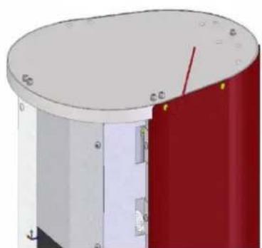
natural_image
3D rendering of a cylindrical mechanical component with red and white sections, no visible text or symbols
natural_image
Red cylindrical object with rounded ends and small protrusions, no visible text or symbolsnatural_image
Two identical 3D mechanical assembly diagrams showing a yellow bolt and nut on a curved base, with no visible text or symbols.
natural_image
Mechanical assembly diagram showing a cylindrical component with attached tubing and a yellow rod, mounted on a red base (no text or symbols visible)natural_image
Diagram of a device rear panel with green and red components, no visible text or symbolsnatural_image
3D cutaway view of a cylindrical electronic device showing internal components and wiring (no text or symbols visible)natural_image
Two abstract geometric symbols: a red circle with an arrow pointing right and a blue circle with an left-pointing arrow (no text or labels)Media input Media output

natural_image
Digital display device with a control panel and a 3D sensor or sensor unit (no visible text or symbols)11.3. AJUSTES BÁSICOS

natural_image
Three icons on a blue background: clock, watch, and gear (no text or symbols)

natural_image
Four gray icons on a blue background: folder, checkmark, hand, and watch symbol (no text or labels)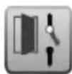


natural_image
Cross-sectional diagram of a cylindrical device with internal components, showing red and white sections (no text or symbols)- WIRING DIAGRAM 18
- INTRODUCTION....19
- SAFETY REGULATIONS AND "CE" MARKING....19
- GENERAL INSTRUCTIONS AND WARNING 19
- RECEPTION, TRANSPORTATION AND STORAGE 19
5.1. Reception....19
5.2. Transportation 19
5.3. Storage 20
- DESCRIPTION 20
6.1. Dimensions....20 - INSTALLATION....21
- ELECTRICAL CONNECTION 22
- HEATING DISTRIBUTION CONNECTION....23
-
COMMISSIONING 24
-
REMOTE CONTROL OPERATION (Ditronic)....24
11.1. Controller pictos symbology....25
11.2. Basic operation....26
11.3. Basic settings ...... 26
11.4. Advanced settings....28
- BASIC SERVICE INFORMATION AND MAINTENANCE 29
12.1. Quarterly maintenance....29
12.2. Cleaning and filter maintenance 30
- PUTTING OUT OF SERVICE AND RECYCLING 30
- MODBUS MAP 45
SYMBOL DESCRIPTION
Technical information Important information for your safety
Important information to read carefully as there is a risk of damaging the equipment by acting incorrectly

Important information, read carefully
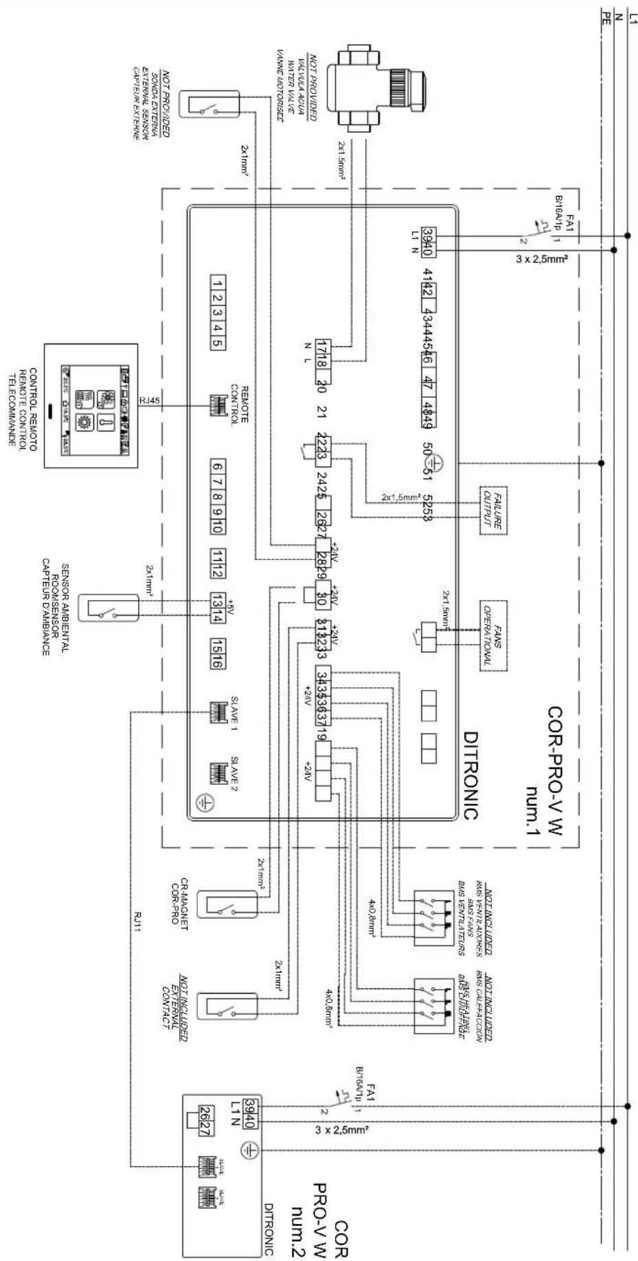
1. WIRING DIAGRAM
EN
flowchart
graph TD
    A["MINI"] --> B["3×2.5mm²"]
    C["MINI"] --> D["2×1.5mm²"]
    E["MINI"] --> F["3×2.5mm²"]
    G["MINI"] --> H["4×1.5mm²"]
    I["MINI"] --> J["5×2.5mm²"]
    K["MINI"] --> L["6×2.5mm²"]
    M["MINI"] --> N["7×2.5mm²"]
    O["MINI"] --> P["8×2.5mm²"]
    Q["MINI"] --> R["9×2.5mm²"]
    S["MINI"] --> T["10×2.5mm²"]
    U["MINI"] --> V["11×2.5mm²"]
    W["MINI"] --> X["12×2.5mm²"]
    Y["MINI"] --> Z["13×2.5mm²"]
    AA["MINI"] --> AB["14×2.5mm²"]
    AC["MINI"] --> AD["15×2.5mm²"]
    AE["MINI"] --> AF["16×2.5mm²"]
    AG["MINI"] --> AH["17×2.5mm²"]
    AI["MINI"] --> AJ["18×2.5mm²"]
    AK["MINI"] --> AL["19×2.5mm²"]
    AM["MINI"] --> AN["20×2.5mm²"]
    AO["MINI"] --> AP["21×2.5mm²"]
    AQ["MINI"] --> AR["22×2.5mm²"]
    AS["MINI"] --> AT["23×2.5mm²"]
    AU["MINI"] --> AV["24×2.5mm²"]
    AW["MINI"] --> AX["25×2.5mm²"]
    AY["FAT 1"] --> AZ["FAT1 3×2.5mm²"]
    BA["FAT 2"] --> BB["FAT2 3×2.5mm²"]
    BC["FAT3 3×2.5mm²"] --> BD["FAT4 3×2.5mm²"]
    BE["FAT5 3×2.5mm²"] --> BF["FAT6 3×2.5mm²"]
    BG["FAT7 3×2.5mm²"] --> BH["FAT8 3×2.5mm²"]
    BI["FAT9 3×2.5mm²"] --> BJ["FAT10 3×2.5mm²"]
    BK["FAT11 3×2.5mm²"] --> BL["FAT12 3×2.5mm²"]
    BM["FAT13 3×2.5mm²"] --> BN["FAT14 3×2.5mm²"]
    BO["FAT15 3×2.5mm²"] --> BP["FAT16 3×2.5mm²"]
    BZ["FAT17 3×2.5mm²"] --> CA["FAT18 3×2.5mm²"]
    CB["FAT19 3×2.5mm²"] --> CC["FAT20 3×2.5mm²"]
    DD["FAT21 3×2.5mm²"] --> EE["FAT22 3×2.5mm²"]
    FF["FAT23 3×2.5mm²"] --> AG["FAT24 3×2.5mm²"]
    AH["FAT25 3×2.5mm²"] --> AI["FAT26 3×2.5mm²"]
    AJ["FAT27 3×2.5mm²"] --> AK["FAT28 3×2.5mm²"]
    AL["FAT29 3×2.5mm²"] --> AM["FAT30 3×2.5mm²"]
    AN["FAT31 3×2.5mm²"] --> AO["FAT32 3×2.5mm²"]
    AP["FAT33 3×2.5mm²"] --> AQ["FAT34 3×2.5mm²"]
    AR["FAT35 3×2.5mm²"] --> AS["FAT36 3×2.5mm²"]
    AT["FAT37 3×2.5mm²"] --> AU["FAT38 3×2.5mm²"]
    AV["FAT39 3×2.5mm²"] --> AW["FAT40 3×2.5mm²"]
    AX["FAT41 3×2.5mm²"] --> AY["FAT42 3×2.5mm²"]
    AZ["FAT43 3×2.5mm²"] --> BA["FAT44 3×2.5mm²"]
    BB["FAT44 3×2.5mm²"] --> BC["FAT45 3×2.5mm²"]
    BD["FAT45 3×2.5mm²"] --> BD
    BE["FAT46 3×2.5mm²"] --> BD
    BF["FAT47 3×2.5mm²"] --> BG["FAT48 3×2.5mm²"]
    BH["FAT48 3×2.5mm²"] --> BH
    BI["FAT49 3×2.5mm²"] --> BJ
    BJ["FAT49 3×2.5mm²"] --> BK
    BL["FAT49 3×2.5mm²"] --> BL
    BG["FAT49 3×2.5mm²"] --> BL
    BH["FAT49 3×2.5mm²"] --> BH
    BI["FAT49 3×2.5mm²"] --> BI
    AD["FAT49 3×2.5mm²"] --> BJ
    AE["FAT49 3×2.5mm²"] --> BK
    AF["FAT49 3×2.5mm²"] --> BL
    BG["FAT49 3×2.5mm²"] --> BL
    BH["FAT49 3×2.5mm²"] --> BL
    BI["FAT49 3×2.5mm²"] --> BL
    AD["FAT49 3×2.5mm²"] --> BL
    AE["FAT49 3×2.5mm²"] --> BL
    BH["FAT49 3×2.5mm²"] --> BL
    BI["FAT49 3×2.5mm²"] --> BL
    AD["FAT49 3×2.5mm²"] --> BL
    AE["FAT49 3×2.5mm²"] --> BL
    BH["FAT49 3×2.6mm²"] --> BL
    BI["FAT49 3×2.6mm²"] --> BL
    AD["FAT49 3×2.6mm²"] --> BL
    AE["FAT49 3×2.6mm²"] --> BL
    BH["FAT49 3×2.6mm²"] --> BL
    BI["FAT49 3×2.6mm²"] --> BL
    AD["FAT49 3*6 mm*"]
2. INTRODUCTION
Thank you for purchasing this appliance. It has been manufactured in full compliance with applicable safety regulations and EU standards. Please read this instruction book carefully, as it contains important information for your safety during the installation, use and maintenance of this product. Keep it at hand for future reference.
Please check that the appliance is in perfect condition when you unpack it, as all factory defects are covered by the S&P guarantee. Also, check that the appliance is what you have requested and technical data in nameplate matches your needs.
3. SAFETY REGULATIONS AND "CE" MARKING
S&P technicians are firmly committed to research and development of ever more efficient products and in compliance with current safety regulations.

The instructions and recommendations given below reflect current regulations, principally regarding safety, and therefore are based on compliance with general regulations. Therefore, we recommend all people exposed to hazards to strictly follow the safety regulations in force in your country.
S&P will not be held liable for any possible harm or damage caused by noncompliance with the safety regulations, as well as caused by modifying the product. The CE mark and the corresponding declaration of conformity are proof of the product's conformity with current EU regulations.
4. GENERAL INSTRUCTIONS AND WARNING

A hazard analysis of the product has been carried out as provided in the Machine Directive. This document contains information for all personnel exposed to these hazards, with aim of preventing possible harm or damage due to faulty handling or maintenance.
All maintenance operations (ordinary and extraordinary) must be carried out with the machine switched off and the electrical power supply disconnected.
Before connecting the power supply cable to the terminal strip, make sure the mains voltage corresponds to the voltage indicated on the specifications nameplate of the unit.
COR-PRO V W air curtain has been designed to prevent heat and cold losses and improve filtration between two spaces. Any other use or application will be out of purpose for which air curtain was designed. The manufacturer will not be responsible of damages resulting from an inappropriate use. Read and follow this document before start up the air curtain.
Authorized and qualified professionals following local regulations must carry out both the hanging installation, the electrical connection and any repairs.
The manufacturer reserves the right to make any change without previous notice, due to marketing or production reasons.
5. RECEPTION, TRANSPORTATION AND STORAGE
5.1. RECEPTION

Check carefully delivery note content that is part of your delivery. Check all items listed into the delivery note with special attention to accessories that could not be part of the main equipment volume or not installed into the unit. Check that packaging received are complete and in good conditions. Otherwise, inform the carrier and record it on the delivery note document. Then, immediately inform the transport company or the manufacturer.
5.2. TRANSPORTATION

Observe the instructions on labels placed on the unit. During transportation the air curtain package must not be tilted or placed in a different position than recommended by the manufacturer. The packaging incorporate nameplates with serial number and product description to facilitate identification.
Equipment must be transported in the original packaging only. This packaging has been tested for a long time and other alternatives may damage the unit. Transport and handling must be done with appropriate capacity equipment.
These transportation equipment must be handled by qualify staff. For a safety handling of the air curtain, at least a minimum number of two people is required.
5.3.STORAGE

Allowable storage conditions: -10°C to 50°C , humidity concentration of 50 - 85% without condensation. Keep the original packaging and avoid damages to it until final installation.
6. DESCRIPTION

An air curtain is a machine designed to create a mechanical air barrier with the main purpose of counteracting the cold air introduction into an indoor warm environment. In summer, its utility will be protection against hot air introduction in cool or air conditioning spaces. COR-PRO V W series are not intended to operate in industrial environments.
Technical operating conditions

• Power supply: 230V AC 50 Hz
- Range of working ambient temperatures: 5-40°C
- IP degree: 20
• Maximum operating water temperature / pressure: 90°C / 1,6 MPa
- Filter quality: G3 (EU3)
• Equipment has been designed to convey clean air without aggressive chemical agents
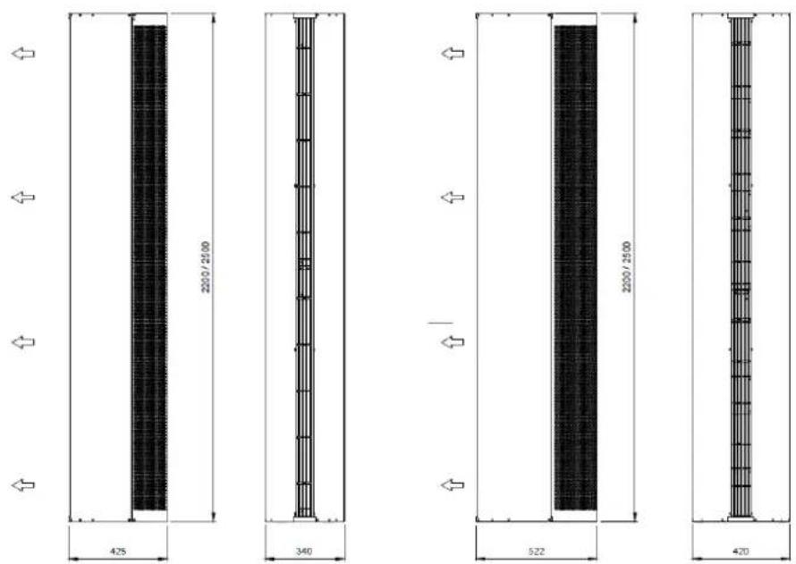
6.1. DIMENSIONS
General
| COR-PRO-V2200 W 38 | COR-PRO-V2500 W 45 | COR-PRO-VL2200 W 50 | COR-PRO-VL2500 W 56 | ||||
| Maximum air discharge length | m | 2,5 2,5 3 3 | |||||
| Dimensions Large D mm | 340 340 420 420 | ||||||
| High mm | 2200 2500 2200 2500 | ||||||
| Deep | mm | 425 425 522 522 | |||||
| Weight | kg | 90 100 105 115 | |||||
| Water connection | NPS/DN | 34" / 20 mm | 34" / 20 mm | 1" / 25 mm | 1" / 25 mm | ||
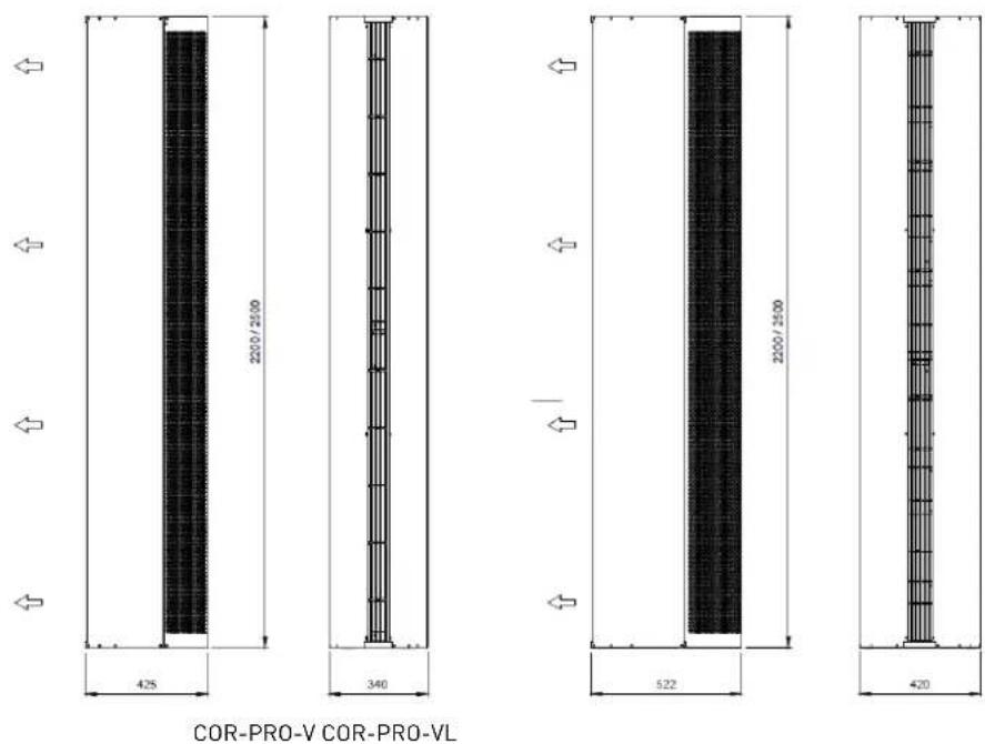
Installation distances
Lower base
Electrical and hydraulic connection on the lower face of the vertical air curtain.
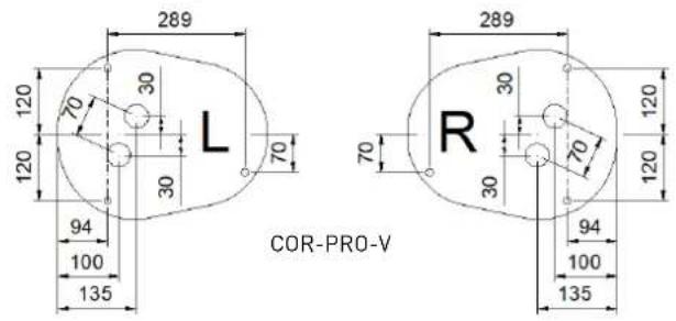
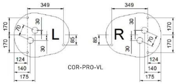
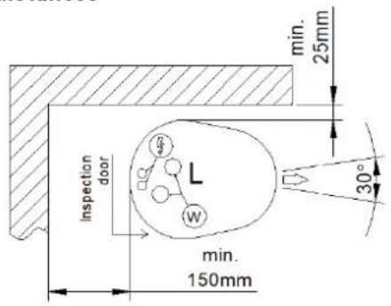
Location according to variant "L" or "R"
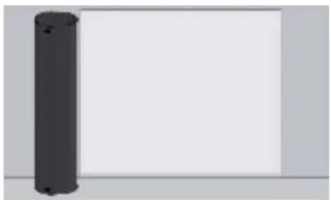
natural_image
Simple 3D rendering of a vertical cylindrical object on a plain background (no text or symbols)L - Left installation
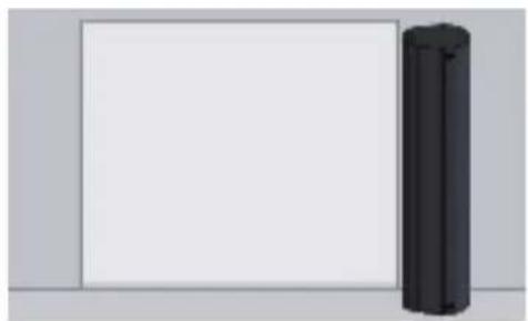
natural_image
Simple 3D rendering of a black cylindrical object on a plain white background (no text or symbols)R - Right installation
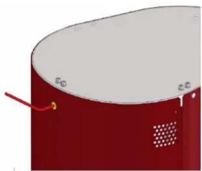
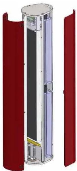
7. INSTALLATION

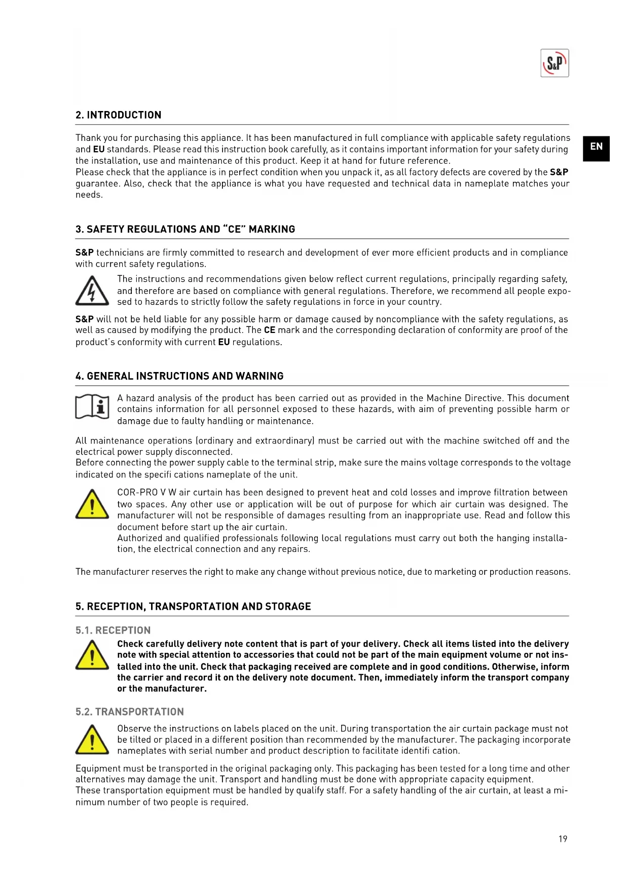
COR-PRO V W are air curtains designed for vertical operation connected to a hot water supply from the bottom of the unit. In the lower part of the air curtain there is a special structure so that it can be screwed to the ground. Access to this is possible once the suction grille has been removed together with inspection door. To do this, first remove the suction grille and then the inspection door.
natural_image
Red cylindrical object with a white top and perforated side, no visible text or symbols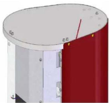
natural_image
3D rendering of a cylindrical mechanical component with red and white sections, no visible text or symbols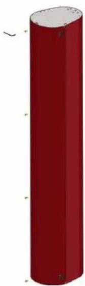
natural_image
Red cylindrical object with rounded ends and small protrusions, no visible text or symbols

During removing component process, take extreme precautions to avoid falling objects that could damage the curtain or injure the manipulator.
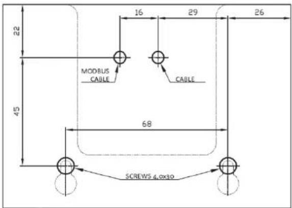
Following sketch below, prepare the installation site to anchor the air curtain to the ground. This must be finished and must not be under construction yet. Mark the anchor points and make the holes where the plugs and anchors will be placed. Check the absolute horizontality of the base. Pass all the electrical connection cables through the hole designed for this purpose and install the pipes for the water coil.
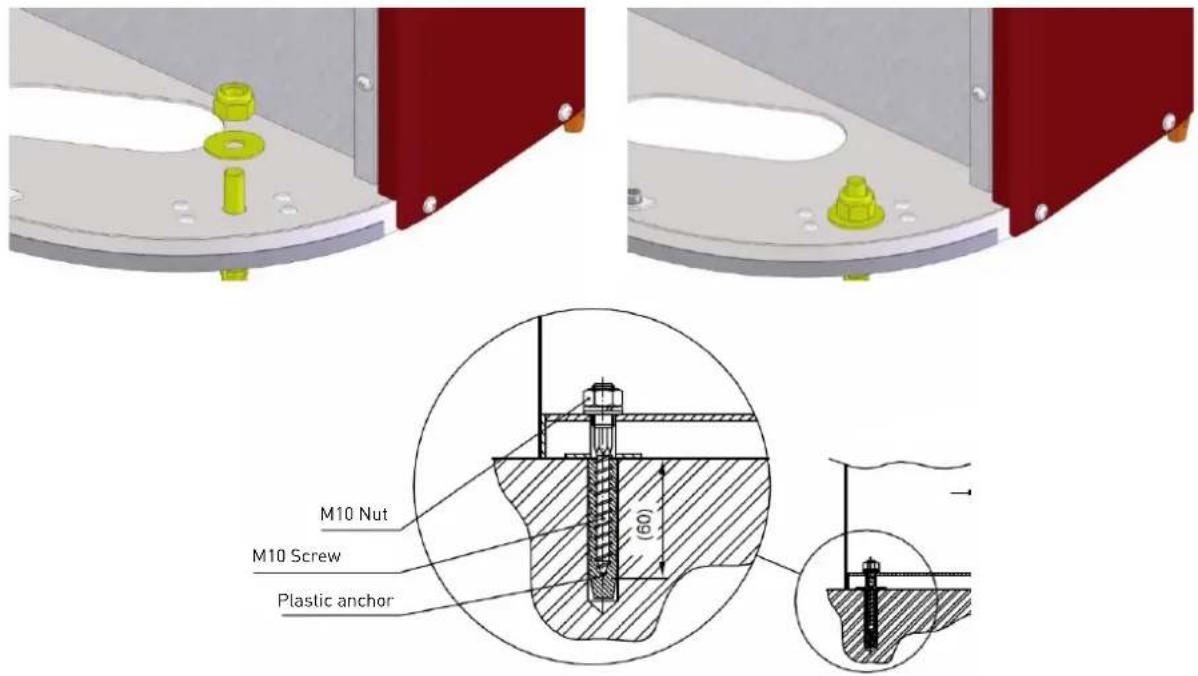

Plan lengths of electrical cables to reach the connection points located in the upper part of the curtain. Use only appropriate anchors, plugs and dowels. Carefully analyze the installation location and suitability of the anchors and fasteners used, as well as the strength of the structure. Always consider the capacity of the floor. The manufacturer is not responsible for failed caused by improper use of plugs, fasteners and/or suspension material.
It is recommended to use electrical wire gutter or similar to guide securely electrical cables in their vertical route to the upper terminal box.
Once the air curtain is installed, check the vertically and correct is necessary.
8. ELECTRICAL CONNECTION

Air curtain must be protected by its corresponding electrical protections depending on the electrical parameters of each model (see wiring diagram and/or nameplate). Connect cables to the terminals following mentioned wiring diagram, check connections, equipotential bonding and, finally, turn the power supply on. Use cables with adequate section for load requested.
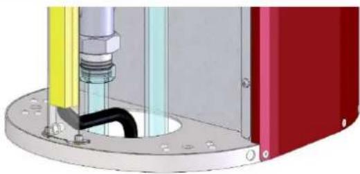
natural_image
Mechanical assembly diagram showing a pipe fitting with a black pipe inserted into a red housing (no text or symbols visible)Make sure that cables are not twisted or deformed. As shown in the image above, it is recommended to use an electrical wire gutter so that the electrical cables can run vertically through the air curtain in a safe way. Leave ends of individual cables free long enough for easy handling. Cut wires to a length that will allow them to reach the top of the unit. To access into connection terminals, you must first remove protective control cover.
natural_image
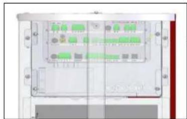
Interior view of a rectangular electronic device with multiple ports and connectors (no visible text or symbols)Control Unit - Terminal connections
Take into account general and specific local regulations. Unit must be disconnected from any power source when any task is done over it. Qualified personnel must only carry out all actions described and mentioned. After electrical connection, carefully check all terminals and carry out an initial test. Check correct FU fuses work from control unit.
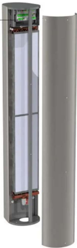
natural_image
3D cutaway view of a cylindrical electronic device showing internal components and casing (no text or symbols visible)9. HEATING DISTRIBUTION CONNECTION

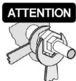
Check all hot water connections are in perfect condition before connecting heating distribution to the air curtain unit. Furthermore, please check hot transmission effect through components installed to ensure zero static, dynamic, and dilatation forces at input/output neck connections. No excessive force may be applied when connecting the hot water circuit to the air curtain's water coil exchanger. You will find a mark that notes use of two keys so that no stressing of the necks occurs in the course of tightening or loosening. When bolting and tightening up the screw union of the water coil must be secured by a clamp against undesired rotation that may subsequently result in deformations or damage to pipe necks on the heat exchanger. For this reason is highly recommended the use of fl exible connections between heating distribution duct installation and pipe necks.
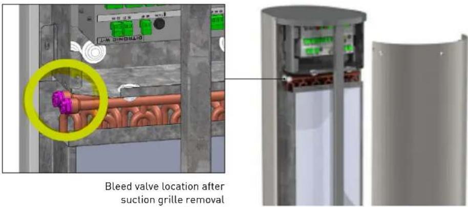
By default, connection tubes are located on the base of vertical air curtain and are accessible after removing inlet grille. Water input is identified by red mark with an arrow pointing inside and, output, by blue mark with arrow pointing outside.


Media input Media output

Do not swap inlet and outlet positions, this would cause drastic changes in water coil performance with consequent effects on the hydraulic system. Do not exceed the maximum admissible temperatures and pressures.
Purge the battery for proper operation and performance. Install shutoff valves in both pipes downstream of the unit. The connecting thread just above the air curtain must be removable and not fixed.


Pay attention to the cleanliness of the water circuit and, if the installation incorporates it, check the cleanliness of the upstream filter. Check the maximum temperature and pressure of the medium to avoid damage to the water coil. Install shutoff valves (not included) in both pipes downstream of the unit. The connecting thread just above the air curtain must be removable and not fixed. Purge the battery for a correct operation and performance.
10. COMMISSIONING
Before commissioning the unit, carry out following verifi cations:

• External casing integrity
- Ceiling or wall anchoring mounting
- Fixing filters and cleaning
- Correct connection and tightening of water pipes
- Correct water control valve installation (not included)
• Water pump operation (not included)
- Easy and direct access to inspection and maintenance door
• Supply voltage main presence
• Cables properly attached to their terminals
- Absence of mechanical objects or residues in inlet / outlet sides
11. REMOTE CONTROL OPERATION (Ditronic)

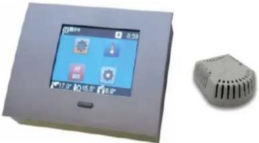
Remote control device is a touch screen type, for wall installation and it comes from factory with all COR-PRO V W models as default (on demand, special SM version without remote control for air curtain unit working as Slave). In addition, remote control packaging includes an Ambient/room temperature sensor that can be installed on the wall voluntarily if working in automatic mode, this room sensor is selected instead of discharge air temperature sensor (installed inside air curtain by default).
Remote control requires RJ45 cable between control device and air curtain (not included). The RJ45-10 COR-PRO accessory is offered as an option with a fixed length of 10m. In case of Master-Slave connection between two air curtains, cable required is RJ11 type (not included). The RJ 11-5 COR-PRO accessory is offered as an option with a fixed distance of 5m.
natural_image
Exterior view of a smart home control panel with display screen and 3D model of a device (no text or symbols visible)Technical operating conditions
• Power supply: 12V DC
• Maximum ambient working temperature: 35°C
- IP grade: 20
A wall fixing template is included in the packaging to facilitate wall installation together with necessary accessories for its anchorage.
11.1. CONTROLLER PICTOS SYMBOLOGY

Door contact enabled / Door status Filter maintenance alarm

Master - Slave Heat up mode active

Remote control active Component failure

BMS active External contact / remote control activ

Keyboard lock active Automatic mode activ

Sound ON Outlet air temperature

Anti-frost protection active Ambient/room


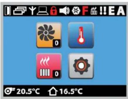
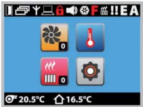
Main screen shows basic operating modes.

FAN
Manual selection of desired speed. After 1 second, value is stored automatically in memory.
TEMPERATURE SET POINT
Desired temperature selection depending on sensor selected (ambient/room sensor or outlet air temperature sensor).


HEATING
Manual selection of desired heating level. Electric heater will be active only if necessary based on temperature readings.

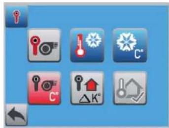
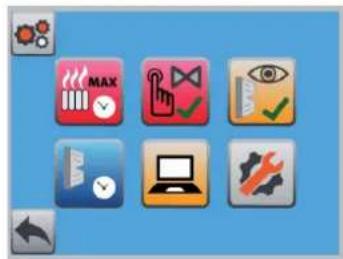
BASIC SETTINGS
Access to other adjustment parameters.
• Weekly programming
• Temperature parameters settings
- Reset factory settings
- Door contact adjustment
- Help button (disabled)
- Advanced settings (contact S&P)

11.3. BASIC SETTINGS

WEEKLY PROGRAMMING
Control allows air curtain operation depending on selected hour period. First, activate this function to program below.

natural_image
Three icons: clock, watch, and gear on a blue background (no text or symbols)
Weekday and real hour setting menu:

Day of the week

Hour

Minutes

Programming menu:
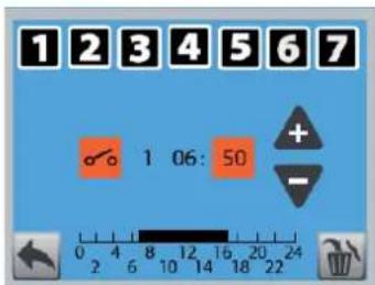

Day of the week

Starts program

Ends program
1 Program number

Hour

Minutes

TEMPERATURE PARAMETERS SETTINGS
Sensor type, summer/winter mode, anti-frost, minimum outlet temperature, sensor deviation correction and external sensor activation.


Temperature reference selection between outlet and room sensor.

Winter/Summer mode. If summer is selected, heating system is disabled even if there is a sudden temperature drop. Only anti-frost system will remain active.

Anti-frost protection. This system is normally used for water coil versions to avoid risk of freezing. If selected temperature is reached, the fault output relay is activated together with the activation of water valve (if installed, not included). If temperature continues dropping, the fans will stop working and an audible alarm will be activated and the logo will appear on the control display. In case of ambient sensor installed and enabled, take into account that control will automatically take into account the selected ambient temperature +3°C.
Minimum outlet temperature. Regardless all sensor values and setpoints, the air curtain will maintain this minimum air outlet temperature.
Sensor deviation correction. If sensor is installed in an inappropriate location for architectural or space reasons, readings offered can be corrected manually.
External sensor activation. Apart from displaying this value on the screen, you can also choose this parameter as a reference for automatic control.
DOOR CONTACT ADJUSTMENTS
Door contact activation, contact type parameterization and run-on-timer.
Door contact activation. With this function and through a door contact not included (accessory CR-MAGNET COR-PRO), it will be possible to see on the main screen of the control whether the door is opened or closed. Unless Automatic Mode A is active, the curtain will turn off with a delay once the door closes. The contact is a potential free type and maximum load is 24VDC/3A.
natural_image
Three gray square icons with icons on a blue background, no text or symbols present
Door contact position. Function that allows to define door contact as normally open or closed.


Run-on-timer when contact disconnection. Once the door contact detects that the door is closed, it initiates a recommended timing period to dissipate internal heat. It is recommended not to configure a value lower than the factory-set 60s. This function remains active only if the door contact function has been activated. If automatic mode A is active, this timing is disabled.
Door contact and control valve position. Function only for water coil versions. Selecting OFF, when the door is closed, ensures that the valve closes regardless of whether or not thermal support is required depending on the difference between the selected and measured temperatures. Selecting ON, when the door is closed, keeps the valve in position depending on the evaluation of the required controller temperature, that is, the valve is kept open (in case heating is requested from the controller temperature requirements set and temperatures measured in the sensor) or closed (if there is no need for thermal support according to selected and measured temperature).
11.4. ADVANCED SETTINGS


Access to advanced settings after entering code 100.

Keyboard mute.

Keyboard lock to prevent unauthorized manipulation. Once activated, the keyboard locks after 60 s.


Remote control activation by free voltage contact with maximum load 24VDC/3A. Once active, the remote control icon on the main screen will appear. If it blinks, it indicates that the contact has been interrupted.

Automatic A mode activation. Allows automatic operation depending on door contact (accessory). When door is closed and automatic A mode active, both heating and fans go to minimum levels as long as reading temperature is higher than set point temperature. Heating system will only be active when necessary according to measured and required temperature. As long as thermal support is not needed, fans will remain off. As default into automatic A mode, speed ratio will respond to: speed 1 if difference between measured and required temperature is less than 2°C; speed 2 is difference is between 3-5,5°C; speed 3 if between 6-9°C. If icon "A" on the main screen is illuminated, it indicates that automatic A mode is active. Door contact mode remains active when this operating mode is activated.

Filter maintenance interval. It allows resetting the countdown for filter maintenance (only for water coil versions)

Heating up mode activation. Pressing icon for 5 seconds activates a mode in which, during selected time (between 3-15 minutes), air curtain goes to maximum heating and fan speed performance to force a fast temperature increase. During selected period of maximum performance, if any button is pressed, the mode is interrupted going to previous configuration input.

Anti-frost protection (AFP) deactivation. Only for water coil air curtain versions.

Fan operation in anti-frost protection (AFP). Only for versions with a water coil. This function defines the behavior of the control when the AFP temperature is reached. If it is OFF, the valve is open and the fan is off. If it is ON, the valve will be open and the fan will run independently according to control settings. The function is active if the controller is not in AFP protection level 2. The AFP function never runs at level 2 to avoid a higher temperature drop. Recommendation: always select OFF if the air curtain is also used for heating (balances sudden thermal losses).

Lowest temperature record. The control can save the lowest temperature recorded by outlet temperature sensor (fitted as standard with all air curtains).

Manual valve test (only for versions with water coil). This function allows a manual test of the valve opening and closing without modifying the rest of control parameters.

Filter counter display enable (only for versions with water coil). This function activates operating hours counter for filter maintenance interval.

Filter maintenance interval settings (only for versions with water coil). Definition of the maintenance interval according to the hours of operation of the fans. The red "F" symbol appears on the main screen once the set time is exceeded. 20 hours before the limit is exceeded, a black "F" symbol will flash on the main display of the control.

External BMS upper control activation. Due to motor and control typology, it will only be possible to confi gure digital option. Once BMS upper control is activated, manual curtain control is disabled.
EN

Control with digital signals is carried out by combining three voltage-free contacts to control fans and three more to control electric heater. Pay attention to always combine at least one ventilation level when activating any heating level. See wiring diagram.

Modbus communication activation and configuration.
Special Modbus communication for specific countries.

Modbus Read level allows manual control by touch screen and, at the same time, visualization through Modbus network. See Modbus Map.
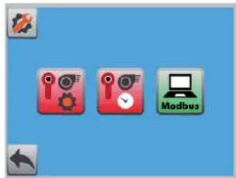


Access to specific parameters of Modbus network protocol. Avoid modifications except being a specialist in this fi eld.
12. BASIC SERVICE INFORMATION AND MAINTENANCE

All units have been carefully checked in Factory prior to shipment. That is why the most frequent error usually occur due to an incorrect understanding of equipment operation, wrong connections or incomplete wiring. Therefore, it is important to carefully follow all instructions to avoid difficult resolution problems. Such damage will not be covered by the warranty.
COR-PRO V W air curtains are made with components of proven quality and do not require special maintenance. However, to extend life expectancy of the equipment, we recommend that maintenance inspections be carried out at least at the specified intervals and always depending on their use.

Disconnect the equipment from power supply before carrying out any type of operation on it. There is a risk of electric shock.
12.1. QUARTERLY MAINTENANCE
- Check the integrity of suspension or anchoring elements together with tightening of connection elements.
- Complete cleaning of the inlet grille together with the discharge diffuser. Check the lightening of the fi xing screws.
- Check internal inlet "plenum" together with the water coil and remove any residue or object present. Use a vacuum cleaner to remove dust or steam to remove stuck dirt. If you use steam, do it with the lowest possible temperature and pressure. Also, always clean in the opposite direction to the airflow. Remove the air filter from the air curtain to avoid damaging it.
- Check if motor scroll and impeller are clean. Do not wash the motor with water and in any case wipe it with water and if necessary wipe it with a damp cloth to avoid damaging the motor winding. Do not start up the air curtain during next 60 minutes after cleaning to allow moisture to disappear. In case of cleaning blades, do not apply excessive strength as they could be damaged.
- Before winter, check the operation of anti-frost protection, the main circulation pump (not included) and the adjustment of the control valve (not included).
natural_image
Cross-sectional diagram of a cylindrical device with internal components, showing red and white sections (no text or symbols)- Check the tightness of the water coil together with the connection joints. If there is a filter in the water system before the air curtain, clean it and then check the operation of the coil.
- Check the safety of the unit regarding risks of electric shock in accordance with local applicable regulations together with grounding verification.
12.2. CLEANING AND FILTER MAINTENANCE

COR-PRO V W models incorporate air fi lters in the inlet side. This should be cleaned regularly to ensure the efficiency and performance of the air curtain. Cleanliness depends on the local conditions where the curtain is installed; it is recommended to check the fi lter and clean it once a month. A clogged fi lter does not represent a safety risk, but curtain performance may change and motor may suffer.
Filter removal:
- Remove the inlet grille.
- Release the filter by rotating the securing locks located on the sides of the filter.
- Remove the filter and clean dust particles. Replace the filter (accessory under description AFR COR-PRO-V W) if the blockage is evident even after cleaning of if filter material shows damage.

Only use original fi lters. Other air fi lters may have a quite different fi ltration class or pressure drop. This could provoke performance reduction or motor overheating causing failure hazard.
13. PUTTING OUT OF SERVICE AND RECYCLING
EEC legislation and our consideration of future generations mean that we should always recycle materials where possible; please do not forget to deposit all packaging in the appropriate recycling bins. If your device is also labeled with this symbol, please take it to the nearest Waste Management Plant at the end of its serviceable life.
FRANÇAIS
INDEX
- SCHÉMA DE CÂBLAGE....32
- INTRODUCTION....33
- RÈGLES DE SÉCURITÉ ET MARQUAGE "CE" 33
- INSTRUCTIONS GÉNÉRALES ET AVERTISSEMENT 33
- RECEPTION, TRANSPORT ET STOCKAGE 33
5.1. Reception....33
5.2. Transport 33
5.3. Stockage 34
- DESCRIPTION 34
6.1. Dimensions....34 - INSTALLATION....35
- CONNEXION ELECTRIQUE....36
- RACCORDEMENT HYDRAULIQUE DU CHAUFFAGE 37
-
MISE EN ROUTE 38
-
FONCTIONNEMENT DE LA COMMANDE TACTILE DEPORTÉE (Ditronic)....38
COR-PRO-V COR-PRO-VL
natural_image
Simple 3D rendering of a cylindrical object with a blank white space on the right side (no text or symbols)natural_image
Simple 3D rendering of a blank white panel next to a black cylindrical object on a gray background (no text or symbols)natural_image
Red cylindrical object with a white top and perforated bottom, no visible text or symbols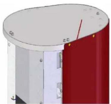
natural_image
3D rendering of a cylindrical mechanical component with red and white sections, showing mounting holes and a red arrow indicating direction (no text or symbols)
natural_image
Red cylindrical object with rounded ends and small protrusions, no visible text or symbols
natural_image
Mechanical assembly diagram showing a cylindrical component with attached tubing and colored components (no text or symbols visible)natural_image
Diagram of a server rack unit with multiple ports and indicator lights (no text or labels visible)natural_image
Cross-sectional diagram of a cylindrical device showing internal components and casing (no text or symbols)
natural_image
Two directional arrows, one red with a circular arrow and one blue with an arrowhead (no text or symbols)natural_image
3D rendered device with a touchscreen display and a small rectangular component (no visible text or symbols)Protection antigel active Temperature an


11.2. OPÉRATIONS DE BASE
11.3. RÉGLAGES DE BASE

PROGRAMMATION HEBDOMADAIRE
natural_image
Three icons: clock, watch, and gear on a blue background (no text or symbols)


natural_image
Three gray icons on a blue background: folder, document, and watch symbol (no text or labels)

FR


natural_image
Cross-sectional diagram of a cylindrical device with internal components, showing red and white sections (no text or symbols)Holding registers (Read and write)
| Register Discrete input Data type Range Default Comments | ||||
| HEX DEC | ||||
| 1FFFh 8191 Required fan status 16bits 0-3 - | 0 → Fan off1 → Speed 12 → Speed 23 → Speed 3 | |||
| 2000h 8192 Required heating status 16bits 0-3 - | 0 → Heating off1 → Heating level 12 → Heating level 23 → Heating level 3 | |||
| 1001h 4097 Current media temperature 16bits 0-255 | - | 0 → 0°C1 → 0,5°C...100 → 50°C101 → 51,5°C... | ||

Ref. 1441272Ref. 1441390
- ESPAÑOL
- ÍNDICE
- AJUSTES BÁSICOS
- SYMBOL DESCRIPTION
- WIRING DIAGRAM
- INTRODUCTION
- SAFETY REGULATIONS AND "CE" MARKING
- GENERAL INSTRUCTIONS AND WARNING
- RECEPTION, TRANSPORTATION AND STORAGE
- RECEPTION
- TRANSPORTATION
- 5.3.STORAGE
- DESCRIPTION
- Technical operating conditions
- DIMENSIONS
- General
- Lower base
- INSTALLATION
- ELECTRICAL CONNECTION
- HEATING DISTRIBUTION CONNECTION
- COMMISSIONING
- REMOTE CONTROL OPERATION (Ditronic)
- CONTROLLER PICTOS SYMBOLOGY
- FAN
- TEMPERATURE SET POINT
- HEATING
- BASIC SETTINGS
- BASIC SETTINGS
- WEEKLY PROGRAMMING
- TEMPERATURE PARAMETERS SETTINGS
- DOOR CONTACT ADJUSTMENTS
- ADVANCED SETTINGS
- BASIC SERVICE INFORMATION AND MAINTENANCE
- QUARTERLY MAINTENANCE
- CLEANING AND FILTER MAINTENANCE
- Filter removal:
- PUTTING OUT OF SERVICE AND RECYCLING
- FRANÇAIS
- INDEX
- OPÉRATIONS DE BASE
- RÉGLAGES DE BASE
- PROGRAMMATION HEBDOMADAIRE
Brand : Soler & Palau
Model : CORPRO V W
Category : Wardrobe