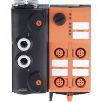
AC5227 - Soundcard IFM - Free user manual and instructions
Find the device manual for free AC5227 IFM in PDF.



| Product type | Pneumatic interface module AS-i (AirBox) |
| Model | AC5227 |
| Brand | IFM |
| Number of inputs | 2 inputs (sensors) |
| Number of pneumatic outputs | 2 outputs (3/2 valves) |
| Power supply | Via AS-i flat cable (30 V DC) |
| Operating pressure | 2...8 bar |
| Pneumatic connection | Rilsan tubes, outer diameter according to CETOP RP 54 P |
| AS-interface version | 3.0 (downward compatible) |
| AS-i profile | S-3.F.F |
| Addressing mode | Standard (non-extended) |
| LED indicators | PWR (green), FAULT (red), AUX (green), input (yellow) |
| Protection degree | IP67 (IP65 with silencer) |
| Electromagnetic compatibility | Contact discharge ±4 kV, air discharge ±8 kV |
| Required compressed air quality | Class 6-3-1 (non-lubricated) or 6-3-4 (lubricated) according to ISO 8573-1 |
| Manual control functions | Push/release or push/turn/lock |
| Maintenance | No repair possible; contact manufacturer in case of defect |
| Cleaning | Avoid dirt and dust deposits on the base and top part |
| Safety | Do not open or operate elements without function; risk of destruction |
| Spare parts | Not repairable; parts available on order (seals, plugs) |
| General information | Use in industrial environment; follow pneumatic safety regulations |
Frequently Asked Questions - AC5227 IFM
User questions about AC5227 IFM
0 question about this device. Answer the ones you know or ask your own.
Ask a new question about this device
Download the instructions for your Soundcard in PDF format for free! Find your manual AC5227 - IFM and take your electronic device back in hand. On this page are published all the documents necessary for the use of your device. AC5227 by IFM.
USER MANUAL AC5227 IFM
Pneumatik
Functions and features
• maximum number of modules per master: 31 (AC5227) and 62 (AC5228 / AC5243)
- AS-interface version 3.0, downward compatible
- connection to the pneumatic system via tube fitting, outside calibration according to CETOP standards RP 54 P
- operating pressure range 2...8 bar
Operation outside the indicated operating pressure range or use of incorrectly processed compressd air can cause permanent leaks and irreparable damage to the pneumatic components and may lead to malfunctioning.
Operating and display elements
![addressing interface LED labels 4 M12 sockets Locking/unlocking exhaust air [3,5] manual override operating connection [2] operating connection [4] manual override compressed air [1]](/content/2026/03/580436/images/584642e6b7678c6f2638526dc07cf5f541790ca55e9ac6633326071ec5bad473.jpg)
Parts without function. Do not open, do not actuate.
Risk of destruction.
Installation
Notes on installation from page 26.
Addressing
At the factory the address is set to 0.
Addressing with the AC1144 addressing unit
When mounted and wired the module can be addressed with the addressing cable (E70213) via the implemented addressing interface.
If a slave with the extended addressing mode is used in combination with a master of the first generation (version 2.0), the parameter P3 must be 1 and the output bit D3 must be 0*. The output bit D3 and the parameter bit P3 must not be used. * Default setting
If a slave with the extended addressing mode is used in combination with a master of the first generation (version 2.0), an address between 1A and 31A must be assigned to this slave.
Electrical connection
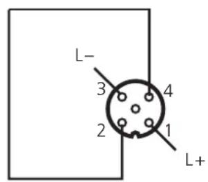
Connect the plugs of the sensors to the M12 sockets.
Cover the unused sockets with protective caps (E73004)*, the addressing socket with the supplied protective cap. Tightening torque 0.6...0.8 Nm.
To guarantee protection rating IP 67 you also have to
- use the flat cable end seal (E70413)* if the module is at the end of the cable line
• discharge exhaust air via the tube connection
* to be ordered separately

If the AirBox is operated with silencer, the protection rating is IP65.
AC5227
2 inputs / 2 pneumatic outputs
AS-i profile S-3.F.F / extended addressing mode: no
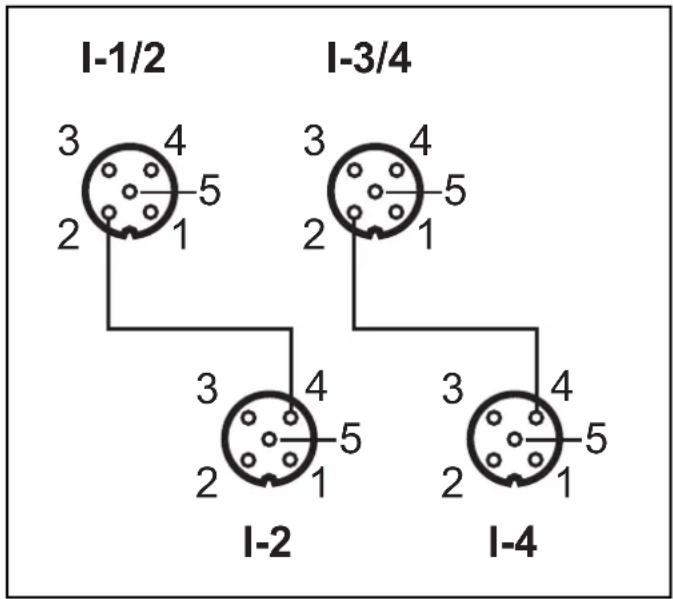
| Data bit D0 D1 D2 D3 | ||||
| Input 1234 | ||||
| Socket I-1 I-2 -- | ||||
| Pin 2+4 2+4 -- | ||||
| Pneumatic output -- 2 4 |
Inputs (standard)
AC5228
4 inputs / 2 pneumatic outputs
AS-i profile S-7.A.E / extended addressing mode: yes
| Data bit D0 D1 D2 D3 | ||||||
| Input 1 2 3 4 | ||||||
| Socket I1/2 I1/2 I2 I3/4 | 3/4 | 3/4 I4 | ||||
| Pin | 4 | 2 | 4 | 4 | 2 | 4 |
| Pneumatic output 2 4 - | - | |||||
AC5243
4 inputs / 2 pneumatic outputs
AS-i Profil S-7.A.E / extended addressing mode: yes / AUX
| Data bit D0 D1 D2 D3 | ||||||
| Input 1 2 3 4 | ||||||
| Socket I1/2 I1/2 I2 I3/4 I3/4 I4 | ||||||
| Pin 4 2 4 4 2 4 | ||||||
| Pneumatic output 2 4 - | - | |||||
Inputs (Y-circuit)
Pneumatics
Circuit diagram pneumatics 2x 3/2-way valve
![graph TD A["Component 1"] --> B["Valve 1"] B --> C["Component 2"] C --> D["T"] D --> E["Actuator 3"] E --> F["Reservoir"] G["Component 4"] --> H["Valve 4"] H --> I["T"] I --> J["Component 5"] J --> K["Reservoir"] L["Reservoir"] --> M["T"] M --> N["Actuator 5"] O["Reservoir"] --> P["T"] P --> Q["Comp…](/content/2026/03/580436/images/00989a844efbd6f34fee37049fa660e889061b9aff0194747e6282dcaf2338ac.jpg)
Compressed air
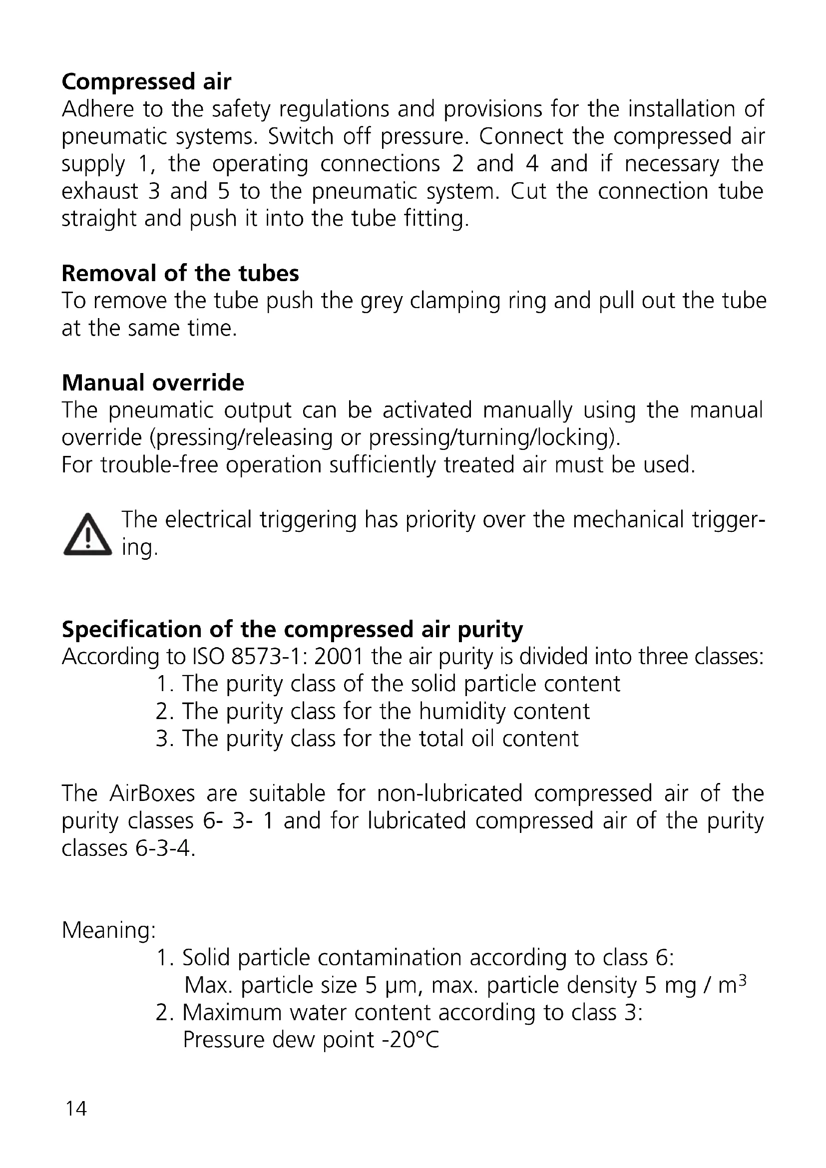
Adhere to the safety regulations and provisions for the installation of pneumatic systems. Switch off pressure. Connect the compressed air supply 1, the operating connections 2 and 4 and if necessary the exhaust 3 and 5 to the pneumatic system. Cut the connection tube straight and push it into the tube fitting.
Removal of the tubes
To remove the tube push the grey clamping ring and pull out the tube at the same time.
Manual override
The pneumatic output can be activated manually using the manual override (pressing/releasing or pressing/turning/locking).
For trouble-free operation sufficiently treated air must be used.

The electrical triggering has priority over the mechanical triggering.
Specification of the compressed air purity
According to ISO 8573-1: 2001 the air purity is divided into three classes:
- The purity class of the solid particle content
- The purity class for the humidity content
- The purity class for the total oil content
The AirBoxes are suitable for non-lubricated compressed air of the purity classes 6-3-1 and for lubricated compressed air of the purity classes 6-3-4.
Meaning:
- Solid particle contamination according to class 6:
Max. particle size 5 μm, max. particle density 5 mg / m³ -
Maximum water content according to class 3:
Pressure dew point -20°C -
Maximum total oil content according to class 1: for non-lubricated compressed air 0.01 mg / m 3 Maximum total oil content according to class 4: for lubricated compressed air < 5 mg / m 3 , this corresponds to approx. 1 oil drop / 4000 litres of air
Once the AirBox has been operated with lubricated air, it always has to be operated with lubricated air as the oil removes the initial lubrication.
Electromagnetic compatibility (EMC)
The AirBox is rated for operation in industrial environments. The test of the electrostatic discharge was carried out in accordance with EN 61000-4-2 with the following test levels:
- contact discharge ±4 kV
- air discharge ±8 kV
Special applications such as the conveying and distribution of bulk material can generate higher electrostatic charges.
To avoid electrostatic discharge the following remedial actions are possible, among others:
• Equalisation of potential according to the installation instructions
- Separate laying of
- signal and bus cables
- Physical separation of the AirBox and all cables from all parts carrying or discharging electrostatic charges.
If these discharges are not avoided there is the danger of:
- injury to/incapacitation of operators and maintenance staff
- spark formation
- damage to the AirBox
- damage to the electrical equipment
Operation
Avoid build-up of dirt and dust on the upper and lower parts so that the locking mechanism is not affected.
Check the reliable functioning of the unit. Display by LEDs:
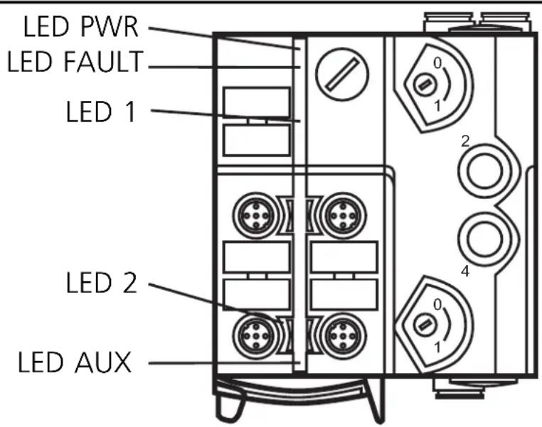
• LED 2 yellow: input switched
• LED PWR green: AS-i voltage supply ok
- LED FAULT red lights: AS-i communication error, slave does not participate in the „normal“ exchange of data, e.g. slave address 0
- LED FAULT red flashing: peripheral fault, e.g. overload or short circuit of the sensor supply
Important notes on LED AUX and LED 1
- LED AUX green: AUX voltage supply OK (AC5243) Application of the AUX voltage is only indicated if the AS-i voltage is also available.
- LED 1 yellow: Only indicates the logic state of the PLC outputs. The pneumatic output status does not necessarily correspond to the indicated status of LED 1. The pneumatic output status is not indicated on the unit.
Maintenance / repair
The unit must not be modified nor can it be repaired. In case of a fault please contact the manufacturer.
Technical data
Technical data and further information at www.ifm-electronic.com --> Select your country --> Data sheet direct
Pneumatique
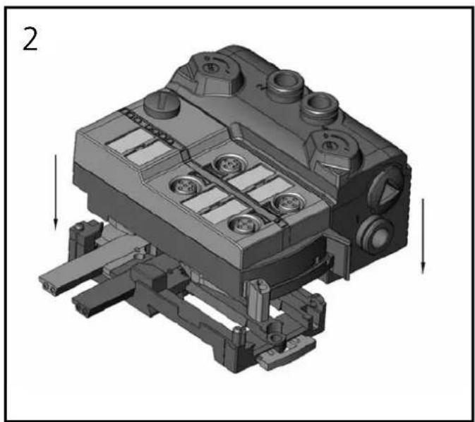
Orientation of the flat cable on delivery
Carefully place the yellow and optionally the black AS-i flat cable (AC5253) into the profile slot.
Mount the upper part.
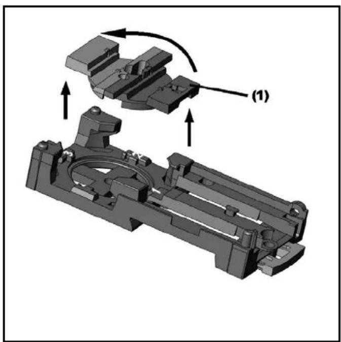
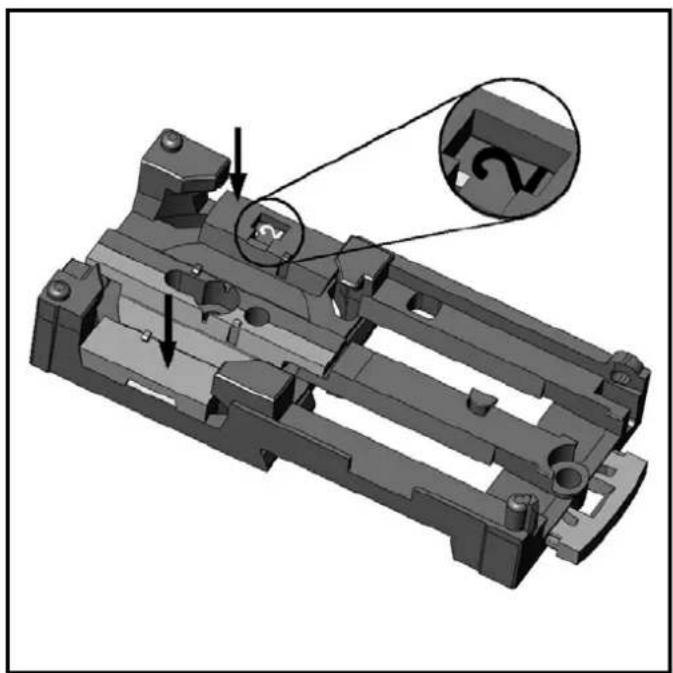
With the supplied lower part the flat cable can be aligned in three directions.
For the requested direction place the flat cable guide (1) accordingly.
Settings at the lower part
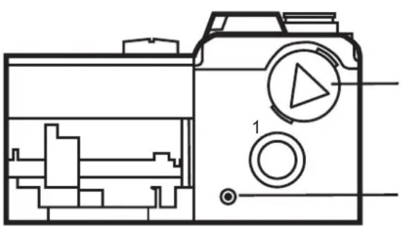
Select the position 1, 2 or 3 depending on the requested flat cable alignment ( → ).
A = Factory setting
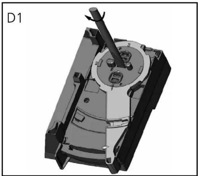
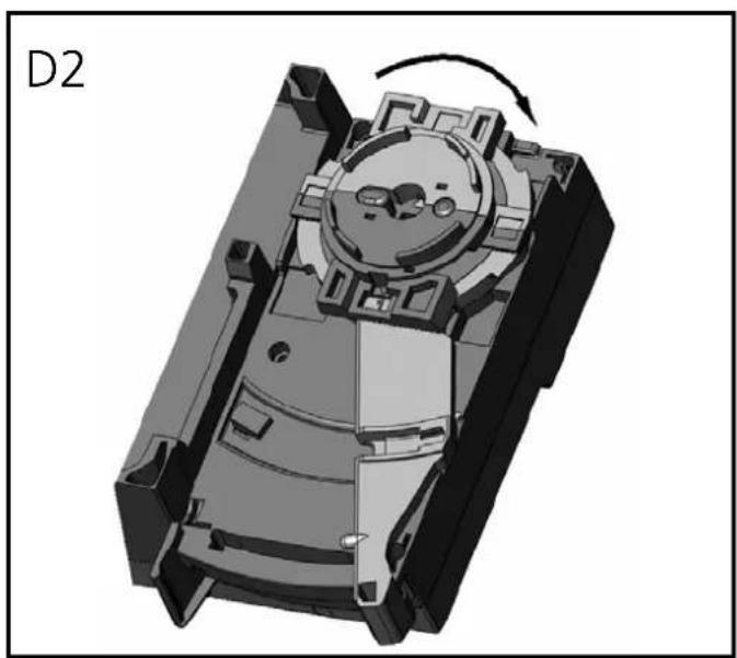
Settings at the upper part
Then set the selected position at the upper part. To do so, turn the arrow to the corresponding number (figure D1 and D2).
Use a tool, e.g. a screwdriver (figure D1) or the yellow / black flat cable guide (figure D2).
Open the unit using a tool as shown (e.g. screwdriver).
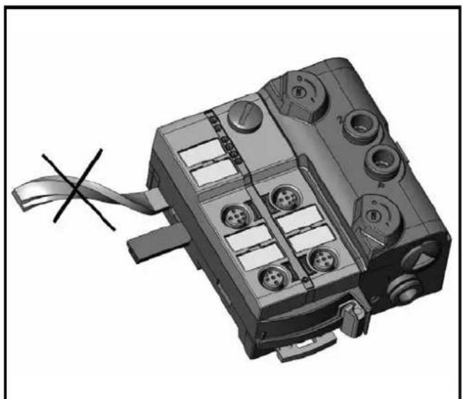
Take care in laying the AS-i flat cable, the flat cable should be laid straight for about 15 cm.
- PNEUMATIK
- FUNCTIONS AND FEATURES
- INSTALLATION
- ADDRESSING
- ADDRESSING WITH THE AC1144 ADDRESSING UNIT
- ELECTRICAL CONNECTION
- AC5227
- AC5228
- AC5243
- PNEUMATICS
- COMPRESSED AIR
- REMOVAL OF THE TUBES
- MANUAL OVERRIDE
- SPECIFICATION OF THE COMPRESSED AIR PURITY
- MEANING
- ELECTROMAGNETIC COMPATIBILITY (EMC)
- OPERATION
- IMPORTANT NOTES ON LED AUX AND LED 1
- MAINTENANCE / REPAIR
- TECHNICAL DATA
- PNEUMATIQUE
- ORIENTATION OF THE FLAT CABLE ON DELIVERY
- SETTINGS AT THE LOWER PART
- SETTINGS AT THE UPPER PART
Brand : IFM
Model : AC5227
Category : Soundcard