E33252 - Welding machine IFM - Free user manual and instructions
Find the device manual for free E33252 IFM in PDF.


User questions about E33252 IFM
0 question about this device. Answer the ones you know or ask your own.
Ask a new question about this device
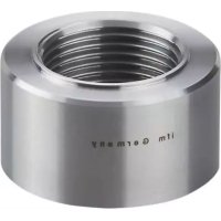
Download the instructions for your Welding machine in PDF format for free! Find your manual E33252 - IFM and take your electronic device back in hand. On this page are published all the documents necessary for the use of your device. E33252 by IFM.
USER MANUAL E33252 IFM
Installation instructions
Flushline pipe adapter
for devices with Aseptoflex Vario adaption
E3325x
Contents
1 Preliminary note.... 3
1.1 Symbols used.... 3
1.2 Warnings.... 3
2 Safety instructions 4
3 Transport, handling and storage 5
4 Intended use 6
5 Installation.... 7
5.1 Basics 7
5.2 Adapter with leakage port 8
5.3 Sensor display marking 8
5.4 Forming.... 8
5.5 Tack welding 9
5.6 Welding operation 9
5.7 After welding 10
5.8 Installing the sensor with an Aseptoflex Vario adaption 10
6 Set-up 12
7 Disposal and return 13
1 Preliminary note
You will find instructions, technical data, approvals and further information using the QR code on the unit / packaging or at documentation.ifm.com.
1.1 Symbols used
√ Requirement
Instruction
Reaction, result
bold Designation of keys, buttons or indications
→ Cross-reference without link
→ Cross-reference with link

Important note
Non-compliance may result in malfunction or interference

Information
Supplementary note
1.2 Warnings
Warnings indicate the possibility of personal injury and damage to property. This enables safe product handling. Warnings are graded as follows:

WARNING
Warning of serious personal injury
▷ If the warning is not observed, fatal and serious injuries are possible.

CAUTION
Warning of minor to moderate personal injury
▷ If the warning is not observed, minor to moderate injuries are possible.

ATTENTION
Warning of damage to property
▷ If the warning is not observed, damage to property is possible.
2 Safety instructions
- The product described is a subcomponent for integration into a system.
- The system architect is responsible for the safety of the system.
-
The system architect undertakes to perform a risk assessment and to create documentation in accordance with legal and normative requirements to be provided to the operator and user of the system. This documentation must contain all necessary information and safety instructions for the operator, the user and, if applicable, for any service personnel authorised by the architect of the system.
-
Read this document before setting up the product and keep it during the entire service life.
- The product must be suitable for the corresponding applications and environmental conditions without any restrictions.
- Only use the product for its intended purpose (→ Intended use).
- Only use the product for permissible media (→ Technical data).
- If the operating instructions or the technical data are not adhered to, personal injury and/or damage to property may occur.
- The manufacturer assumes no liability or warranty for any consequences caused by tampering with the product or incorrect use by the operator.
- Installation, set-up, operation and maintenance of the product must be carried out by qualified personnel authorised by the machine operator.
- The welding operation must be carried out by authorised personnel.
- The welding operation must be carried out carefully and according to state-of-the-art technology.
- During the welding process, ensure sufficient fume extraction.
- Protect the product against damage.

CAUTION
During the welding operation, the adapter, the surrounding material and any welding aid used can increase in temperature to over 65\ °C ( 149\ °F ).
▷ Risk of burns.
▶ Allow all components to cool down.
3 Transport, handling and storage
▶ Store the product in its original packaging.
▶ Observe the permissible ambient conditions for the product during storage (→ Technical data).
▶ In case of return shipment, ensure that the product or components are cleaned especially from dangerous and toxic substances.
4 Intended use
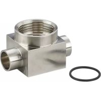
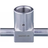
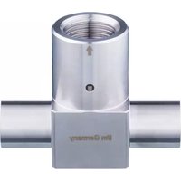
The welding adapter (hereinafter referred to as inline adapter) allows installation of sensors with Aseptoflex Vario adaption in pipe systems. Using this ensures a hygienic integration of the sensor. At the same time the required welding operation is reduced to orbital welding at the two pipe ends.

The sensor to be mounted is flush with the inner wall of the pipe, which makes it fit for drainage. Vertical installation of the sensor into a horizontal pipe is possible. The medium flows directly across the sensor surface, which guarantees ideal cleaning conditions in accordance with standardised CIP conditions.

Installation of a pressure sensor: the small recess of the ceramic measuring cell inside the sensor must be taken into consideration if the sensor is installed from below into a horizontal pipe.

Installation of sensors with probe: in order to prevent malfunction or damage, the probe must be shorter than the internal pipe diameter.
Note: the available pipe cross-section is restricted by the probe of the installed sensor. Observe minimum distances from probe tip to opposite walls ➕ Operating instructions of the installed device.

Pressure Equipment Directive (PED): the inline adapter complies with the Pressure Equipment Directive and is designed and manufactured for group 2 fluids in accordance with the sound engineering practice.
5 Installation

Observe and adhere to state-of-the-art technology and applicable regulations during the welding process.

Carefully read and apply the operating instructions of all components used.

ATTENTION
Danger to the plant and the environment during welding operations and rework.
▶ Consider potential dangers and adhere to applicable regulations and guidelines.

CAUTION
During the welding operation, the adapter, the surrounding material and any welding aid used can increase in temperature to over 65\ °C ( 149\ °F ).
▷ Risk of burns.
▶ Allow all components to cool down.

WARNING
Dangers to persons during welding operations, rework and pressure tests.
▶ Consider potential dangers and adhere to applicable regulations and guidelines.
5.1 Basics
The inline adapter can be welded into pipes or provided with connection fittings.

During the installation or the welding process, the experience of qualified staff has priority. Procedures deviating from these instructions are permissible. (DIN EN ISO 3834-1 to -6 and DIN FB CEN ISO / TR3834-6).

The pipe must correspond with the wall thickness and the diameter of the two pipe connections on the inline adapter (DIN 11866).

The inline adapter must not warp.

Adapter with leakage ports:
For reliable draining: Align the adapter with only one leakage port so that the leakage port is located at the lowest possible point. Adapter with leakage port ➞ 8

Recommendation: Application of the TIG method in accordance with ➕ EHEDG DOC 35 “Hygienic welding of stainless steel tubing in the food processing industry”.

Recommendation: Use the welding mandrel E30452 for optimum heat dissipation.
▶ Ensure correct alignment of the inline adapter.
▶ Prepare the pipe ends for orbital welding.
▶ Ensure rectangularity, freedom from burrs and chamfers.
▶ The inline adapter and its surfaces must be free from any kind of soiling and damage.
▶ Choose welding materials that are appropriate for the material of the adapter and the pipe.
▶ First, weld one side of the inline adapter to a pipe, then weld the other side to the other pipe.
5.2 Adapter with leakage port

Für eine sichere Selbstentleerung bei einem Adapter mit mehreren Leckagebohrungen:
▶ Eine der Leckagebohrungen so ausrichten, dass sich diese am tiefsten Punkt befindet.

Für eine sichere Selbstentleerung bei einem Adapter mit einer Leckagebohrung:
▶ Align the leakage port so that it is located at the lowest possible point.
5.3 Sensor display marking

The marking (1) indicates the direction of the sensor display (once fitted), provided the sensor is equipped with a display.

Fig. 1: Aseptoflex Vario inline adapter
1: Marking
5.4 Forming

Welding with stainless steel: the welding material may not come into contact with oxygen during the welding process.
▶ Rinse the inside of the pipe with forming gas.
▶ Seal the pipe upstream and downstream of the weld seam using an end cap.
▶ Connect feed line for inert gas to the pipe.
▶ Bore holes into the opposite side (pipe seal), so that the gas can escape.
▶ Ensure emission of gas with the required volume flow.

The forming gas may not produce any pressure inside the pipe.

The forming gas must be suitable for the applied welding method: TIG; MIG; MAG.
5.5 Tack welding
▶ Ensure plane-parallel alignment of the pipe end, perpendicular to the axis.
▶ Clamp the inline adapter and the pipe against each other using an appropriate mounting solution.
▶ During welding and the following cooling phase the sensor must not be in place.

Using forming gas is recommended during the tack welding process.
▶ Add weld tacks between the inline adapter and the pipe ends. Apply each new tack on the opposite side of the former, inside and outside of the pipe.
▷ Apply tack welds at regular intervals around the pipe.


Recommendation: apply at least 8 tacks in order to prevent damage and torsion of the inline adapter during the welding process.
5.6 Welding operation

The power of the welding device must be adapted to the thickness of the wall.
In case of hygienic requirements take the appropriate measures to obtain a hygienic weld seam, in particular:
Choose the suitable welding method.
Choose the suitable welding parameters.
Align pipe ends accurately to avoid gaps or linear misalignment, etc.
Avoid overheating between the weld seams.
Avoid undercuts (hygienic areas) ➕ EHEDG DOC 35.
▶ During welding and the following cooling phase the sensor must not be in place.
▶ Apply weld seams between the weld tacks. Add each new seam on the opposite side of the former.

Recommendation: start welding at the lowest point (A).

▶ The sealing edge of the adapter (1) must not be damaged by weld spatter or similar.

Fig. 2: Aseptoflex Vario inline adapter
1: Sealing edge
5.7 After welding
▶ Let the adapter cool down.
▶ If used: remove the welding mandrel.
▶ Check the quality of the weld seam. It must meet the applicable requirements for a hygienic weld seam, in particular:
• full weld penetration
• no gaps / cracks / porosity / tarnish
• no increased surface roughness
• no protruding outwards
- no sagging inwards
- no inclusions
▶ The thread and sealing edge must be free from welding residues.

If the sealing edge of the inline adapter is damaged, the adapter can no longer be used.
▶ Replace the inline adapter.
5.8 Installing the sensor with an Aseptoflex Vario adaption

General information for sensor installation: ➞ Operating instructions of the sensor.

A lubricating paste is required to install the sensor. It must be suitable and approved for the given application and compatible with the elastomers used (e.g. seal).

The inline adapter is supplied with an EPDM O-ring = order no. E30054. More sealing rings are available as accessories: FKM O-ring = order no. E30123.
▶ Remove the protective packaging only just before mounting.
▶ Ensure cleanliness of the sealing areas.

▶ Screw the sensor into the adapter.
▶ Tighten the sensor using a spanner until you can feel the end stop (this corresponds to a maximum tightening torque of approx. 35Nm).

Too much torque may impair the seal.

If the sealing area is damaged:
▶ Replace the adapter.
▶ Place the sealing ring (B) in the groove (C) of the sensor.
▶ Use the lubricating paste (A) sparingly and apply it to threaded parts.
6 Set-up
▶ Before setting up the system: Check all components for ingress resistance.
Setting up the sensor: ➕ Operating instructions of the sensor.
7 Disposal and return
▶ After use, dispose of the unit in an environmentally friendly way in accordance with the applicable national regulations.
▶ In case of return shipment, ensure that the unit is free from soiling, especially from dangerous and toxic substances.

- 1 PRELIMINARY NOTE
- 1.1 SYMBOLS USED
- 1.2 WARNINGS
- 2 SAFETY INSTRUCTIONS
- 3 TRANSPORT, HANDLING AND STORAGE
- 4 INTENDED USE
- 5 INSTALLATION
- 5.1 BASICS
- 5.2 ADAPTER WITH LEAKAGE PORT
- 5.3 SENSOR DISPLAY MARKING
- 5.4 FORMING
- 5.5 TACK WELDING
- 5.6 WELDING OPERATION
- 5.7 AFTER WELDING
- 5.8 INSTALLING THE SENSOR WITH AN ASEPTOFLEX VARIO ADAPTION
- 6 SET-UP
- 7 DISPOSAL AND RETURN
Brand : IFM
Model : E33252
Category : Welding machine