JMW3430LM - Oven JENN-AIR - Free user manual and instructions
Find the device manual for free JMW3430LM JENN-AIR in PDF.
| Product Type | Combination microwave and convection oven |
| Brand | JENN-AIR |
| Model | JMW3430LM |
| Power Supply | 240 V / 120 V, 20 A |
| Cooking Functions | Microwave, convection, grill, traditional baking, slow roasting, keep warm, dough proofing, self-cleaning |
| Control Type | Touch screen with user interface |
| Diagnostic Mode | Accessible via key sequence (Lower Oven > Lower Light > Oven Cancel repeated 3 times) |
| Sensors | Cavity temperature, meat probe, humidity, magnetron thermistor |
| Heating Elements | Bake element, broil element, upper and lower convection elements |
| Fans | Convection fan (2 speeds), cooling fan (2 speeds) |
| Safety | Multiple door switches, motorized latch, safety thermostats, fuses |
| Lighting | Halogen lamp in microwave cavity, oven lamp |
| Connectivity | Built-in Wi-Fi (antenna) |
| Maintenance | Self-cleaning cycle, manual surface cleaning |
| Spare Parts | Available through authorized technical service (appliance manager, inverter, magnetron, etc.) |
| Repairability | Dedicated technical manual for technicians, replaceable components |
| Compatibility | Use of microwave-safe and conventional oven-safe dishes |
| General Information | User manual available in multiple languages, including French |
Frequently Asked Questions - JMW3430LM JENN-AIR
User questions about JMW3430LM JENN-AIR
0 question about this device. Answer the ones you know or ask your own.
Ask a new question about this device
Download the instructions for your Oven in PDF format for free! Find your manual JMW3430LM - JENN-AIR and take your electronic device back in hand. On this page are published all the documents necessary for the use of your device. JMW3430LM by JENN-AIR.
USER MANUAL JMW3430LM JENN-AIR
Electrical Shock Hazard
Only authorized technicians should perform diagnostic voltage measurements.
After performing voltage measurements, disconnect power before servicing.
Failure to follow these instructions can result in death or electrical shock.
WARNING

Electrical Shock Hazard
Disconnect power before servicing.
Replace all parts and panels before operating.
Failure to do so can result in death or electrical shock.
Voltage Measurement Safety Information
When performing live voltage measurements, you must do the following:
■ Verify the controls are in the off position so that the appliance does not start when energized.
- Allow enough space to perform the voltage measurements without obstructions.
- Keep other people a safe distance away from the appliance to prevent potential injury.
■ Always use the proper testing equipment.
■ After voltage measurements, always disconnect power before servicing.
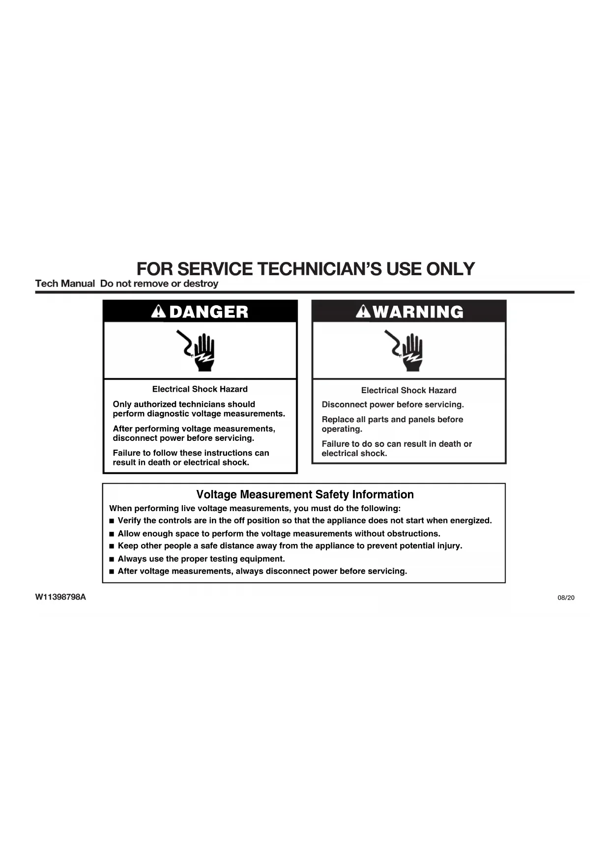
FOR SERVICE TECHNICIAN'S USE ONLY
IMPORTANT: Electrostatic Discharge (ESD) Sensitive Electronics
ESD problems are present everywhere. ESD may damage or weaken the electronic control assembly. The new control assembly may appear to work well after repair is finished, but failure may occur at a later date due to ESD stress.
■ Use an antistatic wrist strap. Connect wrist strap to green ground connection point or unpainted metal in the appliance
-OR-
Touch your finger repeatedly to a green ground connection point or unpainted metal in the appliance.
■ Before removing the part from its package, touch the antistatic bag to a green ground connection point or unpainted metal in the appliance.
■ Avoid touching electronic parts or terminal contacts; handle electronic control assembly by edges only.
■ When repackaging failed electronic control assembly in antistatic bag, observe above instructions.
PRECAUTIONS TO BE OBSERVED BEFORE AND DURING SERVICING TO AVOID POSSIBLE EXPOSURE TO EXCESSIVE MICROWAVE ENERGY
a. Do not operate or allow the oven to be operated with the door open.
b. Make the following safety checks on all ovens to be serviced before activating the magnetron or other microwave source, and make repairs as necessary:
- Interlock Operation
- Proper Door Closing
- Seal and Sealing Surfaces (Arcing, Wear and Other Damage)
- Damage to or Loosening of Hinges and Latches
- Evidence of Dropping or Abuse
c. Before turning on microwave power for any service test or inspection within the microwave generating compartments, check the magnetron, waveguide or transmission line, and cavity for proper alignment, integrity and connections.
d. Any defective or misadjusted components in the interlock, monitor, door seal, and microwave generation and transmission systems shall be repaired, replaced, or adjusted by procedures described in service manual before the oven is released to the owner.
e. A microwave leakage check to verify compliance with the CSA should be performed on each oven prior to release to the owner.
f. Do not attempt to operate the oven if the door glass is broken.
FOR SERVICE TECHNICIAN'S USE ONLY
Diagnostics
IMPORTANT: Before powering MWO magnetron, be sure that a load, such as a microwave-safe cup of water, is present in the microwave oven cavity.
Unplug oven or disconnect power before performing the following checks:
■ A potential cause of a control not functioning is corrosion on connections. Observe connections and check for continuity with an ohmmeter.
All tests/checks should be made with a VOM or DVM having a sensitivity of 20,000 Ω per volt DC or greater.
- Check all connections before replacing components, looking for broken or loose wires, failed terminals, or wires not pressed into connectors far enough. Damaged harness must be entirely replaced. Do not rework a harness.
■Resistance checks must be made with power cord unplugged from outlet, and with wiring harness or connectors disconnected.
IMPORTANT: Do not replace the control if there is no evidence of any failure.
To Enter Diagnostics Mode:
Before proceeding with any corrective action, perform the following steps to enter the Diagnostics mode.
-
Enter Diagnostics mode by pressing LOWER OVEN>LOWER LIGHT>OVEN CANCEL (repeat two more times)
TIP: You can also swipe your finger from left to right over the buttons 3 times.
NOTE: You do not need to wait for any audible or visual feedback from the control between keypad presses. -
If control does not enter Diagnostics, continue repeating the keypad sequence from Step 1. All the keypads will light up when the control enters Diagnostics.
- From the Diagnostic menu, scroll to the desired selection using the touch screen.
Error Diagnostics: View and clear the failure history.
Component Activation: Manually activate each relay.
Sensors & Switches: View the traditional oven cavity temperatures and door/latch switch status.
System Information: View the model number, serial number, and software versions.
Wi-Fi: View Wi-Fi related content such as IP Address, Gateway, SSID, and connection status.
Exit Diagnostics
General Procedure: Error Codes
NOTE: All failures are stored in the failure history. To check if the error code is still present, start a cooking function and wait 1 minute to check if the error appears.
- Plug in oven or connect power.
- Enter Diagnostics mode.
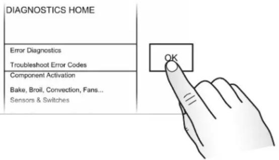
- Touch or scroll to "Error Diagnostics" in the Diagnostics menu, and then touch "OK."
text_image
DIAGNOSTICS HOME Error Diagnostics Troubleshoot Error Codes Component Activation Bake, Broil, Convection, Fans... Sensors & Switches OK- To clear error codes, touch "Clear History."
- If no failures are listed, the message "No Error" will appear on the screen.
General Procedure: Component Activation
- Plug in oven or connect power.
-
Enter Diagnostics mode.
-
Touch or scroll to "Component Activation" in the Diagnostics menu, and then touch "OK."
- Touching the following selections will activate/ deactivate corresponding relay.
| Selection Relay | |
| MW Light MW Light Relay | |
| MW Turntable MW Turntable Relay | |
| MW Cooling Fan MW Cooling Fan Relay | |
| MW Grill MW Broil Element Relay | |
| MW Convection Element MW Convection Element Relay | |
| MW Convection Fan MW Convection fan Relay | |
| MW Magnetron/Cooling Fan | MW Magnetron and MW Cooling Fan Relay |
| Oven Bake Element Oven Bake Element Relay | |
| Oven Broil Element Oven Broil Element Relay | |
| Convection Element - Up Upper Convection Element Relay | |
| Convection Element - Low Lower Convection Element Relay | |
| Convection Fan HS - Up Upper High Speed Convection Fan Relay | |
| Convection Fan LS - Up Upper Low Speed Convection Fan Relay | |
| Convection Fan HS - Low | Lower High Speed Convection Fan Relay |
| Convection Fan LS - Low | Lower Low Speed Convection Fan Relay |
| Oven Cooling Fan High Speed | Oven Cooling Fan High Speed Relay |
| Oven Cooling Fan Low Speed | Oven Cooling Fan Low Speed Triac |
| Oven Light | Oven Light Triac |
| Oven Door Latch Motor | Oven Door Latch Motor Relay |
General Procedure: Sensors & Switches
NOTE: This procedure is to view the current status of oven switches and sensor readings.
| Display | Status |
| MW Door Switch | Open or Closed |
| MW Cavity Temperature | Degrees in Celsius |
| Oven Door Switch | Open or Closed |
| Oven Latch Switch | Open or Closed |
| Oven Cavity Temperature | Degrees in Celsius |
| Oven Meat Probe Temperature | Degrees in Celsius |
- Plug in oven or connect power.
- Enter Diagnostics mode.
- Touch or scroll to "Sensors & Switches" in the Diagnostics menu, and then touch "OK."
- Touch or scroll through the Sensors & Switches menu to view the desired status.
NOTE: Touching "Back" will return the display to the main Diagnostics menu.
FOR SERVICE TECHNICIAN'S USE ONLY
General Procedure: System Information
NOTE: This procedure is to view the following system information:
| System Information Display | |
| Model # Model Information | |
| Serial # Product Serial Number | |
| UI Serial # User Interface Serial Number | |
| Oven ACU Serial # Appliance Control Unit Serial Number | |
| UI Version User Interface Software Version | |
| HMI Central SW HMI Central Board Software Version | |
| HMI Left SW HMI Left Keyboard Software Version | |
| HMI Left EE HMI Left Keyboard EEPROM Version | |
| HMI Right SW HMI Right Keyboard Software Version | |
| HMI Right EE HMI Right Keyboard EEPROM Version | |
| Kernel Version HMI Central Board Software Version | |
| Touch Calibration Version | LCD/TP FPC Tail Software Version |
| Database Version HMI Central Board Database Structure | |
| Audio Version | HMI Central Board Software Version |
| Oven ACU SW | Oven Appliance Control Unit Software Version |
| MWO ACU SW | Microwave Oven Appliance Control Unit Software Version |
| Diagnostics Entries | Number of times Diagnostic menu has been entered |
- Plug in oven or connect power.
- Enter Diagnostics mode.
-
Touch or scroll to "System Information" in the Diagnostics menu, and then touch "OK."
-
Touch or scroll through the System Information menu to view the desired status.
NOTE: Touching "Back" will return the display to the main Diagnostics menu.
General Procedure: Model Selection
NOTE: When a new User Interface is installed, you will be prompted to select a new model number upon power up. To change the model number on an existing UI, follow the steps below.
- Plug in oven or connect power.
- Enter Diagnostics mode.
- Touch or scroll to "System Information" in the Diagnostics menu, and then touch "OK."
- Touch or scroll to "Model Number," and then touch "OK."
- Touch or scroll to the correct model number in the list, and then touch "Select."
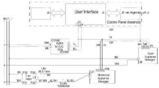
Failure/Error Display Codes
No Display - control is blank Switch Mode Power Supply (SMPS), User Interface (UI)
SUGGESTED CORRECTIVE ACTION PROCEDURE
NOTE: Before starting any test, cycle power to the oven (power Off, wait 10 seconds, and then power On).
- Unplug oven or disconnect power.
- Remove plastic cover from UI. Check connection from display to UI.
- Check wiring from main line to SMPS (CONN 7).
flowchart
graph TD
    A["User Interface"] --> B["Control Panel Assembly"]
    B --> C["User Appliance Manager"]
    C --> D["Memory Appliance Manager"]
    D --> E["Control Panel Assembly"]
    E --> F["User Interface"]
    F --> G["Control Panel Assembly"]
    G --> H["User Appliance Manager"]
    H --> I["Control Panel Assembly"]
    I --> J["User Interface"]
    J --> K["Control Panel Assembly"]
    K --> L["User Appliance Manager"]
    L --> M["Control Panel Assembly"]
    M --> N["User Appliance Manager"]
    N --> O["Control Panel Assembly"]
    O --> P["User Appliance Manager"]
    P --> Q["Control Panel Assembly"]
    Q --> R["User Appliance Manager"]
    R --> S["Control Panel Assembly"]
    S --> T["User Appliance Manager"]
    T --> U["Control Panel Assembly"]
    U --> V["User Appliance Manager"]
    V --> W["Control Panel Assembly"]
    W --> X["User Appliance Manager"]
    X --> Y["Control Panel Assembly"]
    Y --> Z["User Appliance Manager"]
    Z --> AA["Control Panel Assembly"]
    AA --> AB["User Appliance Manager"]
    AB --> AC["Control Panel Assembly"]
    AC --> AD["User Appliance Manager"]
    AD --> AE["Control Panel Assembly"]
    AE --> AF["User Appliance Manager"]
    AF --> AG["Control Panel Assembly"]
    AG --> AH["User Appliance Manager"]
    AH --> AI["Control Panel Assembly"]
    AI --> AJ["User Appliance Manager"]
    AJ --> AK["Control Panel Assembly"]
    AK --> AL["User Appliance Manager"]
    AL --> AM["Control Panel Assembly"]
    AM --> AN["User Appliance Manager"]
    AN --> AO["Control Panel Assembly"]
    AO --> AP["User Appliance Manager"]
    AP --> AQ["Control Panel Assembly"]
    AQ --> AR["User Appliance Manager"]
    AR --> AS["Control Panel Assembly"]
    AS --> AT["User Appliance Manager"]
    AT --> AU["Control Panel Assembly"]
    AU --> AV["User Appliance Manager"]
    AV --> AW["Control Panel Assembly"]
    AW --> AX["User Appliance Manager"]
    AX --> AY["Control Panel Assembly"]
    AY --> AZ["User Appliance Manager"]
    AZ --> BA["Control Panel Assembly"]
    BA --> BB["User Appliance Manager"]
    BB --> BC["Control Panel Assembly"]
    BC --> BD["User Appliance Manager"]
    BD --> BE["Control Panel Assembly"]
    BE --> BF["User Appliance Manager"]
    BF --> BG["Control Panel Assembly"]
    BG --> BH["User Appliance Manager"]
    BH --> BI["Control Panel Assembly"]
    BI --> BJ["User Appliance Manager"]
    BJ --> BK["Control Panel Assembly"]
    BK --> BL["User Appliance Manager"]
    BL --> BM["Control Panel Assembly"]
    BM --> BN["User Appliance Manager"]
    BN --> BO["Control Panel Assembly"]
    BO --> BP["User Appliance Manager"]
    BP --> BQ["Control Panel Assembly"]
    BQ --> BR["User Appliance Manager"]
    BR --> BS["Control Panel Assembly"]
    BS --> BT["User Appliance Manager"]
    BT --> BU["Control Panel Assembly"]
- Check connection from wiring harness to UI (J15).
- Check proper voltage input at J15-2 (GND) to J15-4 (14 VDC) on the UI by completing the following steps:
- Connect voltage measurement equipment to J15-2 and J15-4 on UI.
- Plug in oven or reconnect power.
- Measure voltage and confirm voltage reading is 14 VDC. If voltage is correct, unplug oven or disconnect power and go to Step 13. If voltage is not correct, go to Step 9.
- Unplug oven or disconnect power. Replace the SMPS.
- Reassemble all parts and panels before operating.
-
Plug in oven or reconnect power.
-
Check for control board display. If still no display, unplug oven or disconnect power.
- Replace HMI-Central/UI board.
- Reassemble all parts and panels before operating.
- Plug in oven or reconnect power. If the UI was replaced, follow the on-screen prompts to select the model number.
- Verify operation is normal. If problem persists, replace the Control Panel Assembly and repeat steps 14 through 16.
FOR SERVICE TECHNICIAN'S USE ONLY
User Interface not reacting to touch
Control Panel Assembly
SUGGESTED CORRECTIVE ACTION PROCEDURE
NOTE: Before starting any test, cycle power to the oven (power Off, wait 10 seconds, and power On).
- Enter the Diagnostic menu, and then touch POWER.
-
To reset Touch Calibration: unplug oven or disconnect power, wait 10 seconds, and then plug in oven or reconnect power. If still no response, go to Step 3.
-
Unplug oven or disconnect power.
-
Replace Control Panel Assembly.
-
Reassemble all parts and panels before operating.
-
Plug in oven or reconnect power.
-
Verify operation is normal.
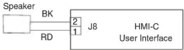
No Sound Speaker, Control Panel Assembly
SUGGESTED CORRECTIVE ACTION PROCEDURE
NOTE: Before starting any test, cycle power to the oven (power Off, wait 10 seconds, and power On).
-
Verify sound is enabled. Touch the Tools menu, and then scroll to the Sound menu. Confirm Key Press, Timer & Alert, and Power On & Off actions are all turned on and set to the desired volume.
-
Unplug oven or disconnect power.
-
Confirm the speaker is firmly connected to the HMI-Central/UI board at J8. If speaker is firmly connected, go to Step 4. If speaker connection is loose, reconnect and proceed to Step 5.
- Replace speaker.
- Reassemble all parts and panels before operating.
- Plug in oven or reconnect power.
- Confirm operation of the speaker. If problem persists, unplug oven or disconnect power, replace Control Panel Assembly, and repeat steps 5 through 7.
FAILURE ERROR LIKELY FAILURE CONDITION
F1 Internal E0 Oven user interface (UI) failure
SUGGESTED CORRECTIVE ACTION PROCEDURE
NOTE: Before starting any test, cycle power to the oven (power Off, wait 10 seconds, and power On).
PROCEDURE: Before proceeding, verify the error code by entering the Diagnostics menu and selecting "Error Diagnostics."
NOTE: If other error codes are stored, troubleshoot those other error codes first.
- Unplug oven or disconnect power.
- Confirm the control panel assembly is grounded to the oven chassis. If it is, go to Step 6. If it is not, fix the connection.
- Reassemble all parts and panels before operating.
- Plug in oven or reconnect power and cycle power.
- If error persists, unplug oven or disconnect power.
- Replace HMI-Central/UI board.
- Reassemble all parts and panels before operating.
- Plug in oven or reconnect power and cycle power.
-
If error persists after HMI-Central/UI board is replaced, unplug oven or disconnect power and replace Control Panel Assembly.
-
Reassemble all parts and panels before operating.
-
Plug in oven or reconnect power. Follow the on-screen prompts for model selection.
-
Verify operation is normal. Enter Diagnostics mode, select "Error Diagnostics," and clear the history. If the Control Panel Assembly was replaced, there is no need to clear the error history.
FAILURE ERROR LIKELY FAILURE CONDITION
F1 E1 Internal Oven ACU Error
SUGGESTED CORRECTIVE ACTION PROCEDURE
NOTE: Before starting any test, cycle power to the oven (power Off, wait 10 seconds, and power On).
PROCEDURE: Before proceeding, verify the error code by entering the Diagnostics mode and selecting "Error Diagnostics."
NOTE: If other error codes are stored, troubleshoot those other error codes first.
- Unplug oven or disconnect power.
- Replace the Copernicus Appliance Manager.
- Reassemble all parts and panels before operating.
- Plug in oven or reconnect power.
- If error persists after Copernicus Appliance Manager is replaced, unplug oven or disconnect power, and then go to Step 6. If not, go to Step 9.
- Replace Control Panel Assembly.
- Reassemble parts and panels before operating.
- Plug in oven or reconnect power.
- Follow the on-screen prompts to select the model number
- Verify operation is normal. Enter Diagnostics mode, select "Error Diagnostics," and clear the history. If the Control Panel Assembly was replaced, there is no need to clear the error history.
FOR SERVICE TECHNICIAN'S USE ONLY
FAILURE ERROR LIKELY FAILURE CONDITION
F1 E4 Microwave Oven Relay 4903 Error
SUGGESTED CORRECTIVE ACTION PROCEDURE
NOTE: Before starting any test, cycle power to the oven (power Off, wait 10 seconds, and then power On). After powering on, be sure that a load, such as a microwave-safe cup of water, is present in the microwave oven cavity, and start a microwave cooking function. Wait 1 minute, and then verify that the failure happens again.
- Make sure that all interlock switches works properly: when door is open, microwave light is On; when door is closed, microwave light is Off.
- Unplug oven or disconnect power.
- Check the following on the Microwave Appliance Manager:
a. Wire connections to Relay 4903.
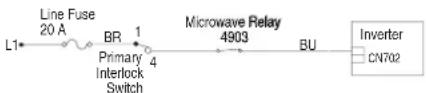
text_image
Line Fuse 20 A L1 BR 1 Primary Interlock Switch 4 Microwave Relay 4903 BU Inverter CN702b. Check if Relay 4903 is shorted. If so then go to Step 7.
- Reassemble all parts and panels before operating.
- Plug in oven or reconnect power.
- To check if the error code is still present, be sure that a load, such as a microwave-safe cup of water, is present in the microwave oven cavity, and start a cooking function in the microwave oven. Wait 1 minute to check if the error appears. If error remains, go to Step 7. If not, go to Step 10.
- Unplug oven or disconnect power and replace the Microwave Appliance Manager.
- Reassemble all parts and panels before operating.
- Plug in oven or reconnect power.
- Verify operation is normal. Enter the Diagnostics menu, select "Error Diagnostics," and clear the history.
FAILURE ERROR LIKELY FAILURE CONDITION
F1 E5 Microwave Oven Inverter Error
SUGGESTED CORRECTIVE ACTION PROCEDURE
NOTE: Before starting any test, cycle power to the oven (power Off, wait 10 seconds, and then power On). After powering on, be sure that a load, such as a microwave-safe cup of water, is present in the microwave oven cavity, and start a microwave cooking function. Wait 1 minute, and then verify that the failure happens again.
- Make sure that all interlock switches works properly: when door is open, microwave light is On; when door is closed, microwave light is Off.
- Unplug oven or disconnect power.
- Check the following on the Microwave Appliance Manager:
a. Relay 4903.
b. Connector P8.
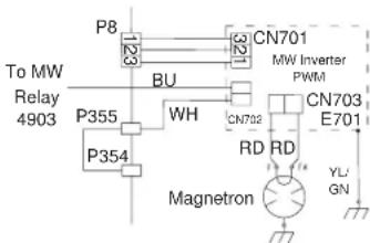
text_image
To MW Relay 4903 P8 CN701 BU P355 WH CN702 RD RD CN703 E701 Magnetron YL GN- Check the following connections on the Inverter board:
-
If the door works properly and all connections are okay, replace the Microwave Inverter Board.
-
Reassemble all parts and panels before operating.
-
Plug in oven or reconnect power.
-
To check if the error code is still present, be sure that a load, such as a microwave-safe cup of water, is present in the microwave oven cavity, and start a cooking function in the microwave oven. Wait 1 minute to check if the error appears. If error remains, then go to Step 9. If not, go to Step 17.
- Unplug oven or disconnect power.
- Replace the Magnetron.
- Reassemble all parts and panels before operating.
- Plug in oven or reconnect power.
- To check if the error code is still present, be sure that a load, such as a microwave-safe cup of water, is present in the microwave oven cavity, and start a cooking function in the microwave oven. Wait 1 minute to check if the error appears. If error remains, then go to Step 14. If not, go to Step 17.
- Unplug oven or disconnect power and replace the Microwave ACU.
- Reassemble all parts and panels before operating.
- Plug in oven or reconnect power.
- Verify operation is normal. Enter the Diagnostics menu, select "Error Diagnostics," and clear the history.
FAILURE ERROR LIKELY FAILURE CONDITION
F1 E6 Microwave Generation Error
SUGGESTED CORRECTIVE ACTION PROCEDURE
NOTE: Before starting any test, cycle power to the oven (power Off, wait 10 seconds, and then power On). After powering on, be sure that a load, such as a microwave-safe cup of water, is present in the microwave oven cavity, and start a microwave cooking function. Wait 1 minute, and then verify that the failure happens again.
- Make sure that all interlock switches works properly: when door is open, microwave light is On; when door is closed, microwave light is Off.
- Unplug oven or disconnect power.
- Check the following connections on the Microwave Appliance Manager: a. Relay 4903.
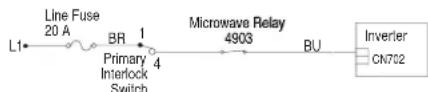
text_image
Line Fuse 20 A BR 1 Primary Interlock Switch 4 Microwave Relay 4903 BU Inverter CN702-
If the door works properly and all connections are okay, replace the Magnetron.
-
Reassemble all parts and panels before operating.
- Plug in oven or reconnect power.
- To check if the error code is still present, be sure that a load, such as a microwave-safe cup of water, is present in the microwave oven cavity, and start a cooking function in the microwave oven. Wait 1 minute to check if the error appears. If error remains, then go to Step 8. If not, go to Step 16.
- Unplug oven or disconnect power and replace the Inverter Board.
- Reassemble all parts and panels before operating.
- Plug in oven or reconnect power.
- To check if the error code is still present, be sure that a load, such as a microwave-safe cup of water, is present in the microwave oven cavity, and start a cooking function in the microwave oven. Wait 1 minute to check if the error appears. If error remains, then go to Step 12. If not, go to Step 16.
- Unplug oven or disconnect power.
- Replace the Microwave ACU.
- Reassemble all parts and panels before operating.
FOR SERVICE TECHNICIAN'S USE ONLY
- Plug in oven or reconnect power.
- Verify operation is normal. Enter the Diagnostics menu, select "Error Diagnostics," and clear the history.
FAILURE ERROR LIKELY FAILURE CONDITION
| F2 | E0 Keypad disconnected |
| Keypad | E1 Stuck/shorted key |
SUGGESTED CORRECTIVE ACTION PROCEDURE
NOTE: Before starting any test, cycle power to the oven (power Off, wait 10 seconds, and power On).
PROCEDURE: Before proceeding, verify the error code by entering the Diagnostics mode and selecting "Error Diagnostics."
- Unplug oven or disconnect power.
- Check that connectors J4, J5, J6, and J7 are firmly connected. If they are not, go to Step 3. If they are, go to Step 6.
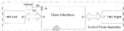
flowchart
graph LR
    A["HMI Left"] -->|J5| B["User Interface"]
    B -->|J4| C["Control Panel Assembly"]
    B -->|J3| D["Spencer"]
    D -->|BK| B
    B -->|J5| E["J7"]
    style A fill:#f9f,stroke:#333
    style B fill:#ccf,stroke:#333
    style C fill:#cfc,stroke:#333
    style D fill:#fcc,stroke:#333
    style E fill:#cff,stroke:#333
- Reconnect any loose connectors.
- Reassemble all parts and panels before operating.
- Plug in oven or reconnect power. If the failure is gone, go to Step 9. If the failure is still present, unplug oven or disconnect power.
- Replace the Control Panel Assembly.
- Reassemble all parts and panels before operating.
- Follow the on-screen prompts to select the model number
- Verify operation is normal. Enter the Diagnostics menu, select "Error Diagnostics," and clear the history. If the Control Panel Assembly was replaced, there is no need to clear the error history.
FAILURE ERROR LIKELY FAILURE CONDITION
F3
Sensors
E0 Main oven sensor open or shorted
SUGGESTED CORRECTIVE ACTION PROCEDURE
NOTE: Before starting any test, cycle power to the oven (power Off, wait 10 seconds, and power On).
PROCEDURE: Before proceeding, verify the error code by entering the Diagnostics menu and selecting "Error Diagnostics."
- Unplug oven or disconnect power.
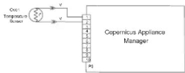
- Disconnect connector P3 from Oven Appliance Manager, and measure the resistance of the sensor between P3-1 and P3-2. Test for 1000 Ω to 1200 Ω at 77°F (25°C). Check sensor for short to ground. If checks on sensor are not correct, replace sensor and repeat the checks.
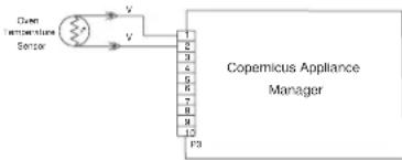
flowchart
graph TD
    A["Sensor"] -->|V| B["Copemicus Appliance Manager"]
    B -->|1| C["1"]
    B -->|2| D["2"]
    B -->|3| E["3"]
    B -->|4| F["4"]
    B -->|5| G["5"]
    B -->|6| H["6"]
    B -->|7| I["7"]
    B -->|8| J["8"]
    B -->|9| K["9"]
    B -->|10| L["10"]
    B -->|11| M["11"]
    B -->|12| N["12"]
- Reassemble all parts and panels and plug in oven or reconnect power.
- Enter Diagnostics menu and select "Sensors & Switches" to verify if the temperature shown in the Cavity Temperature display is correct (ambient temperature). If it is, go to Step 8. If it is not, unplug oven or disconnect power.
NOTE: On the status screen, the unit of measurement is Celsius.
- Replace the Copernicus Appliance Manager board.
- Reassemble all parts and panels before operating.
- Plug in oven or reconnect power.
- Verify operation is normal. Enter Diagnostics menu, select "Error Diagnostics," and clear the history.
FAILURE ERROR LIKELY FAILURE CONDITION
F3
E3 Meat Probe Connector Jack or Meat Probe Shorted
SUGGESTED CORRECTIVE ACTION PROCEDURE
NOTE: Before starting any test, cycle power to the oven (power Off, wait 10 seconds, and power On).
PROCEDURE: Before proceeding, verify the error code by entering the Diagnostics menu and selecting "Error Diagnostics."
- Unplug oven or disconnect power.
- Remove meat probe if connected.
- Disconnect connector P3 from Copernicus Appliance Manager.
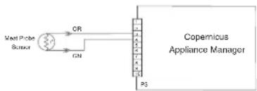
flowchart
graph LR
    A["Verat Probe Sensor"] -->|OR| B["Copemicus Appliance Manager"]
    A -->|ON| B
    B --> C["Output"]
    style A fill:#f9f,stroke:#333
    style B fill:#ccf,stroke:#333
- Check connector jack resistance between P3-3 and P3-4. If it is 0 Ω, change the jack assembly, and then go to Step 5. If it is not 0 Ω, the jack assembly is working properly. Go to Step 5.
- Plug in the meat probe and check for short to ground or open. If checks on meat probe are not correct, replace the meat probe. At 77^ F ( 25^ C) the expected value is approximately 50 k . If they are correct, replace the Copernicus Appliance Manager.
- Reassemble all parts and panels before operating.
- Plug in oven or reconnect power.
- Verify operation is normal. Enter Diagnostics menu, select "Error Diagnostics," and clear the history. Check the meat probe reading by entering Diagnostics menu and selecting "Sensors & Switches." The meat probe should detect the ambient temperature.
FOR SERVICE TECHNICIAN'S USE ONLY
FAILURE ERROR LIKELY FAILURE CONDITION
F4 E1 Microwave Cavity Temperature Sensor Error
SUGGESTED CORRECTIVE ACTION PROCEDURE
NOTE: Before starting any test, cycle power to the oven (power Off, wait 10 seconds, and then power On). After powering on, be sure that a load, such as a microwave-safe cup of water, is present in the microwave oven cavity, and start a microwave cooking function that uses the temperature sensor, such as a Convect cycle. Wait 1 minute, and then verify that the failure happens again.
- Unplug oven or disconnect power.
- Check that the P22 connection of the Microwave Appliance Manager is firmly connected. If it is, go to Step 3. If it is not, reconnect and go to Step 5.
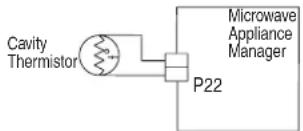
text_image
Cavity Thermistor P22 Microwave Appliance Manager- Disconnect connector P22 from the Microwave Appliance Manager, and measure the resistance of the thermistor. It should be (approximately) 230 kΩ at 77°F ± 10°F (25°C ± 10°C).
- Check thermistor for short to ground. If check on thermistor is not correct, replace the thermistor. If thermistor check is correct, replace the Microwave Appliance Manager.
- Reassemble all parts and panels before operating.
- Plug in oven or reconnect power.
- Verify operation is normal. Enter the Diagnostics menu, select "Error Diagnostics," and clear the history.
FAILURE ERROR LIKELY FAILURE CONDITION
F4 E2 Magnetron Temperature Sensor Error
SUGGESTED CORRECTIVE ACTION PROCEDURE
NOTE: Before starting any test, cycle power to the oven (power Off, wait 10 seconds, and then power On). After powering on, be sure that a load, such as a microwave-safe cup of water, is present in the microwave oven cavity, and start a microwave cooking function. Wait 1 minute, and then verify that the failure happens again.
- Unplug oven or disconnect power.
- Check that the P21 connection of the Microwave Appliance Manager is firmly connected. If it is, go to Step 3. If it is not, reconnect and go to Step 5.
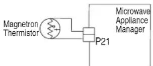
text_image
Magnetron Thermistor P21 Microwave Appliance Manager- Disconnect connector P21 from the Microwave Appliance Manager, and measure the resistance of the thermistor. It should be (approximately) 10 k at 77^ ± 10^ ( 25^ ± 10^ ).
- Check thermistor for short to ground. If check on thermistor is not correct, replace the thermistor. If thermistor check is correct, replace the Microwave Appliance Manager.
- Reassemble all parts and panels before operating.
- Plug in oven or reconnect power.
- Verify operation is normal. Enter the Diagnostics menu, select "Error Diagnostics," and clear the history.
FAILURE ERROR LIKELY FAILURE CONDITION
F4 Inputs E4 Microwave Oven Humidity Sensor Error
SUGGESTED CORRECTIVE ACTION PROCEDURE
NOTE: Before starting any test, cycle power to the oven (power Off, wait 10 seconds, and then power On). After powering on, be sure that a load, such as a microwave-safe cup of water, is present in the microwave oven cavity, and start a microwave cooking function that uses the humidity sensor, such as a Steam cycle. Wait 1 minute, and then verify that the failure happens again.
- Unplug oven or disconnect power.
- Check that the P23 connection of the Microwave Appliance Manager is firmly connected. If it is, go to Step 3. If it is not, reconnect and go to Step 5.
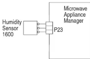
flowchart
graph LR
    A["Humidity Sensor 1600"] --> B["P23"]
    B --> C["Microwave Appliance Manager"]
- Disconnect connector P23 from Microwave Appliance Manager and measure the resistance of the sensor:
Between pins 3 and 1. It should be approximately 2800 Ω at 77°F ± 10°F (25°C ± 10°C).
Between pins 3 and 2. It should be approximately 2800 Ω at 77°F ± 10°F (25°C ± 10°C).
- Check sensor for short to ground. If checks on sensor are not correct, replace the sensor. If sensor checks are correct, replace the Microwave Appliance Manager.
- Reassemble all parts and panels before operating.
- Plug in oven or reconnect power.
- Verify operation is normal. Enter the Diagnostics menu, select "Error Diagnostics," and clear the history.
FAILURE ERROR LIKELY FAILURE CONDITION
F4 E8 Inverter Over Temperature
SUGGESTED CORRECTIVE ACTION PROCEDURE
NOTE: Before starting any test, cycle power to the oven (power Off, wait 10 seconds, and then power On). After powering on, be sure that a load, such as a microwave-safe cup of water, is present in the microwave oven cavity, and start a microwave cooking function. Wait 1 minute, and then verify that the failure happens again.
- Unplug oven or disconnect power.
- Check the following:
a. Cooling fan connection for any loose connectors.
b. Oven installation and make sure there is no air blockage at the bottom vent.
- Reassemble all parts and panels before operating.
- Plug in oven or reconnect power.
- To check if the cooling fan is stalled, be sure that a load, such as a microwave-safe cup of water, is present in the microwave oven cavity, and start a cooking function in the microwave oven. Make sure the fan is running. If it is not, unplug oven or disconnect power, replace the fan and go to Step 8. If it is, go to Step 6.
- Unplug oven or disconnect power.
- Replace the inverter board.
- Reassemble all parts and panels before operating.
- Plug in oven or reconnect power.
- Verify operation is normal. Enter the Diagnostics menu, select "Error Diagnostics," and clear the history.
FOR SERVICE TECHNICIAN'S USE ONLY
FAILURE ERROR LIKELY FAILURE CONDITION
F4 E9 Inverter and Magnetron Over Temperature
SUGGESTED CORRECTIVE ACTION PROCEDURE
NOTE: Before starting any test, cycle power to the oven (power Off, wait 10 seconds, and then power On). After powering on, be sure that a load, such as a microwave-safe cup of water, is present in the microwave oven cavity, and start a microwave cooking function. Wait 1 minute, and then verify that the failure happens again.
- Unplug oven or disconnect power.
- Check the following:
a. Cooling fan connection for any loose connectors.
b. Oven installation and make sure there is no air blockage at the bottom vent. - Reassemble all parts and panels before operating.
- Plug in oven or reconnect power.
- To check if the cooling fan is stalled, be sure that a load, such as a microwave-safe cup of water, is present in the microwave oven cavity, and start a cooking function in the microwave oven. Make sure the fan is running. If it is not, unplug oven or disconnect power, replace the fan and go to Step 8. If it is, go to Step 6.
- Unplug oven or disconnect power.
- Replace the Magnetron and the inverter board.
- Reassemble all parts and panels before operating.
- Plug in oven or reconnect power.
- Verify operation is normal. Enter the Diagnostics menu, select "Error Diagnostics," and clear the history.
FAILURE ERROR LIKELY FAILURE CONDITION
F5 Inputs E0 Door and latch switch do not agree
SUGGESTED CORRECTIVE ACTION PROCEDURE
NOTE: Before starting any test, cycle power to the oven (power Off, wait 10 seconds, and then power On).
PROCEDURE: Before proceeding, verify the error code by entering the Diagnostics menu and selecting "Error Diagnostics."
- Enter the Diagnostics menu and select "Component Activation." Touch or scroll to "Door Latch Motor," and then touch "OK." Touch "Latch Door." Wait at least 15 seconds, and then check if latch status changes on screen. If status does not change, unplug oven or disconnect power and go to Step 2. If status changes, unplug oven or disconnect power and go to Step 5.
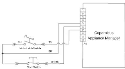
- If the oven door did not unlatch, unplug connector P3 and check for continuity (on the latch wire) between P3-5 and P3-7.
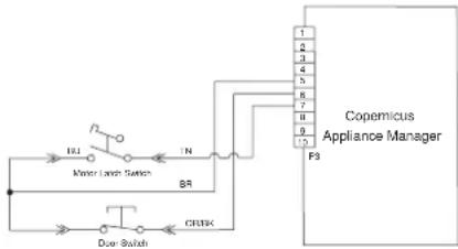
flowchart
graph TD
    A["Major Land Switch"] -->|INJ| B["Door Switch"]
    A -->|IN| C["BR"]
    A -->|N| D["CRUK"]
    D --> E["P3"]
    E --> F["Copemicus Appliance Manager"]
    style A fill:#f9f,stroke:#333
    style B fill:#ccf,stroke:#333
    style C fill:#cfc,stroke:#333
    style D fill:#fcc,stroke:#333
    style E fill:#cff,stroke:#333
    style F fill:#ffc,stroke:#333
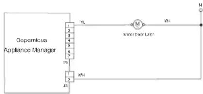
-
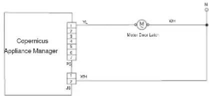
Disconnect J8 connector from Copernicus Appliance Manager.
-
Measure the resistance between connectors J8-2 and P5-1. It should be 500 Ω to 3000 Ω at 77°F (25°C).
text_image
Copernicus Appliance Manager 1 2 3 4 5 6 7 8 PS KH IR VL M Motor Door Litter KH= N- If the resistance check is outside the range, replace the affected door latch assembly. Verify that the error is gone.
- Reassemble all parts and panels.
- Plug in oven or reconnect power.
- Enter the Diagnostics menu and select "Component Activation." Check the door status on the screen by opening and closing the oven door.
- If status does not change, unplug the oven or disconnect power.
- Check for continuity with door open and closed at P3-5 to P3-6. Door open = infinite resistance. Door closed = zero resistance.
- If continuity check is not correct, replace the door latch assembly. If all checks were correct, replace Copernicus Appliance Manager.
- Reassemble all parts and panels before operating.
- Plug in oven or reconnect power.
- Verify operation is normal. Enter the Diagnostics menu, select "Error Diagnostics," and clear the history.
FAILURE ERROR LIKELY FAILURE CONDITION
F5 Inputs E'1 Latch not operating
SUGGESTED CORRECTIVE ACTION PROCEDURE
NOTE: Before starting any test, cycle power to the oven (power Off, wait 10 seconds, and then power On).
PROCEDURE: Before proceeding, verify the error code by entering the Diagnostics menu and selecting "Error Diagnostics."
- Enter the Diagnostics menu and select "Component Activation." Touch or scroll to "Door Latch Motor," and then touch "OK." Touch "Latch Door." Wait at least 15 seconds, and then check if latch status changes on screen. If status does not change, go to Step 2. If status changes, unplug oven or disconnect power, replace Copernicus Appliance Manager and go to Step 6.
- If latch status on screen is "open," unplug oven or disconnect power and check for loose harness connection between motor latch switch and P3-5 and P3-7.
flowchart
graph TD
    A["BU"] --> B["Motor Latch Switch"]
    B --> C["BR"]
    C --> D["Door Switch"]
    D --> E["O4-8K"]
    E --> F["P3"]
    F --> G["Copernicus Appliance Manager"]
    style A fill:#f9f,stroke:#333
    style B fill:#ccf,stroke:#333
    style C fill:#cfc,stroke:#333
    style D fill:#fcc,stroke:#333
    style E fill:#cff,stroke:#333
    style F fill:#ffc,stroke:#333
    style G fill:#cfc,stroke:#333
- Disconnect connector J8 from Copernicus Appliance Manager.
FOR SERVICE TECHNICIAN'S USE ONLY
- Measure the resistance between connectors J8-2 and P5-1. It should be 500 Ω to 3000 Ω at 77°F (25°C).
text_image
Copernicus Appliance Manager 1 2 3 4 5 6 7 8 9 YL M Mixer Door Lamps N YH Jb- If the resistance check is outside the range, replace the door latch assembly. Verify that the error is gone. If all checks were correct, replace Copernicus Appliance Manager.
- Reassemble all parts and panels before operating.
- Plug in oven or reconnect power.
- Verify operation is normal. Enter the Diagnostics menu, select "Error Diagnostics," and clear the history.
FAILURE ERROR LIKELY FAILURE CONDITION
| F6 | E0 Oven user interface - lost communication |
| E6 Oven appliance manager - lost communication |
SUGGESTED CORRECTIVE ACTION PROCEDURE
NOTE: Before starting any test, cycle power to the oven (power Off, wait 10 seconds, and power On).
PROCEDURE: Before proceeding, verify the error code by entering the Diagnostics mode and selecting "Error Diagnostics."
- Unplug oven or disconnect power.
- Check continuity of wirings between P1-4 and J15-3, then P1-5 and J15-2.
- Check for continuity between P1-1 and P1-2.
- If all checks are correct, replace Copernicus Appliance Manager.
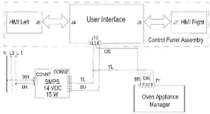
flowchart
graph TD
    A["HMI Left"] -->|J5| B["User Interface"]
    B -->|J5| C["Control Panel Assembly"]
    C -->|J7| D["HMI Right"]
    B -->|J15| E["OR"]
    B -->|J14| F["YL"]
    E --> G["CONN7"]
    F --> H["CONN2"]
    G --> I["SMPS 14 VDC 15 W"]
    H --> J["YL"]
    H --> K["BU"]
    I --> L["BR CR (17/18)"]
    J --> M["P1"]
    K --> N["P2"]
    O["Cven Appliance Manager"] --> P["CNV"]
    Q["N L2 L1"] --> R["WH"]
    Q --> S["DK"]
- Reassemble all parts and panels.
- Plug in oven or reconnect power.
- If the error appears again, unplug oven or disconnect power.
- Replace the HMI-Central/UI board.
- Reassemble all parts and panels before operating.
- Plug in oven or reconnect power.
- Follow the on-screen prompts to select the model number if the UI was replaced.
- Verify operation is normal. Enter Diagnostics menu, select "Error Diagnostics," and clear the history.
FAILURE ERROR LIKELY FAILURE CONDITION
F6 E1 Over temperature
SUGGESTED CORRECTIVE ACTION PROCEDURE
NOTE: Before starting any test, cycle power to the oven (power Off, wait 10 seconds, and then power On).
PROCEDURE: Before proceeding, verify the error code by entering the Diagnostics menu and selecting "Error Diagnostics."
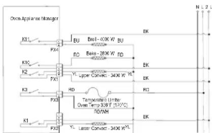
- Unplug oven or disconnect power.
- Check for elements shorted to ground. Check resistance of elements:
a. PX4-2 and PX3-2 to check Broil element (13.2 Ω to 14.6 Ω).
b. PX1-1 and PX3-2 to check Bake element (19 Ω to 21 Ω).
c. PX1-3 and PX3-2 to check Upper Conv element (15.2 Ω to 17.3 Ω).
d. PX2-4 and PX3-2 to check Lower Conv element (15.2 Ω to 17.3 Ω).
- If any element is shorted to ground, replace the element.
- Check for shorted relays.
Disconnect PX1, PX2 and PX4 connectors and check for shorts between:
a. PX1-1 and PX1-2 (Bake relay).
b. PX1-3 and PX1-4 (Up Convect relay).
c. PX4-1 and PX4-2 (Broil relay).
d. PX2-3 and PX2-4 (Low Convect relay).
flowchart
graph TD
    A["Open Appliance Manager"] --> B["K1"]
    A --> C["K2"]
    A --> D["K3"]
    A --> E["K4"]
    B --> F["FX4"]
    C --> G["FX1"]
    D --> H["FX3"]
    E --> I["FX2"]
    F --> J["BU"]
    G --> K["RD"]
    H --> L["Temperature Control Unit: Open Temp 300F (10°C)"]
    I --> M["Luxtor Connect 300W*"]
    J --> N["BU"]
    K --> O["RD"]
    L --> P["UPower Connect 300W Y*"]
    M --> Q["UPower Connect 300W Y*"]
    N --> R["BU"]
    O --> S["RD"]
    P --> T["UPower Connect 300W Y*"]
    Q --> U["UPower Connect 300W Y*"]
    R --> V["N L D"]
    S --> W["N L D"]
-
If there is a shorted relay, replace the Copernicus Appliance Manager control. Go to Step 9.
-
If everything is correct, disconnect connector P3 from the Copernicus Appliance Manager.
- Measure the resistance of the oven sensor. It should be 1000 Ω to 1200 Ω at 77°F (25°C).
- Check sensor for short to ground. If checks on sensor are not correct, replace the sensor and repeat the checks.
text_image
Coc Temperature Sensor Copernicus Appliance Manager p3-
Reassemble all parts and panels before operating.
-
Plug in oven or reconnect power.
- Enter the Diagnostic menu and select "Sensors & Switches" to verify that the corresponding oven temperature displayed is correct (ambient temperature). If not, unplug oven or disconnect power, and replace the Copernicus Appliance Manager board. NOTE: On the status screen, the unit of measurement is Celsius.
- Reassemble all parts and panels before operating.
- Plug in oven or reconnect power.
- Verify operation is normal. Enter Diagnostics menu, select "Error Diagnostics," and clear the history.
FOR SERVICE TECHNICIAN'S USE ONLY
FAILURE ERROR LIKELY FAILURE CONDITION
| F6 E4 | User Interface/Appliance Manager state status mismatch |
SUGGESTED CORRECTIVE ACTION PROCEDURE
NOTE: Before starting any test, cycle power to the oven (power Off, wait 10 seconds, and then power On).
PROCEDURE: Before proceeding, verify the error code by entering the Diagnostics menu and selecting "Error Diagnostics."
- Unplug oven or disconnect power.
- Replace Copernicus Appliance Manager.
- Reassemble all parts and panels before operating.
- Plug in oven or reconnect power.
- Cycle power. If error persists after the Copernicus Appliance Manager is replaced, unplug oven or disconnect power. Go to Step 7.
- If the error is gone, go to Step 10.
- Replace the HMI-Central/UI board.
- Reassemble parts and panels before operating.
- Plug in oven or reconnect power, and follow the on-screen prompts for model selection.
- Verify operation is normal. If operation is normal, go to Step 14. If error still exists, go to Step 11.
- Unplug oven or disconnect power.
- Replace the control panel assembly.
- Plug in oven or reconnect power.
- Follow the on-screen prompts for model selection.
- Verify operation is normal. Enter Diagnostics mode, select "Error Diagnostics," and clear the history.
FAILURE ERROR LIKELY FAILURE CONDITION
| F6 E8 | Lost communications with Microwave Oven Appliance Manager |
SUGGESTED CORRECTIVE ACTION PROCEDURE
NOTE: Before starting any test, cycle power to the oven (power Off, wait 10 seconds, and then power On).
PROCEDURE: Before proceeding, verify the error code by entering the Diagnostics menu and selecting "Error Diagnostics."
- Make sure the oven is plugged in. Open microwave door to check if light comes on.
- Ensure the Sabbath mode is disabled.
- Unplug oven or disconnect power.
- Check the connection between Oven User Interface Board J15-2 (yellow) and J15-3 (orange) and Microwave Appliance Manager P26-3 (orange) and P26-4 (yellow).
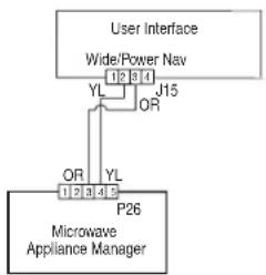
flowchart
graph TD
    A["User Interface"] --> B["Wide/Power Nav"]
    B --> C["YL 12 14"]
    B --> D["J15"]
    D --> E["OR"]
    E --> F["P26"]
    F --> G["Microwave Appliance Manager"]
    style A fill:#f9f,stroke:#333
    style G fill:#ccf,stroke:#333
- If harness is correct, replace the Microwave Appliance Manager.
- Reassemble all parts and panels before operating.
- Plug in oven or reconnect power.
- If the error appears again, unplug or disconnect power and replace HMI-Central/UI board.
- Reassemble all parts and panels before operating.
-
Plug in oven or reconnect power.
-
Follow the on-screen prompts to select the model number if the UI was replaced.
- Verify operation is normal. Enter the Diagnostics menu, select "Error Diagnostics," and clear the history.
| FAILURE(Left-most 2 Clock digits) | ERROR(Right-most 2 Clock digits) | LIKELY FAILURE CONDITION |
| F8 | E0 Product not wired correctly | |
| E1 Low fan speed overspeed | ||
| E2 High fan speed underspeed | ||
| E3 High fan speed overspeed | ||
LOW FAN SPEED MESSAGE ON SINGLE/DOUBLE: The product is experiencing a problem and can no longer be used.
SUGGESTED CORRECTIVE ACTION PROCEDURE
- Unplug oven or disconnect power.
- Wait for at least 30 seconds.
- Plug in oven or reconnect power.
- Enter Diagnostics mode and navigate to the Component Activation list.
- Turn on the Cooling Fan Low Speed.
- Check for proper voltage input at P5-5 and neutral for high speed fan, P5-4 and neutral for low speed fan when cooling fan should be running by completing following steps.
- Unplug oven or disconnect power.
- Connect voltage measurement equipment.
- Plug in oven or reconnect power. Measure voltage and confirm voltage reading is 120 V. If it is not, unplug oven or disconnect power and go to Step 13. If it is, go to Step 10.
- Check for proper voltage input at P4-1 and P4-2 and confirm voltage reading is 5 VDC. If it is not, unplug oven or disconnect power and go to Step 13. If it is, go to Step 11.
- Unplug oven or disconnect power.
- Replace cooling fan. Go to Step 15.
- Check integrity of all harness wires and connections between the oven appliance manager and the cooling fan. Ensure no shorted wires to chassis. If the wiring is pinched or damaged, replace the cooling fan harness. Go to Step 15. If the wiring is good, go to Step 14.
- Replace oven appliance manager. Go to Step 15
FOR SERVICE TECHNICIAN'S USE ONLY
- Replace all parts and panels before operating.
- Plug in oven or reconnect power.
- Enter into Diagnostics mode and verify that fan speed is running within oven. (High speed: 1000-3300, Low speed: 400-3000)
Once Fan Speed is completed, navigate back to the activation list and activate the Cooling Fan High Speed and return to "More Information" screen for fan speed.
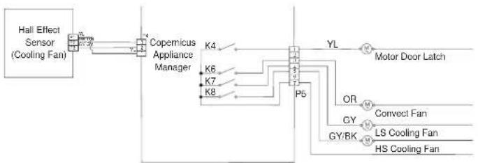
flowchart
graph LR
    A["Hall Effect Sensor (Cooling Fan)"] --> B["Copemicus Appliance Manager"]
    B --> C["K4"]
    B --> D["K6"]
    B --> E["K7"]
    B --> F["K8"]
    C --> G["P5"]
    D --> G
    E --> G
    F --> G
    G --> H["Motor Door Latch"]
    I["OR"] --> G
    J["GY"] --> G
    K["GS"] --> G
    L["LS"] --> G
    M["HS"] --> G
FAILURE ERROR LIKELY FAILURE CONDITION
F9 E0 Product not wired correctly
SUGGESTED CORRECTIVE ACTION PROCEDURE
NOTE: Before starting any test, cycle power to the oven (power Off, wait 10 seconds, and then power On).
PROCEDURE: Before proceeding, verify the error code by entering the Diagnostics menu and selecting "Error Diagnostics."
- Unplug oven or disconnect power.
- Access the electrical wiring from the house power supply to the oven.
- Check house wiring to the product. Check to see if the neutral connection is switched with L1 or L2 (refer to the installation instructions for product wiring).
- Reassemble all parts and panels before operating.
- Plug in oven or reconnect power.
- Verify operation is normal by running a cooking function. Enter Diagnostics menu, select "Error Diagnostics," and clear the history.
Microwave Oven Components
Component Locations
Upper Microwave Oven
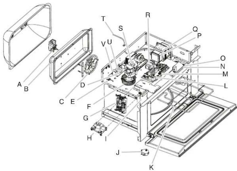
text_image
Exploded view diagram of an electronic device with labeled components from A to QA. Convect motor
B. Convect thermostat (behind cover)
C. Convect element
D. Line filter
E. Humidity sensor
F. Magnetron fan motor
G. Copernicus appliance manager (lower oven)
H. Switch mode power supply (SMPS)
1. Secondary interlock switch
J. Turntable motor
K. Broil element
L. Microwave appliance manager
M. Cavity halogen lamp
N. Primary interlock switch
O. Monitor interlock switch
P. Magnetron thermistor
Q. Magnetron
R. Microwave light transformer
S. Microwave inverter
T. Cavity temperature sensor
U. Grill thermostat
V. Cavity thermostat
Not shown: Monitor fuse, 20 A line fuse
Lower Oven
FOR SERVICE TECHNICIAN'S USE ONLY
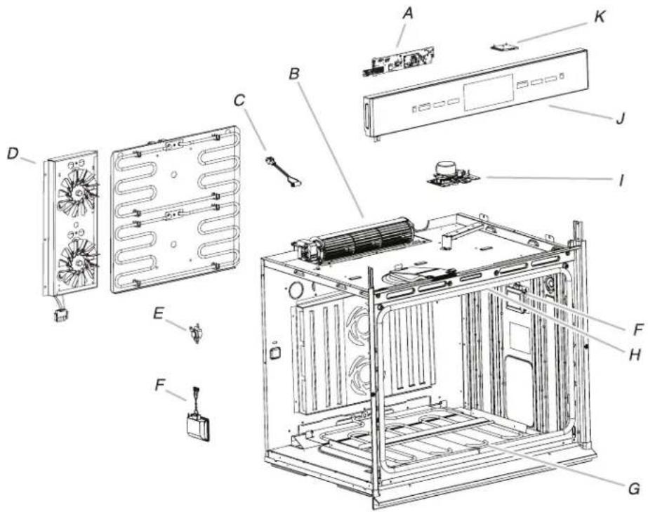
text_image
Exploded view diagram of a computer system with labeled components from fan to batteryA. HMI-Central/UI board
B. Cooling fan
C. Oven temperature sensor
D. Convection assembly
E. Temperature limiter
F. Light assembly
G. Bake element (hidden)
H. Broil element
1. Door lock assembly
J. Control panel assembly
K. WiFi antenna
Cooling Fan Relay Logic
| Oven High Speed Blower (Main/Upper or Lower) | Oven Low Speed Blower (Main/Upper or Lower) | |
| Oven Cooking - Cold - O | ||
| Oven Cooking - Warm - O | ||
| Oven Cooking - Hot O - | ||
| Oven Self-Clean O - |
LEGEND
| Cold Cavity Temperature is less than 212°F (100°C) |
| Warm Cavity Temperature is between 212°F and 599°F (100°C and 315°C) |
| Hot Cavity Temperature is greater than 599°F (315°C) |
FOR SERVICE TECHNICIAN'S USE ONLY
| Mode Bake Broil | Upper Convect Ring | Lower Convect Ring | Upper Convect Fan | Lower Convect Fan | ||
| Convect Frozen Pizza C C C C O O | ||||||
| Convect Pastry C C C C C C | ||||||
| Convect Slow Roast 12 hrs C C C C O O | ||||||
| Convect Slow Roast 8 hrs C C C C O O | ||||||
| Convect Slow Roast 4 hrs C C C C O O | ||||||
| Convect Roast C C C C O O | ||||||
| Convect Broil - C -- | C C | |||||
| Convect Bake | C C C C C C | |||||
| Convect Bake- Rapid Preheat | C C C C C C | |||||
| Bake | C C C C C C | |||||
| Broil | - | C | - | - | - | - |
| Keep Warm | C | C | - | - | C | C |
| Rapid Proof | C | C | - | - | - | - |
| Proof | C | C | - | - | - | - |
| No Preheat | C C C C C C | |||||
| True Convect | C C C C C C | |||||
| Self Clean | C | C | - | - | - | - |
LEGEND
| Relay Off | Relay Cycles | Relay On | Not Available |
| - | C | O | NA |
Component Testing Chart - Oven
To properly check for voltage, complete the following steps:
- Unplug oven or disconnect power.
- Connect voltage measurement equipment to check points.
- Plug in oven or reconnect power and confirm voltage reading.
- Unplug oven or disconnect power.
Component Serviceable Side Check Points Copernicus Results-Resistance Results-Voltage
| Lights Front P7-1 to L1 (J8-1) 0-40 Ω 120 V | ||||
| Latch Switch Front P3-7 to P3-5 Open circuit | ||||
| Door Switch Front P3-6 to P3-5 | Closed circuit with oven door closed | |||
| Latch Motor | Front | P5-1 to N (J8-2) | 500 to 3000 Ω | 120 V motor running |
| Oven Temperature Sensor | Front P3-1 to P3-2 1075 Ω at 68°F (20°C) DLB | |||
| Meat Probe | Side | P3-3 to P3-4 9876-10075 Ω | ||
| Blower Motor - High Speed | Rear | PX2-2 to L1 (J8-1) | 15 to 23 Ω | 120 V motor running |
| Blower Motor - Low Speed | Rear | P7-2 to L1 (J8-1) | 15 to 23 Ω | 120 V motor running |
| Thermal Limiter | Rear | PX3-1 to L2 (Main line) | Closed circuit | 0 V closed, N/A open |
| Upper Convection Fan - High Speed | Rear | P5-3 to N (J8-2) | 15 to 22 Ω | 120 VAC motor running |
| Upper Convection Fan - Low Speed | Rear | P5-2 to N (J8-2) | 17 to 25 Ω | 120 VAC motor running |
| Lower Convection Fan - High Speed | Rear | P5-5 to N (J8-2) | 15 to 22 Ω | 120 VAC motor running |
| Lower Convection Fan - Low Speed | Rear | P5-4 to N (J8-2) | 17 to 25 Ω | 120 VAC motor running |
FOR SERVICE TECHNICIAN'S USE ONLY
| Component Serviceable Side Check Points Copernicus Results-Resistance Results-Voltage | |||
| Upper Convection Element Front PX1-3 to PX3-2 15.2 to 17.3 Ω | 240 VAC Convectioncycle operating | ||
| Lower Convection Element Front PX2-4 to PX3-2 15.2 to 17.3 Ω | 240 VAC Convectioncycle operating | ||
| Bake Element Rear PX1-1 to PX3-2 19.0 to 21.6 Ω 240 V Bake cycle operating | |||
| Broil Element Front PX4-2 to PX3-2 13.5 to 14.92 Ω 240 V Broil cycle operating | |||
| User Interface Board Front J15-2 to J15-4 N/A 14 VDC | |||
| Copernicus Appliance Manager | Side (Combo) | P1-2 to P1-5 | N/A 14 VDC |
NOTES:
■ Disconnect the harness from the board before performing measurements.
■ See the following table for connector pin identification.
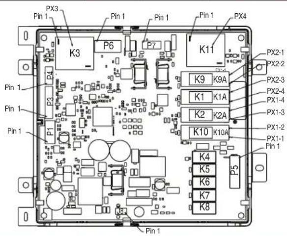
Copernicus Appliance Manager Harness Connector Pin Copernicus Appliance Manager Pin
Component Testing Chart - Microwave
| Component Serviceable Side Procedure Results - Resistance Component Location | ||||
| Appliance Manager Top Check wiring to MW microwave appliance manager: | G | |||
| 1. Unplug the microwave oven or disconnect power.2. Visually inspect connectors on the microwave appliance manager, P1, P2, P8, P21, P22, P23, P26, P354, P355 and the top connectors (relays 4903, 4904 and 4905) to see whether there are signs of overheating or any signs of failure due to loose wires, bad crimping, etc.3. Reassemble all parts and panels before operating.4. Plug in microwave oven or reconnect power. | ||||
| Cavity Thermostat | Top | 1. Unplug microwave oven or disconnect power.2. Remove wire leads.3. Measure resistance.4. Replace wire leads.5. Reassemble all parts and panels before operating.6. Plug in microwave oven or reconnect power. | Normal = ContinuityAbnormal = Infinite | V |
| Magnetron Fan Motor | Top | 1. Unplug microwave oven or disconnect power.2. Remove wire leads.3. Measure resistance (ohmmeter scale: Rx1).4. Replace wire leads.5. Reassemble all parts and panels before operating.6. Plug in microwave oven or reconnect power. | Normal = 15 ΩAbnormal = Infinite | F |
| Turntable Motor | Bottom | 1. Unplug microwave oven or disconnect power.2. Remove wire leads.3. Measure resistance (ohmmeter scale: Rx1).4. Replace wire leads.5. Reassemble all parts and panels before operating.6. Plug in microwave oven or reconnect power. | Normal =2500 Ω (approximately)Abnormal = Infinite | J |
| Component Serviceable Side Procedure Results - Resistance Component Location | |||
| Monitor Fuse Top 1. Unplug microwave oven or disconnect power.2. Remove wire leads.3. Measure resistance.4. Replace wire leads.5. Reassemble all parts and panels before operating.6. Plug in microwave oven or reconnect power. | Normal = ContinuityAbnormal = Infinite | Not shown | |
| MW Light Transformer Top | 1. Unplug microwave oven or disconnect power.2. Remove wire leads.3. Measure resistance (ohmmeter scale: Rx1).4. Replace wire leads.5. Reassemble all parts and panels before operating.6. Plug in microwave oven or reconnect power. | Primary Winding = 40 (approximately)Secondary Winding = 0.4 (approximately) | R |
| Line Fuse Top 1. Unplug microwave oven or disconnect power.2. Remove wire leads.3. Measure resistance.4. Replace wire leads.5. Reassemble all parts and panels before operating.6. Plug in microwave oven or reconnect power. | Normal = ContinuityAbnormal = Infinite | Not shown | |
FOR SERVICE TECHNICIAN'S USE ONLY
| Component Serviceable Side Procedure Results - Resistance Component Location | |||
| Primary Interlock Switch | Top Test 1: | Test 1: | N |
| Door Open = Infinite. | |||
| Door Closed = Continuity. | |||
| Test 2: | |||
| Door Open = Continuity. | |||
| Door Closed = Infinite | |||
| Secondary Interlock Switch | Top 1. Unplug microwave oven or disconnect power. | Door Open = Continuity. | I |
| 2. Disconnect the wires at the Secondary Interlock Switch. | Door Closed = Infinite | ||
| 3. Check from the common terminal (blue wire) to the normally open terminal (white wire). | |||
| 4. Reconnect the wires at the Secondary Interlock Switch. | |||
| 5. Reassemble all parts and panels before operating. | |||
| 6. Plug in microwave oven or reconnect power. | |||
| Monitor Interlock Switch | Top 1. Unplug microwave oven or disconnect power.2. Disconnect the wires at the Monitor Interlock Switch.3. Check from the common terminal (yellow wire) to the normally closed terminal (blue wire).4. Reconnect the wires at the Monitor Interlock Switch.5. Reassemble all parts and panels before operating.6. Plug in microwave oven or reconnect power. | Door Open = Continuity. O Door Closed = Infinite | |
| Halogen Light Top 1. | Unplug microwave oven or disconnect power.2. Remove wire leads.3. Measure resistance.4. Replace wire leads.5. Reassemble all parts and panels before operating.6. Plug in microwave oven or reconnect power. | Normal = approximately M 3 Ω Abnormal = Infinite | |
| Inverter Top Check wiring to MW inverter: | S | ||
FOR SERVICE TECHNICIAN'S USE ONLY
| Component Serviceable Side Procedure Results - Resistance Component Location | ||||
| Line Filter Top 1. Unplug microwave oven or disconnect power. | P31 to P32, P33 to P34Normal >= 300 kΩAbnormal< = 100 kΩP31 to P34, P32 to P33Normal = 0 ΩAbnormal>= 100 kΩ | D | ||
| Humidity Sensor | Top | 1. Unplug microwave oven or disconnect power. | Normal = 2.8 kΩ(approximately) at77°F +/- 10°F(25°C +/- 10°C)Abnormal = Infinite. | E |
| 2. Remove the 3-pin connector from MW Appliance Manager. | ||||
| 3. Measure resistance across pins 1 and 3 and across pins 2 and 3. | ||||
| 4. Replace the 3-pin connector from MW Appliance Manager. | ||||
| 5. Reassemble all parts and panels before operating. | ||||
| 6. Plug in microwave oven or reconnect power. | ||||
| Magnetron Thermistor 1. Unplug microwave oven or disconnect power. | Normal = 10 kΩ(approximately) at77°F +/- 10°F(25°C +/-10°C)Abnormal = Infinite. | P | ||
| Grill Thermostat | Top | 1. Unplug microwave oven or disconnect power. | Normal = ContinuityAbnormal = Infinite | U |
| 2. Remove wire leads. | ||||
| 3. Measure resistance. | ||||
| 4. Replace wire leads. | ||||
| 5. Reassemble all parts and panels before operating. | ||||
| 6. Plug in microwave oven or reconnect power. | ||||
| Component Serviceable Side Procedure Results - Resistance Component Location | |||
| Convect Thermostat Rear 1. Unplug microwave oven or disconnect power.2. Remove wire leads.3. Measure resistance.4. Replace wire leads.5. Reassemble all parts and panels before operating.6. Plug in microwave oven or reconnect power. | Normal = ContinuityAbnormal = Infinite | B | |
| Broil Element Rear 1. Unplug microwave oven or disconnect power.2. Remove wire leads.3. Measure resistance.4. Replace wire leads.5. Reassemble all parts and panels before operating.6. Plug in microwave oven or reconnect power. | Normal = 9 ΩAbnormal = Infinite | K | |
| Convect Element Rear 1. Unplug microwave oven or disconnect power.2. Remove wire leads.3. Measure resistance.4. Replace wire leads.5. Reassemble all parts and panels before operating.6. Plug in microwave oven or reconnect power. | Normal = 12 ΩAbnormal = Infinite | C | |
| Cavity Temperature Sensor Rear 1. Unplug microwave oven or disconnect power.2. Remove wire leads.3. Measure resistance.4. Replace wire leads.5. Reassemble all parts and panels before operating.6. Plug in microwave oven or reconnect power. | Normal = 230 kΩ (approximately) at 77°F ±10°F (25°C ±10°C)Abnormal = Infinite | T | |
| Convect Fan Motor Rear 1. Unplug microwave oven or disconnect power.2. Remove wire leads.3. Measure resistance.4. Replace wire leads.5. Reassemble all parts and panels before operating.6. Plug in microwave oven or reconnect power. | Normal = 48 ΩAbnormal = Infinite | A | |
FOR SERVICE TECHNICIAN'S USE ONLY
For patent information, please see Pat. www.patent-listing.com W11398798A
NOTE: This sheet contains important Technical Service Data.
FOR SERVICE TECHNICIAN ONLY
DO NOT REMOVE OR DESTROY
W11398798A
©2020 All rights reserved.
08/20
FOR SERVICE TECHNICIAN'S USE ONLY
text_image
DIAGNOSTICS HOME Error Diagnostics Troubleshoot Error Codes Component Activation Bake, Broil, Convection, Fans... Sensors & Switches OKtext_image
Exploded view diagram of a refrigerator internal components with labeled parts A through Qtext_image
Exploded view diagram of a computer system with labeled components including fan, chassis, and chassis frametext_image
Broke 1 P3 K3 P6 P7 Broke 1 Broke 1 Broke 1 P1 K10 K10A K9 K9A K1 K1A K2 K2A K4 K5 K6 K7 K8 P3 P5 Broke 1 Broke 1 Broke 1 Broke 1 Broke 1 Broke 1 Broke 1 Broke 1 Broke 1 Broke 1 Broke 1 Broke 1 Broke 1 Broke 1 Broke 1 Broke 1 Broke 1 Broke 1 Broke 1 Broke 1 Broke 2-1 Broke 2-2 Broke 2-3 Broke 2-4 Broke 2-5 Broke 2-6 Broke 2-7 Broke 2-8 Broke 2-9 Broke 2-10 Broke 2-11 Broke 2-12 Broke 2-13 Broke 2-14 Broke 2-15 Broke 2-16 Broke 2-17 Broke 2-18 Broke 2-19 Broke 2-20 Broke 2-21 Broke 2-22 Broke 2-23 Broke 2-24 Broke 2-25 Broke 2-26 Broke 2-27 Broke 2-28 Broke 2-29 Broke 2-30PX1-1 J12
PX1-2 J16
PX1-3 J13
PX1-4 J17
PX2-1 J19
PX2-2 J15
PX2-3 J18
PX2-4 J14