
TAA131 - Temperature transmitter IFM - Free user manual and instructions
Find the device manual for free TAA131 IFM in PDF.

| Brand | IFM |
| Model | TAA131 |
| Product type | AS-i analog temperature transmitter |
| Measuring range | -10 … 150 °C / 14 … 302 °F |
| Measuring element | 1 x Pt 1000 according to DIN EN 60751, class A |
| Power supply | Via AS-i network, voltage 26.5 … 31.6 V, consumption < 25 mA |
| Process connection | G 1/4" |
| Network connection | M12 connector, 2 wires (brown, blue) |
| AS-i address | 1 … 31 (adjustable), factory address 0 |
| Slave profile | S-7.3.C (V2.1 analog) |
| LED display | Green: operation; Red: fault or internal error |
| Accuracy | ± 0.1 K at 60 °C; ± 0.3 K over full range |
| Resolution | < 0.05 °C / 0.09 °F |
| Repeatability | ± 0.1 °C / 0.18 °F |
| Response time | T05 = 1 s, T09 = 3 s |
| Maximum fluid temperature | 150 °C (duration < 40 min) |
| Ambient temperature | -25 … 70 °C |
| Storage temperature | -40 … 100 °C |
| Maximum pressure | 400 bar (admissible overpressure) |
| Protection rating | IP 69K, class III |
| Shock/vibration resistance | 50 g (shock), 20 g (vibration 10-2000 Hz) |
| Housing material | Stainless steel 316L, 304, 303, PAM; wetted parts: Stainless steel 316L |
| Dimensions | See dimension drawing in manual (approx. 80 mm long) |
| Commissioning | Mechanical mounting, addressing, LED check |
Frequently Asked Questions - TAA131 IFM
User questions about TAA131 IFM
0 question about this device. Answer the ones you know or ask your own.
Ask a new question about this device
Download the instructions for your Temperature transmitter in PDF format for free! Find your manual TAA131 - IFM and take your electronic device back in hand. On this page are published all the documents necessary for the use of your device. TAA131 by IFM.
USER MANUAL TAA131 IFM
Operating instructions
Notice utilisateurs
efector600®
Temperaturtransmitter
Temperature transmitter
natural_image
Technical line drawing of a mechanical component with a cylindrical shaft and flanged top (no text or symbols)| ContentsFunction and features ...... page 8Installation ...... page 9Addressing ...... page 9Mechanical installation ...... page 9Connection to the AS-i system ...... page 9Set-up / operation ...... page 10Representation of measured values ...... page 10Fault handling ...... page 10Data bits ...... page 11Technical data ...... page 12Scale drawing ...... page 19 | ENGLISH |
natural_image
Technical line drawing of a mechanical assembly with a central shaft and mounting base (no text or symbols)flowchart
graph TD
    A["1 BN"] --> B["ASI+"]
    C["3 BU"] --> D["ASI-"]
Functions and features
The temperature transmitter operates as a single slave in the AS-i network (slave profile S-7.3.C).
- It detects the current system temperature,
- converts it into digital coded analog values
- and transfers these values to the control level (master, controller or host).
Analog value representation
Signed 16-bit value as two's complement value. The analog value transmission protocol is specified in the slave profile 7.3.
A master of AS-i version 2.11 detects the slave automatically. The analog value transmission to slave profile 7.3 is then supported. Masters of AS-i version 2.0 require a special driver (additional function block, available as an accessory).
- Measuring range: -10 ... 150°C / 14 ... 302°F
- Measuring element: Pt 1000 to DIN EN 60751, class A
• Temperature resistance
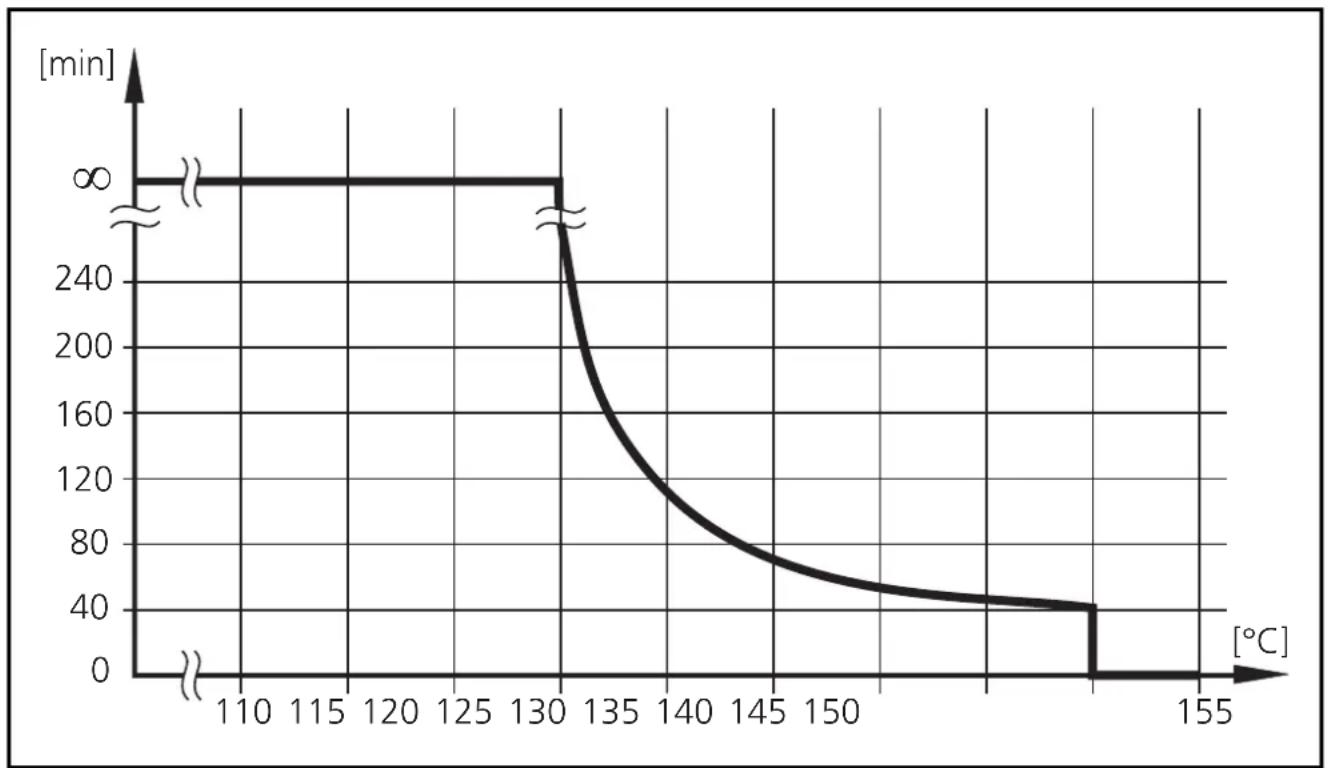
line
| Temperature [°C] | Time [min] | | ---------------- | ---------- | | 110 | 0 | | 130 | 0 | | 135 | 240 | | 150 | 80 | | 155 | 40 |Maximum operation time depending on the medium temperature
Installation
Addressing
You can address the sensor by using an addressing unit, the master or by means of the AS-i software of the host (the components must support AS-i version 2.11).
Assign an address between 1 and 31. At the factory the address is set to 0.
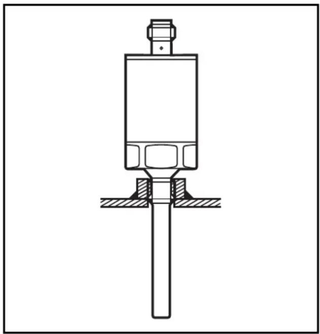
Mechanical installation
Mount the unit to G ^1/4 process connection.
natural_image
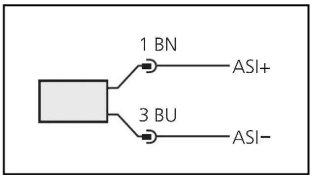
Technical line drawing of a mechanical assembly with a central shaft and mounting base (no text or symbols)Connection to the AS-i system
Connect the sensor with the AS-i system by using the M12 connector. Voltage is supplied via the AS-i network. Wiring:
flowchart
graph TD
    A["Square Block"] --> B["1 BN"]
    A --> C["3 BU"]
    B --> D["ASI+"]
    C --> E["ASI-"]
Core colours of ifm sockets:
1 = BN (brown),
3 = BU (blue)
Referring to UL: For use on a low voltage circuit with overcurrent protection in accordance with UL873 Tab. 28.1 or Imax = 100/Ub (Ub = voltage of the circuit).
Installation and set-up / Operation
After mounting and wiring check whether the unit operates correctly. Indication at the sensor in the operating mode:
| LED green ON = unit is then ready for operation | |
| LED red | ON = no communication |
| FLASHING = internal faultis transferred to the master as periphery fault | |
Slave profile
| I/O Code [hex] 7 | |
| ID Code [hex] | 3 |
| Extended ID2 Code [hex] C | |
| ID1 Code code for temperature values [hex] 6 | |
| Slave address (factory setting) 0 |
Representation of measured values by data bits D16 ... D1
| Overflow (measured value outside the value range), overflow bit is set | 32767 |
| Overrange (measured value is valid but outside the nominal range) | 1500 ... 1650 |
| Nominal Range (measured value in the specified value range) | -100 ... 1500 |
| Underrange (measured value is valid but outside the nominal range) | -150 ... -100 |
| Underflow (measured value outside the value range), overflow bit is set | -32768 |
| Representation of measured values following ID1 | °C × 0.1 |
| Increments min. 0.1 |
Fault handling
Automatic fault handling according to AS-i version 2.1.
- Power-up: During power-up the data is marked faulty until a valid data transfer is guaranteed.
• After interruption of the data communication the watchdog function starts communication again.
- Data triple in wrong order: If a fault occurs, the sensor sets its data triples to 0 (invalid) and waits for a new triple sequence.
Data bits
During one transmission cycle the following data is transferred in data triples.
| Extension Bits | E3 | Only 1 measuring channel is used. The bits E3, E2 and E1 are always 0. |
| E2 | ||
| E1 | ||
| User Information Data | D16 | The analog values measured are transferred via the data bits D1 ... D16 according to slave profile 7.3. |
| D15 | ||
| D14 | ||
| D13 | ||
| D12 | ||
| D11 | ||
| D10 | ||
| D9 | ||
| D8 | ||
| D7 | ||
| D6 | ||
| D5 | ||
| D4 | ||
| D3 | ||
| D2 | ||
| Additional Information Bits | D1 | |
| O | Overflow-Bit | |
| V | Valid-Bit |
Overflow-Bit:
O = 0: measured value is within the value range
O = 1: measured value is outside the value range
(above max. value for overload or below minimum value for overload)
Valid-Bit:
V = 0: measured value not valid
V = 1: measured value valid
Technical data
| Operating voltage [V]......18 ... 31.6 DC (AS-i)reverse polarity protection / overload protectionCurrent consumption [mA]......< 25 |
| Measuring element......1 x Pt 1000 to DIN EN 60751, class AAccuracyAnalogue signal......± 0.1 K (60°C / 140°F)± 0.3 K (-10...150°C / 14...302°F)Repeatability [°C / °F].......± 0.1 / 0.18Resolution [°C / °F]......< 0.05 / 0.09Dynamic response (according to DIN EN 60751) [s]...... T_05 = 1 / T_09 = 3 |
| Housing material......stainless steel (316S12); stainless steel (304S15);stainless steel (303S22); PAMaterials (wetted parts)......stainless steel (316S12)Max. medium temperature [°C]......150°C (< 40 min.)Operating temperature [°C]......-25 ... +70Storage temperature [°C]......-40 ... +100Permissible overl. pressure [bar]......400 |
| Protection......IP 69KProtective class......IIIShock resistance [g]......50 (DIN / IEC 68-2-27, 11ms)Vibration resistance [g]......20 (DIN / IEC 68-2-6, 10 - 2000 Hz)EMCEN 61000-4-2 ESD:......4 / 8 KVEN 61000-4-3 HF radiated:......10 V/mEN 61000-4-4 Burst:......2 KVEN 61000-4-5 Surge:......0.5 / 1 KVEN 61000-4-6 HF conducted:......10 V |
natural_image
Technical line drawing of a mechanical assembly with a central shaft and mounting base (no text or symbols)Brand : IFM
Model : TAA131
Category : Temperature transmitter