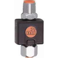
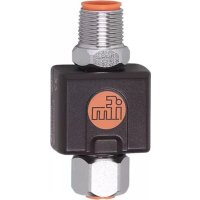
TP3237 - Electric converter IFM - Free user manual and instructions
Find the device manual for free TP3237 IFM in PDF.


User questions about TP3237 IFM
0 question about this device. Answer the ones you know or ask your own.
Ask a new question about this device
Download the instructions for your Electric converter in PDF format for free! Find your manual TP3237 - IFM and take your electronic device back in hand. On this page are published all the documents necessary for the use of your device. TP3237 by IFM.
USER MANUAL TP3237 IFM
Operating instructions
Measuring signal converter for temperature sensors
TP323x
Contents
1 Preliminary note.... 3
1.1 Symbols used.... 3
2 Safety instructions 4
2.1 Cybersecurity 4
3 Transport, handling and storage 5
4 Intended use 6
5 Function 7
5.1 IO-Link 7
6 Installation.... 8
7 Electrical connection 9
8 Operating and display elements.... 10
9 Parameter setting 11
9.1 Analogue signal.... 11
9.2 Error behaviour of the outputs 12
9.3 Zero calibration 12
9.4 Device information 13
10 Factory setting.... 14
1 Preliminary note
You will find instructions, technical data, approvals and further information using the QR code on the unit / packaging or at documentation.ifm.com.
1.1 Symbols used
Requirement
Instruction
Reaction, result
bold Designation of keys, buttons or indications
→ Cross-reference without link
→ Cross-reference with link


Important note
Non-compliance may result in malfunction or interference
Information
Supplementary note
2 Safety instructions
- The unit described is a subcomponent for integration into a system.
- The system architect is responsible for the safety of the system.
-
The system architect undertakes to perform a risk assessment and to create documentation in accordance with legal and normative requirements to be provided to the operator and user of the system. This documentation must contain all necessary information and safety instructions for the operator, the user and, if applicable, for any service personnel authorised by the architect of the system.
-
Read this document before setting up the product and keep it during the entire service life.
- The product must be suitable for the corresponding applications and environmental conditions without any restrictions.
- Only use the product for its intended purpose (→ Intended use).
- If the operating instructions or the technical data are not adhered to, personal injury and/or damage to property may occur.
- The manufacturer assumes no liability or warranty for any consequences caused by tampering with the product or incorrect use by the operator.
- Installation, electrical connection, set-up, operation and maintenance of the product must be carried out by qualified personnel authorised by the machine operator.
- Protect units and cables against damage.
2.1 Cybersecurity
Installation
The device is suitable for operation in a secure environment according to IEC 62443-1-1.
The device was designed for operation behind a firewall.
▶ Carry out a risk assessment of the system according to IEC 62443-1-1.
▶ Take measures to ensure physical security.
Operation
▶ Observe the security functions described in the product documentation and the recommendations for their use.
Maintenance
- ▶ Back up system configuration and system data in accordance with your company’s change management processes.
Decommissioning
▶ Ensure that no sensitive information can fall into unauthorised hands.
▶ Always reset the system settings to the factory settings before decommissioning the device.
3 Transport, handling and storage
▶ Store the device in its original packaging.
▶ When the device is to be stored again, use the original packaging.
▶ Otherwise, provide unused connections with either a mating connector or a protective cap and pack the device in suitable packaging.
▶ Observe the permissible ambient conditions for the device during storage (→ Technical data).
4 Intended use
The device monitors the system temperature in machines and systems in conjunction with a connected temperature probe.
The device provides the measured value via an analogue signal. In addition, a digital signal can be provided via the IO-Link interface.
Connectable temperature probes:
• Temperature sensors TM, TS, TSM, TT.
• RTD resistance thermometers (Pt 100 or Pt 1000).
5 Function
The device can be operated in analogue mode or additionally in IO-Link mode.
In analogue mode, the device provides the measured temperature value via an analogue signal of 4...20 mA or 20...4 mA.
5.1 IO-Link
IO-Link is a communication system for connecting intelligent sensors and actuators to automation systems. IO-Link is standardised in the IEC 61131-9 standard.

General information on IO-Link at io-link.ifm

Input Output Device Description (IODD) with all parameters, process data and detailed descriptions of the device at documentation.ifm.com
IO-Link offers the following advantages:
• Interference-free transmission of all data and process values
• Parameter setting in the running process or presetting outside the application
- Parameters for identifying the connected devices in the system
• Additional parameters and diagnostic functions
• Automatic backup and restore of parameter sets in case of device replacement (data storage)
- Logging of parameter sets, process values and events
• Device description file (IODD - Input Output Device Description) for easy project planning
• Standardised electrical connection
- Remote maintenance
6 Installation
▶ Connect the device to the temperature probe.

Fig. 1: Connecting the temperature probe
1: Connection for voltage supply and output signals
2: Connection for temperature probe
7 Electrical connection

The unit must be connected by a qualified electrician.
Observe the national and international regulations for the installation of electrical equipment. Voltage supply according to SELV, PELV.

IP rating is only assured with suitable connectors that have at least the same IP rating class as the unit.
▶ Disconnect power.
▶ Connect the unit as follows:
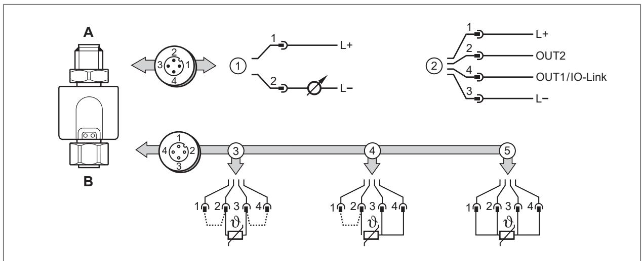
Fig. 2: Electrical connection
| A (4-pole M12 connector): voltage supply and output signals | |
| 1 | Connection as analogue device:Pin 2: analogue signal for temperature |
| 2 | Connection as analogue/IO-Link device:Pin 4 (OUT1): IO-LinkPin 2 (OUT2): analogue signal for temperature |
| B (4-pole M12 socket): connection for temperature probe | |
| 3 | Connection of a 2-wire temperature probe.• Links between 1/2 and 3/4. |
| 4 | Connection of a 3-wire temperature probe.• Link between 1/2. |
| 5 | Connection of a 4-wire temperature probe. |

The device detects the connected temperature probe and configures itself accordingly.
8 Operating and display elements
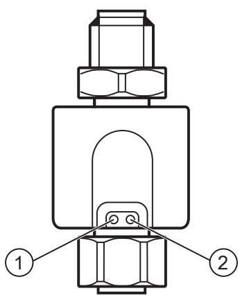
Fig. 3: Indicators
1: LED is on in case of operation as 3-wire device, IO-Link communication is possible.
2: LED is on in case of a load on the analogue output.
9 Parameter setting
The parameters are set via the IO-Link interface.
Parameters can be set before installation or during operation.

If you change parameters during operation, this will influence the function of the plant.
▶ Ensure that there will be no malfunctions in your plant.
During parameter setting the unit remains in the operating mode. It continues to monitor with the existing parameter until the parameter setting has been completed.

Depending on the parameter setting, the parameters available in the menu may change.
Requirements for parameter setting via the IO-Link interface:
√ A suitable parameter setting software, e.g. ifm moneo|configure
√ The Input Output Device Description (IODD) for the device, see documentation.ifm.com
√ One IO-Link master
▶ Connect the IO-Link master to a parameter setting software.
▶ Set the port of the master to the IO-Link operating mode.
▶ Connect the device to a free port of the IO-Link master.
▷ The unit switches to IO-Link mode.
▶ Change parameter settings in the software.
▶ Write parameter settings to the unit.

Notes on parameter setting ➕ Manual of the parameter setting software
9.1 Analogue signal
The device provides an analogue signal proportional to the process value.
The analogue signal is invertible:
• 4...20 mA for setting ou2 = I
• 20...4 mA for setting ou2 = InEG
Within the measuring range the analogue signal is between 4...20 mA.
The measuring range is scalable: the parameters ASP and AEP allow for the measuring range to be limited.

Minimum distance between ASP and AEP = 5 °C or 9 °F.
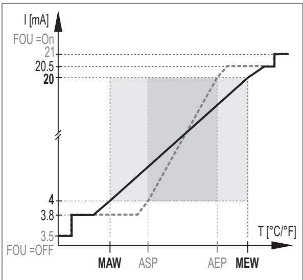
Fig. 4: Analogue output with setting OU2 = I

Fig. 5: Analogue output with setting OU2 = INeg
| MAW: | Initial value of the measuring range | Analogue characteristic curve with unscaled measuring range: |
| MEW: | Final value of the measuring range | |
| ASP: | Analogue start point with scaled measuring range | Analogue characteristic curve with scaled measuring range: |
| AEP: | Analogue end point with scaled measuring range |
Tab. 1: Explanation of the figures
9.2 Error behaviour of the outputs
The behaviour of the analogue output OUT2 in the event of an error can be set via the parameter FOU. The following signals are output in the event of an error:
• On: The analogue signal goes to 21 mA.
• OFF: The analogue signal goes to 3.5 mA.
9.3 Zero calibration
The combination of temperature probe and measuring signal converter can lead to measurement inaccuracies, particularly depending on the respective ambient conditions.
If there is a systematic deviation between the measured value and the actual process value, this measurement inaccuracy can be corrected using the correction factor cOF.
Ein Leitungsfehler beim elektrischen Anschluss eines 2- oder 3-Leiter-Temperaturfühlers kann ebenfalls über den Korrekturfaktor cOF korrigiert werden.
The internal zero point is shifted by the set value.

Fig. 6: Zero point calibration (calibration offset); example
1: Output signal
2: Process value
V0: Curve of measured values at factory setting
V1: Curve of measured values after offset by +1°C
V2: Curve of measured values after offset by -1°C
Setting range ± 10 °C in steps of 0,1 °C
9.4 Device information
Unalterable device information is stored on the unit. This includes:
- Product name
- Product family
- Manufacturer
- Manufacturer ID
- Device ID
- Serial number
• Hardware / firmware revision - Description
In addition, further freely definable tags with a maximum length of 32 characters can be assigned to the unit via the IO-Link interface using suitable parameter setting software. This includes:
- application-specific tag
- function tag
- location tag
10 Factory setting
| Parameter | Factory setting | User settings | |||
| TP3231 | TP3232 | TP3233 | TP3237 | ||
| OU2 | I | I | I | I | |
| ASP | -50 °C | -50 °C | 0 °F | 0 °C | |
| AEP | 150 °C | 300 °C | 300 °F | 100 °C | |
| COF | 0.0 °C | 0.0 °C | 0.0 °C | 0.0 °C | |
| FOU2 | OFF | OFF | OFF | OFF | |
- 1 PRELIMINARY NOTE
- 1.1 SYMBOLS USED
- 2 SAFETY INSTRUCTIONS
- 2.1 CYBERSECURITY
- 3 TRANSPORT, HANDLING AND STORAGE
- 4 INTENDED USE
- 5 FUNCTION
- 5.1 IO-LINK
- 6 INSTALLATION
- 7 ELECTRICAL CONNECTION
- 8 OPERATING AND DISPLAY ELEMENTS
- 9 PARAMETER SETTING
- 9.1 ANALOGUE SIGNAL
- 9.2 ERROR BEHAVIOUR OF THE OUTPUTS
- 9.3 ZERO CALIBRATION
- 9.4 DEVICE INFORMATION
- 10 FACTORY SETTING
Brand : IFM
Model : TP3237
Category : Electric converter