
WS9037UIT - Weather Station LA CROSSE TECHNOLOGY - Free user manual and instructions
Find the device manual for free WS9037UIT LA CROSSE TECHNOLOGY in PDF.
User questions about WS9037UIT LA CROSSE TECHNOLOGY
0 question about this device. Answer the ones you know or ask your own.
Ask a new question about this device
Download the instructions for your Weather Station in PDF format for free! Find your manual WS9037UIT - LA CROSSE TECHNOLOGY and take your electronic device back in hand. On this page are published all the documents necessary for the use of your device. WS9037UIT by LA CROSSE TECHNOLOGY.
USER MANUAL WS9037UIT LA CROSSE TECHNOLOGY
| Topic | Page |
| Inventory of Contents/ Additional Equipment 3 | |
| About WWVB 3 | |
| Quick Set Up Guide 4 | |
| Detailed Set Up Guide | |
| Battery Installation 5 | |
| Start Up Sequence 6 | |
| Explanation of LCD Information 7 | |
| Function Key Layout 8 | |
| Program Mode | |
| Overview of Programming Sequence 8 | |
| LCD Contrast Setting 8 | |
| Time Zone Setting 8-9 | |
| DST ON/OFF Setting 9 | |
| Radio-controlled Time ON/OFF Setting 9 | |
| 12/24-hour Time Mode Setting 9-10 | |
| Setting the Time/Date Manually 10-11 | |
| Temperature Measuring Units (°F/°C) 11 | |
| Air Pressure Measuring Units (inHg/hPa) | 11 |
| Relative Pressure Setting | 11-12 |
| Forecast Sensitivity Setting | 12 |
| Features and Operation | |
| Time Alarm Setting and Operation | 13 |
| Moon Phase | 14 |
| Minimum/Maximum Temperature/Humidity | 14-15 |
| Multiple Remote Temperature/Humidity Sensors | 15-16 |
| Comfort Icon | 16 |
| Weather Forecast and Pressure Trend Indicators | 16 |
| Weather Icons | 17 |
| Weather Tendency Arrows | 17 |
| Barometric Air Pressure Reading 18 | |
| Air Pressure History Bar Chart | 18 |
| Mounting | 19-20 |
| Maintenance and Care | 21 |
| Troubleshooting Guide | 22 |
| Specifications | 23 |
| Warranty Information | 24-25 |
WEATHERSTATION
Instruction Manual
This product offers:

INSTANT TRANSMISSION is the state-of-the-art new wireless transmission technology, exclusively designed and developed by LA CROSSE TECHNOLOGY. INSTANT
TRANSMISSION offers you an immediate update (every 16 seconds!) of all your outdoor data measured from the transmitters: follow your climatic variations in real-time!
INVENTORY OF CONTENTS
- Wireless Weather Station
- Wireless Thermo-hygro Sensor (TX29UD-TH) and mounting bracket.
- Instruction Manual
FEATURES:
The Weather Station

- WWVB Radio controlled time with manual setting option
- Time reception ON/OFF (user selectable)
12/24 hour time display
Daylight saving time (On/OFF) - Time zone option ±12 hours
- Weekday and day calendar display (year and month only in setting mode)
Alarm setting with snooze function - Display 12 Moon phases throughout the year
- Weather forecasting with weather tendency indicator
- Indoor comfort indicator
- Temperature display in ^ C / ^ F
- Indoor and outdoor temperature display with MIN/MAX records and time of reception
- Humidity data display as RH%
- Indoor and outdoor humidity display with MIN/MAX records
- Relative air pressure hPa/ inHg with adjustable reference value
- Weather icon sensitivity setting
- Relative air pressure history for the past 24 hours (electronic barometer with barometric pressure trend)
- LCD contrast selectable
- Wireless transmission at 915 MHz
- Signal reception intervals at 4 seconds
- Can receive up to 3 outdoor transmitters
- LED back light
- Low battery indicator
Table standing or wall mounting
Thermo-Hygro Transmitter
- Remote transmission of outdoor temperature and humidity to weather station by 915 MHz signals
Alternate display of temperature and humidity display
Water-resistant casing - Wall mounting case. (Mount in a sheltered place. Avoid direct rain and sunshine)
SETTING UP
WHEN ONE TRANSMITTER IS USED
- First, insert the batteries in the transmitter (see "How to install and replace batteries in the Thermo-hygro outdoor transmitter" above).
- Within 2 minutes of powering up the transmitter, insert the batteries in the Weather Station (see "How to install and replace batteries in the Weather Station" above). Once the batteries are in place, all segments of the LCD will light up briefly and a short signal tone will sound. Following the indoor temperature/humidity and the time as 12:00 will be displayed. If these information are not displayed on the LCD after 60 seconds, remove the batteries and wait for at least 60 seconds before reinserting them. Once the indoor data is displayed user may proceed to the next step.
- After the batteries are inserted, the Weather station will start receiving data signal from the transmitter. The outdoor temperature and humidity data should then be displayed on the Weather station. If this does not happen after 2 minutes, the batteries will need to be removed from both units and reset from step 1.
- In order to ensure sufficient 915 MHz transmission however, the distance between the Weather Station and the transmitter should not be more than 330 feet (100 meters) (see notes on "Positioning" and "915 MHz Reception").
Note:
In the event of changing batteries of the units, ensure the batteries do not spring free from the contacts. Always wait at least 1 minute after removing the batteries before reinserting, otherwise start up and transmission problems may occur.
WHEN MORE THAN ONE TRANSMITTER IS USED
- User shall remove all the batteries from the Weather Station and transmitters, and wait 60 seconds.
- Insert the batteries in the first transmitter.
- Within 2 minutes of powering up the first transmitter, insert the batteries in the Weather Station. Once the batteries are in place, all segments of the LCD will light up briefly and a short signal tine will sound. Following the indoor temperature/humidity and the time as 12:00 will be displayed. If these information are not displayed on the LCD after 60 seconds, remove the batteries from both units and wait for at least 60 seconds before reinserting them.
- The outdoor temperature and humidity data from the first transmitter (channel 1) should then be displayed on the Weather Station. Also, the signal reception icon will be displayed. If this does not happen after 2 minutes, the batteries will need to be removed from both units
and reset from step 1.
- Insert the batteries in the second transmitter as soon as the outdoor temperature and humidity readings from the first transmitter are displayed on the Weather Station.
Note: User shall insert the batteries into the second transmitter within 45 seconds after the Weather Station displays the information of the first transmitter. - The outdoor temperature and humidity from the second transmitter and the "channel 2" icon should then be displayed on the Weather Station. If this does not happen after 2 minutes, the batteries will need to be removed from all the units and reset from step 1.
- Insert the batteries in the third transmitter as soon as the "channel 2" icon and outdoor data are displayed on the Weather Station. Then within 2 minutes, the channel 3 outdoor data from the third transmitter will be displayed and the channel icon will shift back to "1" once the third transmitter is successfully received. If this is not happen, user shall restart the setting up from step 1.
Note: User shall insert the batteries into the third transmitter within 45 seconds after the Weather Station displays the information of the first transmitter. Or immediately after reception of the second transmitter is finished.
- In order to ensure sufficient 915 MHz transmission however, the distance between the Weather Station and the transmitter should not be more than 330 feet (100 meters) (see notes on "Positioning" and "915 MHz Reception").
IMPORTANT:
Transmission problems will arise if the setting for additional sensors is not followed as described above. Should transmission problems occur, it is necessary to remove the batteries from all units and start again the set-up from step 1.
Note:
If the signal reception is not successful on the first frequency of 915MHz for 45 seconds, the frequency is changed to 920MHz and the learning is tried for another 45 seconds. If it is still not successful the reception is tried for 45 seconds on 910MHz. This will also be done during re-synchronization.
- When the weather station is receiving the WWVB time signal, the outdoor transmitter data signal will temporarily not be received by the weather station. During this short period of time, the outdoor readings shown on the weather station will not be renewed until the WWVB time signal is successfully received.
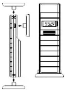
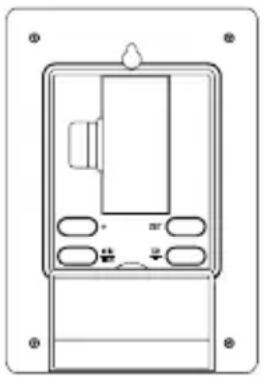
TO INSTALL AND REPLACE BATTERIES IN THE WEATHER STATION
The Weather Station uses 3 × 4 AA, IEC LR6, 1.5V batteries. To install and replace the batteries, please follow the steps below:
- Insert finger or other solid object in the space at the bottom center of the battery compartment and lift up to remove the cover.
- Insert batteries observing the correct polarity (see marking).
- Replace compartment cover.
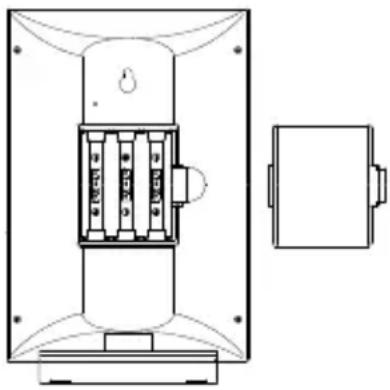
TO INSTALL AND REPLACE BATTERIES IN THE THERMOHYGRO TRANSMITTER
The Thermo-hygro transmitter uses 2 × AA , IEC, LR6, 1.5V batteries. To install and replace the batteries, please follow the steps below:
- Remove the cover.
- Insert the batteries, observing the correct polarity (see marking).
- Replace the battery cover.
Note:
In the event of changing batteries in any of the units, all units need to be reset by following the setting up procedures. This is due to a random security code assigned by the transmitter at start-up. This code must be received and stored by the Weather Station in the first 3 minutes of power being supplied to the transmitter.
BATTERY CHANGE:
It is recommended to replace the batteries in all units regularly to ensure optimum accuracy of these units (Battery life see Specifications below).

Please participate in the preservation of the environment. Return used batteries to an authorized depot.
RESETTING
The Weather Station and the Thermo-hygro transmitter need to be reset when one of the following conditions occur:
-
Unsuccessful 915MHz signal reception.
-
Malfunction on the units.
- Batteries replacement.
For resetting, remove all batteries from the units. Wait at least for 1 minute before powering up the Weather station again. Proceed from step 1 in "Setting Up".
ATOMIC TIME - WWVB RADIO CONTROLLED TIME
The NIST (National Institute of Standards and Technology—Time and Frequency Division) WWVB radio station is located in Ft. Collins, Colorado, and transmits the exact time signal continuously throughout the United States at 60kHz . The signal can be received up to 2,000 miles away through the internal antenna in the Weather Station. However, due to the nature of the Earth's Ionosphere, reception is very limited during daylight hours. The wireless weather station will search for a signal every night when reception is best.
The WWVB radio station receives the time data from the NIST Atomic clock in Boulder, Colorado. A team of atomic physicists is continually measuring every second, of every day, to an accuracy of ten billionths of a second per day. These physicists have created an international standard, measuring a second as 9,192,631,770 vibrations of a Cesium-133 atom in a vacuum. For more detail, visit http://www.boulder.nist.gov/timefreq.htm. To listen to the NIST time, call (303)499-7111. This number will connect you to an automated time, announced at the top of the minute in "Coordinated Universal Time", which is also known as Greenwich Mean Time (GMT). This time does not follow Daylight Saving Time changes. After the top of the minute, a tone will sound for every second. It is possible that your wireless weather station will not be exactly on the second due to the variance in the quartz. However, the clock will adjust the quartz timing over the course of several days to be very accurate; under 0.10 seconds per day.
FUNCTION KEYS:
Weather Station:
The Weather Station has 5 easy to use function keys, located on the right side of the weather station:

SET key
- Press and hold the key to enter manual setting modes: LCD contrast, time zone, DST ON/OFF, time reception ON/OFF, 12/24 hour display, manual time setting, calendar, temperature ^ C / ^ F , pressure hPa/inHg, relative pressure value, and weather icon sensitivity setting
- Reset all MIN/MAX records
- Stop the alarm during alarm ringing
- Stop snooze mode
Back-light on
ALM/DATE key
- Press and hold key for 3 seconds to enter the alarm setting mode
Active/de-active the alarm time - Stop the alarm during alarm ringing
- Stop snooze mode
- Display date
Back-light on
IN key
- Press to toggle between MAX/MIN and current indoortemperature/humidity data
- Press to set the alarm hour (inside alarm setting mode)
- Decrease relative pressure value (within manual set mode)
- Stop the alarm during alarm ringing
- Stop snooze mode
Back-light on
OUT/+key
- Press shortly to toggle between MAX/MIN and current outdoor temperature/humidity data
- Increase, change, toggle all values in manual set mode
- Press to set the alarm minute (inside alarm setting mode)
- Stop the alarm during alarm ringing
- Stop snooze mode
Back-light on
SNOOZE/CH key
Active snooze function during alarm ringing
- Exit the manual set mode and alarm setting mode
- Switch among display of channels (if more than 1 transmitter is used)
Back-light on
LCD SCREEN
The LCD screen is split into 4 sections displaying the information for time/calendar/alarm/moon phase, indoor data, weather forecast and outdoor data.
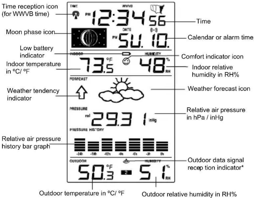
- When the signal is successfully received by the Weather Station, the outdoor transmission icon will be switched on. (If not successful, the icon will not be shown on LCD). The user can then easily see whether the last reception was successful (icon on) or not (icon off). On the other hand, the short blinking of the icon shows that a reception is currently taking place.
MANUAL SETTINGS:
The following manual settings can be changed when pressing the SET key for:
- LCD contrast setting
- Time zone setting
- DST ON/ OFF setting (daylight saving time)
Time reception ON/OFF setting
12/24-hour format setting -
Manual time setting
Calendar setting -
^ C / ^ F temperature setting
- hPa / inHg pressure setting
- Relative air pressure setting
- Weather forecasting icon sensitivity setting
LCD CONTRAST SETTING:

The LCD contrast can be set within 8 levels, from LCD 0 to LCD7 (Default setting is LCD 4):
- Press and hold the SET key until the digit starts flashing.
- Use the OUT/+ key to view all levels of contrast.
- Select the desired LCD contrast. Confirm with the SET key and enter in the Time Zone setting.
TIME ZONE SETTING:
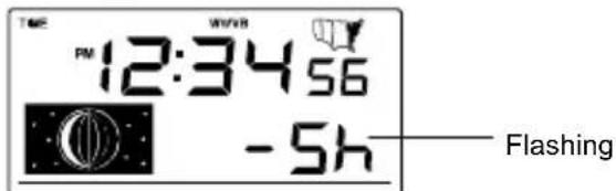
The time zone default of the Weather Station is "-5h". To set a different time zone:
- The current time zone value starts flashing.
- Use the OUT/+ key to set the time zone. The range runs from 0 to -12 and then runs from +12 back to 0 in consecutive 1-hour intervals.
- Confirm with the SET key and enter the Daylight saving time ON/OFF setting.
DAYLIGHT SAVING TIME ON/ OFF SETTING
Daylight time saving (DST) function can be set ON/OFF. Default setting "ON"

- The digit "ON" will start flashing on the LCD.
- Use the OUT/ ^+ key to turn OFF the daylight time saving function.
- Confirm with the SET key and enter the Time reception ON/OFF setting.
TIME RECEPTION ON/OFF SETTING:

In area where reception of the WWVB time is not possible, the WWVB time reception function can be turn OFF. The clock will then work as a normal Quartz clock. (Default setting is ON).
- The digit "ON" will start flashing on the LCD.
- Use the OUT/+ key to turn OFF the time reception function.
- Confirm with the SET key and enter the 12/24-hour format setting
Note:
If the Time Reception function is turn OFF manually, the clock will not attempt any reception of the WWVB time as long as the Time Reception OFF function is activated.
The time reception icon and the "WWVB" icon will not be displayed on the LCD.
12/24-HOUR FORMAT SETTING:

The hour display can be selected to show hours in 12-hour or 24-hour settings. (Default 12-Hour)
- Use the OUT/+ key to toggle between "12H" or "24H".
- Confirm with the SET key and enter the Manual time setting.
MANUAL TIME SETTING:
In case the Weather Station cannot detect the WWVB-signal (for example due to disturbances, transmitting distance, etc.), the time can be manually set. The clock will then work as a normal Quartz clock.

- The hour digit will start flashing.
-
Use the OUT/ ^+ key to set the hour.
-
Press again the SET key to set the minutes. The minute digits start flashing.
- Use the OUT/+ key to set the minutes.
- Confirm with the SET key and enter the Calendar setting.
Note:
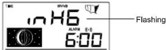
The unit will still try to receive the signal between 0:00 and 6:00 am every day despite it being manually set, if the WWVB reception function has been set ON. When it does receive the signal, it will change the manually set time into the received time. During reception attempts the WWVB tower icon will flash. If reception has been unsuccessful, then the WWVB tower icon will not appear but reception will still be attempted the following hour.
CALENDAR SETTING:

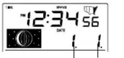
Date and month (24hr time format)
Month and date (12hr time format)
The date default of the Weather station is 1.1.2006.Once the radiocontrolled time signals are received, the date is automatically updated. However, if the signals are not received, the date can also be set manually.
- The year starts flashing.
- Use the OUT/+ key to set the year (between year 2003-2029).
- Press the SET key again to confirm and to enter the month setting. The month starts flashing.
- Use the OUT/+ key to set the month.
- Press the SET key again to confirm and to enter the date setting mode. The date starts flashing.
- Use the OUT/+ key to set the date.
- Confirm all calendar settings with the SET key and enter the Temperature unit setting.
°C/°F TEMPERATURE SETTING:
The temperature display can be selected to show temperature data in ^ C or ^ F (Default ^ F ).
-
Use the OUT/+ key to toggle between "C" or "F".
-
Confirm with the SET key and enter the Air pressure unit setting.
hPa / inHg PRESSURE UNIT SETTING:
The pressure display can be selected to show relative air pressure in hPa or inHg (default is "inHg").
- Use the OUT/+ key to toggle between "hPa" or "inHg" unit.
- Confirm with the SET key and enter the Relative air pressure value setting.
Note: Units of weather icon sensitivity and air pressure history are not affected. They are always expressed in hPa.
RELATIVE AIR PRESSURE VALUE SETTING
The default relative pressure value is 29.92 inHg (1013 hPa). This can be manually set to another value within the range of 28.35 - 30.72 inHg (960 - 1040 hPa) for a better reference.
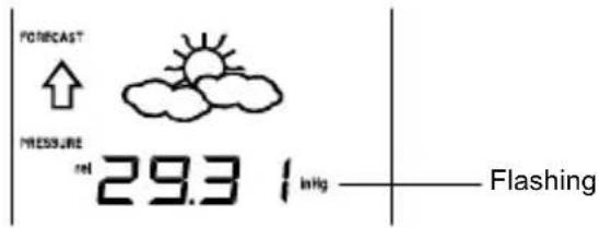
- The current relative pressure value will start flashing
- Use the OUT/+ key to increment and IN key to decrement the value.
- Keep holding the key allows the value to advance faster.
- Confirm with the SET key and enter the Weather forecast icon sensitivity setting.
WEATHER FORECASTING ICON SENSITIVITY SETTING:
For locations with rapid changes of weather conditions, the weather icons sensitivity can be set to a different level for faster display of weather conditions.

- The current sensitivity value will start flashing.
- Use the OUT/+ key to set the weather sensitivity level. There are 3 levels of setting: 2, 3 and 4. The value corresponds to the change of air pressure in hPa before the weather icon will switch to another state. Level 2 is the most sensitive setting, level 4 is the slowest recording setting (default setting is "3").
- Confirm with the SET key and exit the Manual settings.
TO EXIT THE MANUAL SETTING MODE
To exit the manual setting mode anytime during the manual setting, press the SNOOZE/CH key or wait for automatic timeout. The mode will return to normal time display.
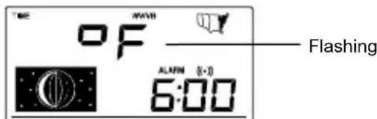
ALARM SETTING:

The alarm time can be set when pressing the ALM/DATE key.
- Press and hold the ALM/DATE key to enter the alarm set mode. The alarm digits flash.
- Use the IN key to set the alarm hour.
- Use the OUT/+ key to set the alarm minute.
- Confirm with SNOOZE/CH key and exit the Alarm setting. The icon (()) will be displayed along with the set alarm time.
Note:
If the calendar is displayed in the Weather station, the alarm is NOT active. To view and active the alarm, press the ALM/DATE key. The alarm icon and the alarm time will be displayed, indicating that the alarm setting is activated.
The maximum alarm ring duration is 2 minutes.
SNOOZE SETTING AND STOPPING THE ALARM:
10 minutes snooze function can be set when the alarm is ringing by pressing the SNOOZE/CH key.
When the alarm is snoozing, the alarm icon () will remain flashing indicating that the alarm is active but is in Snooze mode. To stop the snooze function when it is in snooze period, press any key except the SNOOZE/CH key.
To stop the alarm, press any key during alarm ringing, except the SNOOZE/CH key.
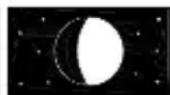
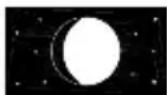
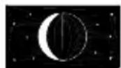
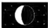
MOON PHASES SYMBOL
The Moon icon of the Weather station will also display all 12 Moon phases throughout the year according to the set calendar.
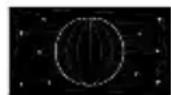
New Moon

Small Waxing Crescent

Large Waxing Crescent

First Quarter
Small Waxing Gibbous
Large Waxing Gibbous
Small Waning Crescent
Large Waning Crescent

Last Quarter
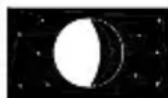
Small Waning Gibbous

Large Waning Gibbous

Full Moon
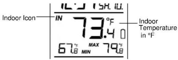
INDOOR RELATIVE HUMIDITY AND INDOOR TEMPERATURE:
The indoor temperature and humidity data, the indoor comfort indicator are automatically updated and displayed on the second section of the LCD.

THE COMFORT LEVEL INDICATOR:
Comfortable
A happy face icon " " indicating a temperature level between 20^ and 25.9^ and relative humidity reading between 45% and 65% .
Uncomfortable
: A sad face icon "®" indicating any value outside the comfortable range.
TOGGLING AND RESETTING THE INDOOR READINGS:
-
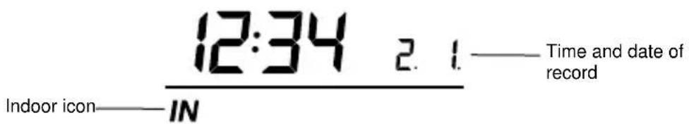
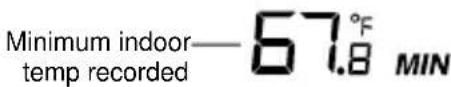
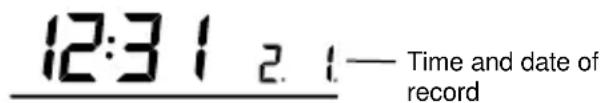
Press the IN key to toggle between the indoor current, MAX/MIN temperature and humidity data. The time and dates of the recorded data will also be displayed in the time and calendar sections (for temperature data only). Once to show the MAX indoor temperature and humidity data with the recorded time and date. Twice to show the MIN indoor temperature and humidity data with the recorded time and date. Three times to return to the current displayed values
-
Once the MIN or MAX data is displayed, press and hold the SET key for 3 seconds to reset the respective MIN or MAX record to current temperature and humidity data, and current time, date display.
Note: The MIN or MAX data needs to be reset individually.
WEATHER FORECAST AND WEATHER TENDENCY:
WEATHER FORECASTING ICONS:
Weather icons in the third section of LCD can be displayed in any of the following combinations:

Sunny
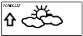
Cloudy with sunny intervals
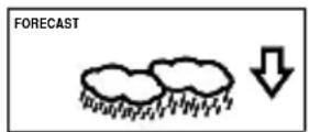
Rainy
For every sudden or significant change in the air pressure, the weather icons will update accordingly to represent the change in weather. If the icons do not change, then it means either the air pressure has not changed or the change has been too slow for the Weather station to register. However, if the icon displayed is a sun or raining cloud, there will be no change of icon if the weather gets any better (with sunny icon) or worse (with rainy icon) since the icons are already at their extremes.
The icons displayed forecasts the weather in terms of getting better or worse and not necessarily sunny or rainy as each icon indicates. For example, if the current weather is cloudy and the rainy icon is displayed, it does not mean that the product is faulty because it is not raining. It simply means that the air pressure has dropped and the weather is expected to get worse but not necessarily rainy.
Note:
After setting up, readings for weather forecasts should be disregarded for the next 12-24 hours. This will allow sufficient time for the Weather station to collect air pressure data at a constant altitude and therefore result in a more accurate forecast.
Common to weather forecasting, absolute accuracy cannot be guaranteed. The weather forecasting feature is estimated to have an accuracy level of about 75% due to the varying areas the Weather station has been designed for use. In areas that experience sudden changes in weather (for example from sunny to rain), the Weather station will be more accurate compared to use in areas where the weather is stagnant most of the time (for example mostly sunny).
If the Weather station is moved to another location significantly higher or lower than its initial standing point (for example from the ground floor to the upper floors of a house), discard the weather forecast for the next 12-24
hours. By doing this, the Weather Station will not mistake the new location as being a possible change in air-pressure when really it is due to the slight change of altitude.
WEATHER TENDENCY INDICATOR
Working together with the weather icons is the weather tendency indicators (located on the left and right sides of the weather icons). When the indicator points upwards, it means that the air-pressure is increasing and the weather is expected to improve, but when indicator points downwards, the air-pressure is dropping and the weather is expected to become worse.
Taking this into account, one can see how the weather has changed and is expected to change. For example, if the indicator is pointing downwards together with cloud and sun icons, then the last noticeable change in the weather was when it was sunny (the sun icon only). Therefore, the next change in the weather will be cloud with rain icons since the indicator is pointing downwards.
Note:
Once the weather tendency indicator has registered a change in air pressure, it will remain permanently visualized on the LCD.
AIR PRESSURE HISTORY (ELECTRONIC BAROMETER WITH BAROMETRIC PRESSURE TREND)
The third section of the LCD also shows the relative air pressure value and the air pressure history.

The bar chart indicates the air pressure history trend over the last 24 hours in 7 steps, 0h, -3h, -6h, -9h, -12h, -18h, and -24h. The "0h" represents the current full hour air pressure recording. The columns represent the "hPa" (0, ± 2, ± 4, ± 6) at specific time. The "0" in the middle of this scale is equal to the current pressure and each change (± 2, ± 4, ± 6) represents how high or low in "hPa" the past pressure was compared to the current pressure.
If the bars are rising it means that the weather is getting better due to the increase of air pressure. If the bars go down, it means the air pressure has dropped and the weather is expected to get worse from the present time "Oh".
Note:
For accurate barometric pressure trends, the Weather Station should operate at the same altitude for example, it should not be moved from the
ground to the second floor of the house. Should the unit be moved to a new location, discard readings for the next 12-24 hours.
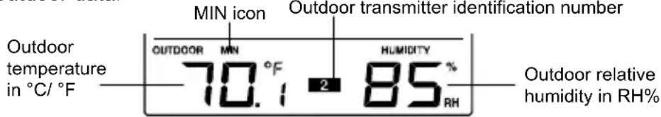
OUTDOOR TEMPERATURE/HUMIDITY DATA
The fourth LCD section shows the outdoor temperature and humidity, the reception indicator, the transmitter identification number and the MIN/MAX outdoor data.
TOGGLING AND RESETTING THE OUTDOOR DATA
- To toggle between the outdoor current, MAX/MIN temperature and humidity data and the times (for temperature data only) they were recorded press the OUT/+ key:
Once to show the MAX outdoor temperature and humidity data with the recorded time and date.
Twice to show the MIN outdoor temperature and humidity data with the recorded time and date.
Three times to return to the current displayed values.
- Once the MIN or MAX data is displayed, press and hold the SET key for 3 seconds to reset the respective MIN or MAX record to current temperature and humidity data, and current time, date display.
Note: The MIN or MAX data needs to be reset individually.
TO VIEW THE MIN/MAX DATA FROM DIFFERENT TRANSMITTERS
When more than 1 transmitter used:
- To toggle between transmitters, press the SNOOZE/CH key:
Once to show transmitter 2
Twice to show transmitter 3
Three times to return to transmitter 1
-
Use OUT/ ^+ key to view the MIN/MAX temperature and humidity data for the selected transmitter.
-
To reset the minimum and maximum temperature and humidity data, and the times at which they were recorded, press the SET key continuously for about 3 seconds. This will reset the MIN/MAX data recorded to the current time, date, temperature and humidity. The current time taken is the normal displayed time and does not regard the time zone set for the unit.
Note: the MIN/MAX data for each transmitter needs to be reset separately.
BACK-LIGHT
The back-light is automatically switched ON when any keys are pressed. The back-light will be switched on for approximately 8 seconds before automatically switching OFF.
LOW BATTERY INDICATOR
Low battery indicator is displayed on the LCD when the batteries require changing.
ABOUT THE OUTDOOR TRANSMITTER
The range of the Thermo-hygro transmitter may be affected by the temperature. At cold temperatures the transmitting distance may be decreased. Please bear this in mind when positioning the transmitters. Also the batteries may be reduced in power for the Thermo-hygro transmitter.
CHECKING FOR 915MHz RECEPTION
If the outdoor temperature and humidity data are not being received within three minutes after setting up (or outdoor display always show "--. -" in the outdoor section of the Weather station during normal operation), please check the following points:
- The distance of the Weather station or transmitters should be at least 6 feet (2 meters) away from any interfering sources such as computer monitors or TV sets.
- Avoid placing the transmitters onto or in the immediate proximity of metal window frames.
- Using other electrical products such as headphones or speakers operating on the 915MHz-signal frequency may prevent correct signal transmission or reception. Neighbors using electrical devices operating on the 915MHz-signal frequency can also cause interference
Note:
When the 915MHz signal is received correctly, do not re-open the battery cover of either the transmitter or Weather station, as the batteries may spring free from the contacts and force a false reset. Should this happen accidentally then reset all units (see "Setting up" above) otherwise transmission problems may occur.
The transmission range is around 330 feet (100 meters) from the Thermo-hygro transmitter to the Weather station (in open space). However, this depends on the surrounding environment and interference levels. If no reception is possible despite the observation of these factors, all system units have to be reset (see "Setting up" above).
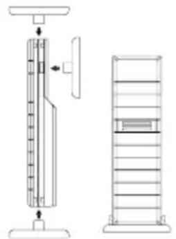
POSITIONING THE WEATHER STATION:
The weather station has been designed to be hang on a wall or free standing.
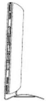
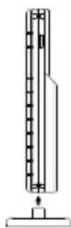
For free standing:
Simply attached the stand to the bottom of the unit and place onto a flat surface.
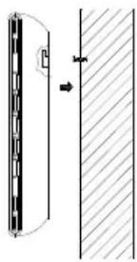
To wall mount
Choose a sheltered place. Avoid direct rain and sunshine.
Before wall mounting, please check that the outdoor temperature and humidity values can be received from the desired locations. To wall mount:
- Fix a screw (not supplied) into the desired wall, leaving the head extended out the by about 0.2" (5mm).
- Hang it onto the screw. Remember to ensure that it locks into place before releasing.
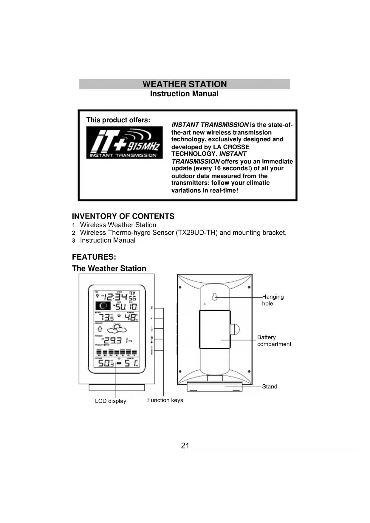
POSITIONING THE THERMO-HYGRO TRANSMITTER

The thermo-hygro transmitter is supplied with a holder that may be attached to a wall with the two screws supplied. The sensor can also be position on a flat surface by securing the stand to the bottom to the sensor.
To wall mount:

- Secure the bracket onto a desired wall using the screws and plastic anchors.
- Clip the sensor onto the bracket.
Note:
Before permanently fixing the sensor wall base, place all units in the desired locations to check that the outdoor
temperature and humidity readings are receivable. In event that the signal is not received, relocate the sensor(s) or move them slightly as this may help the signal reception.
CARE AND MAINTENANCE:
- Extreme temperatures, vibration and shock should be avoided as these may cause damage to the unit and give inaccurate forecasts and readings.
- Precautions shall be taken when handling the batteries. Injuries, burns, or property damage may be resulted if the batteries are in contact with conducting materials, heat, corrosive materials or explosives. The batteries shall be taken out from the unit before the product is to be stored for a long period of time.
- Immediately remove all low powered batteries to avoid leakage and damage. Replace only with new batteries of the recommended type.
- When cleaning the display and casings, use a soft damp cloth only. Do not use solvents or scouring agents as they may mark the LCD and casings.
- Do not submerge the unit in water.
Special care shall be taken when handling a damaged LCD display. The liquid crystals can be harmful to user's health. - Do not make any repair attempts to the unit. Return them to their original point of purchase for repair by a qualified engineer. Opening and tampering with the unit may invalidate their guarantee.
- Never touch the exposed electronic circuit of the device as there is a danger of electric shock should it become exposed.
- Do not expose the units to extreme and sudden temperature changes, this may lead to rapid changes in forecasts and readings and thereby reduce their accuracy.
SPECIFICATIONS:
Temperature measuring range:
Indoor : 14.2^ to 139.8^ with 0.2^ resolution
-9.9°C to +59.9°C with 0.1°C resolution
(“OF.L” displayed if outside this range)
Outdoor : -39.8°F to +139.8°F with 0.2°F resolution
-39.9°C to +59.9°C with 0.1°C resolution
(“OF.L” displayed if outside this range)
Indoor humidity range : 1% to 99% with 1% resolution
(Display“- - if temperature is OL.F; display“- - if < 1% and “99%” if > 99%)
Outdoor humidity range : 1% to 99% with 1% resolution
(Display “- - ” if outside temperature is OF.L; display 1% if < 1% and 99% if >99% )
Interior data checking intervals
Indoor Temperature : Every 15 seconds
Humidity : Every 20 seconds
Air pressure checking interval : Every 15 seconds
Outdoor temperature and humidity data checking interval:
Every 4 seconds (or every 15 minutes if data are lost and display "---")
Transmission range : up to 330 feet /100 meters (open space)
Power consumption: (alkaline batteries recommended)
Weather station : 3 × AA , IEC LR6, 1.5V
Thermo-hygro transmitter : 2 x AA, IEC LR6, 1.5V
Battery life : up to 24 months
Dimensions (L x W x H):
Weather station : 6.88” x 4.72” x 1.22” / 175 x 120 x 31 mm
Thermo-hygro transmitter : 1.50" x 0.83" x 5.05"/ 38.2 x 21.2 x 128.3mm
LIABILITY DISCLAIMER
- The electrical and electronic wastes contain hazardous substances. Disposal of electronic waste in wild country and/or in unauthorized grounds strongly damages the environment
- Please contact your local or/and regional authorities to retrieve the addresses of legal dumping grounds with selective collection
- All electronic instruments must from now on be recycled. User shall take an active part in the reuse, recycling and recovery of the electrical and electronic waste.
- The unrestricted disposal of electronic waste may do harm on public health and the quality of environment.
- This product must however not be thrown in general rubbish collection points.
- As stated on the gift box and labeled on the product, reading the "User manual" is highly recommended for the benefit of the user.
- The manufacturer and supplier cannot accept any responsibility for any incorrect readings and any consequences that occur should an inaccurate reading take place.
- This product is not to be used for medical purposes or for public information.
- This product is only designed to be used in the home as indication of the future weather and is not 100% accurate. Weather forecasts given by this product should be taken only as an indication and not as being totally accurate.
The specifications of this product may change without prior notice. - This product is not a toy. Keep out of the reach of children.
- No part of this manual may be reproduced without written consent of the manufacturer.
WARRANTY
La Crosse Technology, Ltd provides a 1-year limited warranty on this product against manufacturing defects in materials and workmanship.
This limited warranty begins on the original date of purchase, is valid only on products purchased and used in North America and only to the original purchaser of this product. To receive warranty service, the purchaser must contact La Crosse Technology, Ltd for problem determination and service procedures. Warranty service can only be performed by a La Crosse Technology, Ltd authorized service center. The original dated bill of sale must be presented upon request as proof of purchase to La Crosse Technology, Ltd or La Crosse Technology, Ltd's authorized service center.
La Crosse Technology, Ltd will repair or replace this product, at our option and at no charge as stipulated herein, with new or reconditioned parts or products if found to be defective during the limited warranty period specified above. All replaced parts and products become the property of La Crosse Technology, Ltd and must be returned to La Crosse Technology, Ltd.
Replacement parts and products assume the remaining original warranty, or ninety (90) days, whichever is longer. La Crosse Technology, Ltd will pay all expenses for labor and materials for all repairs covered by this warranty. If necessary repairs are not covered by this warranty, or if a product is examined which is not in need or repair, you will be charged for the repairs or examination.
The owner must pay any shipping charges incurred in getting your La Crosse Technology, Ltd product to a La Crosse Technology, Ltd authorized service center.
Your La Crosse Technology, Ltd warranty covers all defects in material and workmanship with the following specified exceptions: (1) damage caused by accident, unreasonable use or neglect (including the lack of reasonable and necessary maintenance); (2) damage occurring during shipment (claims must be presented to the carrier); (3) damage to, or deterioration of, any accessory or decorative surface; (4) damage resulting from failure to follow instructions contained in your owner's manual; (5) damage resulting from the performance of repairs or alterations by someone other than an authorized La Crosse Technology, Ltd authorized service center; (6) units used for other than home use (7) applications and uses that this product was not intended or (8) the products inability to receive a signal due to any source of interference.
This warranty covers only actual defects within the product itself, and does not cover the cost of installation or removal from a fixed installation, normal
set-up or adjustments, claims based on misrepresentation by the seller or performance variations resulting from installation-related circumstances.
LA CROSSE TECHNOLOGY, LTD WILL NOT ASSUME LIABILITY FOR INCIDENTAL, CONSEQUENTIAL, PUNITIVE, OR OTHER SIMILAR DAMAGES ASSOCIATED WITH THE OPERATION OR MALFUNCTION OF THIS PRODUCT. THIS PRODUCT IS NOT TO BE USED FOR MEDICAL PURPOSES OR FOR PUBLIC INFORMATION. THIS PRODUCT IS NOT A TOY. KEEP OUT OF CHILDREN'S REACH.
This warranty gives you specific legal rights. You may also have other rights specific to your State. Some States do no allow the exclusion of consequential or incidental damages therefore the above exclusion of limitation may not apply to you.
For warranty work, technical support, or information contact:
La Crosse Technology, Ltd
2809 Losey Blvd. S.
La Crosse, WI 54601
Phone: 608.782.1610
Fax: 608.796.1020
e-mail:
support@lacrossetechnology.com
(warranty work)
sales@lacrossetechnology.com
(information on other products)
web:
www.lacrossetechnology.com
Question? Instructions?
Please visit: www.lacrossetechnology.com/9037
All rights reserved. This handbook must not be reproduced in any form, even in excerpts, or duplicated or processed using electronic, mechanical or chemical procedures without written permission of the publisher.
This handbook may contain mistakes and printing errors. The information in this handbook is regularly checked and corrections made in the next issue. We accept no liability for technical mistakes or printing errors, or their consequences. All trademarks and patents are acknowledged.
WS-9080U-IT
915 MHz WIRELESS TEMPERATURE STATION
Instruction manual


Tomorrow's Weather Today
Contents
Language
Page
E
n
g
1
i
s
French
41
s
p
a
n
i
s
h
TABLE OF CONTENTS
| Topic | Page |
| Inventory of Contents 3 | |
| Features | 4 |
| Setting Up 6 | |
| Battery Installation 10 | |
| Function Keys 12 | |
| LCD Screen and Settings 14 | |
| Atomic Time -WWVB Radio Controlled Time 16 | |
| Manual Settings 17 | |
| Display of Indoor Temperature Reading 25 | |
| Display of Outdoor Temperature Reading 26 | |
| Display of Indoor Minimum and Maximum records 26 | |
| Display of Outdoor Minimum and Maximum records 28 | |
| Daily Indoor Minimum and Maximum Temperature display 29 | |
| Daily Outdoor Minimum and Maximum Temperature display 30 | |
| 915 MHz Reception 31 | |
| Mounting | 32 |
| Care and Maintenance 34 | |
| Specifications | 35 |
| Warranty | 36 |
This product offers:

INSTANT TRANSMISSION is the state-of-the-art new wireless transmission technology, exclusively designed and developed by LA CROSSE TECHNOLOGY. INSTANT TRANSMISSION offers you an immediate update (every 4 seconds!) of all your outdoor data measured from the sensors: follow you climatic variations in real-time!
INVENTORY OF CONTENTS
- Wireless Temperature Station
- Wireless Temperature Sensor (TX29U) and mounting bracket.
- Instruction Manual and Warranty Card.
FEATURES:
The Temperature Station


Atomic Time function (WWVB Radio controlled time) or manual time setting options
- Atomic Time reception On/Off
Daylight Saving Time ON/OFF
12/24 hour display
- Hour and minute display
Calendar display
Time zone option ± 12 hours
- Wireless transmission at 915 MHz
- Outdoor signal reception intervals at 4-second
Temperature display in degrees Fahrenheit (^) or Celsius (^) selectable
- Indoor and Outdoor temperature display with MIN/MAX recording (records can be reset)
- Can receive up to 3 outdoor sensors
- Daily minimum and maximum indoor temperature display
- Daily minimum and maximum outdoor temperature display
- Low battery indicator
LCD contrast adjustable
Table standing/ Wall mounting
The Outdoor Temperature Sensor
- Remote transmission of outdoor temperature to Temperature Station by 915 MHz
Water-resistant casing - Wall mounting case (Mount in a sheltered place. Avoid direct rain and sunshine)
SETTING UP:
When one Sensor is used
-
First, insert the batteries into the temperature sensor. (see "Install and replace batteries in the temperature sensor").
-
Immediately after and within 30 seconds, insert the batteries into Temperature Station (see "Install and replace batteries in the Temperature Station"). Once the batteries are in place, all segments of the LCD will light up briefly. Following the
time as 12:00 and the indoor temperature will be displayed. If these are not displayed after 60 seconds, remove the batteries and wait for at least 10 seconds before reinserting them.
- After inserting the batteries into the sensor, the Temperature Station will start receiving data from the sensor. The outdoor temperature and the signal reception icon should then be displayed on the Temperature Station. If this does not happen after 5 minutes, the batteries will need to be removed from both units and reset from step 1.
- In order to ensure sufficient 915 MHz transmission however, there should be no more than 330 feet (100 meters) between the final position of the Temperature Station and the sensor (see notes on "Mounting" and "915 MHz Reception").
- Once the remote temperature has been received and displayed on the Temperature Station, the WWVB time code reception is automatically started. This takes typically between 3-5 minutes in good conditions—but may take up to 4 nights.
When more than one sensor is to be used
- User shall remove all the batteries from the Temperature Station and sensors and wait 60 seconds if setting has been done with one sensor before.
- Insert the batteries to the first sensor.
- Within 30 seconds of powering up the first sensor, insert the batteries into to the Temperature Station. Once the batteries are in place, all segments of the LCD will
light up briefly. Following time as 12:00 and the indoor temperature will be displayed. If they are not shown in LCD after 60 seconds, remove the batteries and wait for at least 60 seconds before reinserting them.
- The outdoor temperature from the first sensor (channel 1) should then be displayed on the Temperature Station. Also, the signal reception icon will be displayed. If this does not happen after 2 minutes, the batteries will need to be removed from both units and reset from step 1.
- Insert the battery into the second sensor immediately after (within 10 seconds after) the reading form the first sensor is shown on LCD.
- The outdoor temperature from the second sensor and the "channel 2" icon should then be displayed on the Temperature Station. If this does not happen after 2 minute, the batteries will need to be removed from all the units and reset from step 1.
- Insert the batteries into the third sensor immediately after (within 10 seconds after) the reading from the second sensor is shown on LCD.
- Then within 2 minutes, the channel 3 outdoor data from the third sensor will be displayed and the channel icon will shift back to "1" once the third sensor is successfully received. If this is not happen, user shall restart the setting up from step 1.
- In order to ensure sufficient 915 MHz transmission there should be a distance of no more than 330 feet (100 meters) between the final position of the Temperature Station and the sensor (see notes on "Mounting" and "915 MHz Reception").
Note:
Transmission problems will arise if the setting for additional sensors is not followed as described above. Should transmission problems occur, it is necessary to remove the batteries from all units and follow the set-up from step 1.
If the signal reception is not successful on the first frequency (915MHz) for 45 seconds, the frequency is changed to 920MHz and the learning is tried for another 45 seconds. If still not successful the reception is tried for 45 seconds on 910MHz. This will also be done for re-synchronization.
- Once the remote temperature has been received and displayed on the Temperature Station, the WWVB time code reception is automatically started. This takes typically between 3-5 minutes in good conditions.
IMPORTANT:
Transmission problems will arise if the setting for additional sensors is not followed as described above. Should transmission problems occur, it is necessary to remove the batteries from all units and follow the set-up from step 1.
If after 10 minutes, the Atomic auto-set time (WWVB time) has not been received, press the SET key to manually enter a time initially.
Daily WWVB reception is attempted at full hour between 12:00 am to 6:00 am. If the
reception is successful, there will no reception attempt until the following day. When this is successful, the received time will override the manually set time. The date is also updated with the received time. (Please refer also to notes on "Atomic auto-set time - WWVB Radio controlled Time" and "Manual Time Setting").
BATTERY INSTALLATION
INSTALL AND REPLACE BATTERIES IN THE TEMPERATURE STATION
The Temperature Station uses 2 x AAA, IEC LR3, 1.5V batteries. To install and replace the batteries, please follow the steps below:
- Remove the cover at the back of the Temperature Station.
- Insert batteries observing the correct polarity (see marking).
- Replace compartment cover.
INSTALL AND REPLACE BATTERIES IN THE TEMPERATURE SENSOR

The temperature sensor uses 2 × AA , IEC LR6, 1.5V battery. To install and replace the batteries, please follow the steps below:
- Remove the battery compartment cover.
- Insert the batteries, observing the correct polarity (see marking).
- Replace the battery cover on the unit.
Note:
In the event of changing batteries in any of the units, all units need to be reset by following the setting up procedures. This is because a random security code is assigned by the sensor at start-up and this code must be received and stored by the Temperature Station in the first 3 minutes of power being supplied to it
BATTERY CHANGE:
It is recommended to replace the batteries in all units regularly to ensure optimum accuracy of these units (Battery life see Specifications below).

Please participate in the preservation of the environment. Return used batteries to an authorized depot.
FUNCTION KEYS:
Temperature Station:
The Temperature Station has four easy to use function keys.
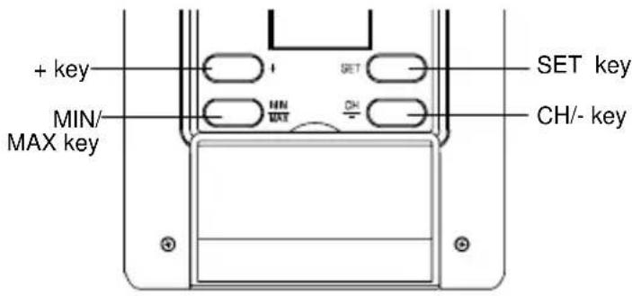
SET key (Manual Setting):
- Press and hold to enter the setting mode for the following settings: LCD contrast, Time zone, Daylight saving time ON/OFF, Atomic Time Reception (RCC) ON/OFF, 12/24 hr format, Manual time, Year, Month, Day and ^ C / ^ F settings.
MIN/ MAX key
To toggle between the minimum/ maximum indoor and outdoor temperature records
- Press to exit the setting mode
- Press to reset the minimum and maximum or temperature records of the indoor and the outdoor channel (will reset all records to current level)
+key
To make a "positive" adjustment for various settings
In normal display, press to toggle between the display of the calendar data and second of time in the time display of LCD
CH/-key
To make a "negative" adjustment for various settings
- To toggle between different outdoor channel display (when more than 1 outdoor sensor is adopted)
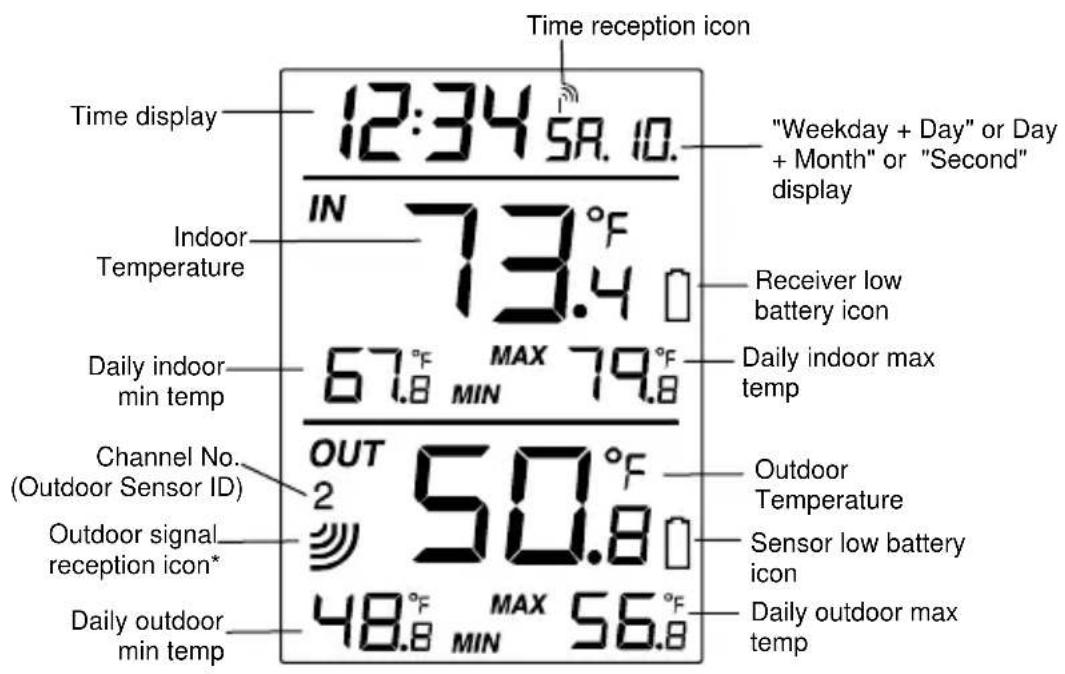
LCD SCREEN AND SETTINGS:
*When the outdoor signal is successfully received by the temperature station, this icon will be switched on. (If not successful, the icon will not be shown in LCD) So user can easily see whether the last reception was successful (icon on) or not (icon off). On the other hand, the short blinking of the icon shows that a reception is currently taking place.
Note:
The Channel No. (Outdoor Sensor No.) will be shown when more than one outdoor sensor is adopted.
For better distinctness the LCD screen is split into 3 sections displaying the information for time and date, Indoor data and outdoor data.
Section 1 - TIME AND CALENDAR
In normal mode, display the time and "weekday + day". Press the + key once to display the "day + month"; twice to display the second of time.
A signal reception symbol is shown indicating that Atomic auto-set time (WWVB time) signal is received.
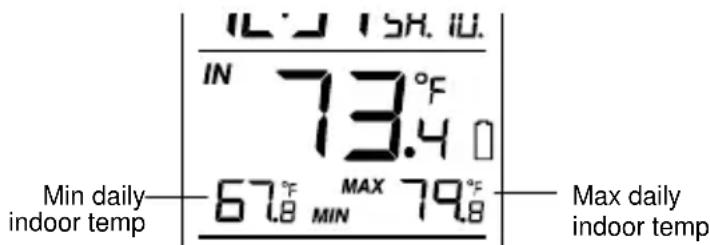
Section 2 - INDOOR TEMPERATURE
- Display current indoor temperature
- Display daily minimum and maximum indoor temperature
Section 3 - OUTDOOR TEMPERATURE
- Display current outdoor temp
- Display daily maximum and minimum outdoor temperature
ATOMIC TIME - WWVB RADIO CONTROLLED TIME
The NIST (National Institute of Standards and Technology—Time and Frequency Division) WWVB radio station is located in Ft. Collins, Colorado, and transmits the exact time signal continuously throughout the United States at 60kHz . The signal can be received up to 2,000 miles away through the internal antenna in the Temperature Station. However, due to the nature of the Earth's Ionosphere, reception is very limited during daylight hours. The wireless weather station will search for a signal every night when reception is best.
The WWVB radio station receives the time data from the NIST Atomic clock in Boulder, Colorado. A team of atomic physicists is continually measuring every second, of every day, to an accuracy of ten billionths of a second per day. These physicists have created an international standard, measuring a second as 9,192,631,770 vibrations of a Cesium-133 atom in a vacuum. For more detail, visit http://www.boulder.nist.gov/timefreq.htm. To listen to the NIST time, call (303)499-7111. This number will connect you to an automated time, announced at the top of the minute in "Coordinated Universal Time", which is also known as Greenwich Mean Time (GMT). This time does not follow Daylight Saving Time changes. After the top of the minute, a tone will sound for every second. It is possible that your
Wireless Temperature Station may not be exactly on the second due to the variance in the quartz. However, the clock will adjust the quartz timing over the course of several days to be very accurate; under 0.10 seconds per day.
MANUAL SETTINGS:
The following manual settings can be done in the setting mode:
- LCD Contrast setting
Time zone setting
Daylight Saving Time ON/OFF setting (DST) - Atomic Time reception ON/OFF setting (RCC)
12/24 hour time format setting - Manual time setting
Calendar setting (Year, Month, Date) - ^ F/^ C temperature unit setting
Press and hold the SET key for about 3 seconds to advance to the setting mode:
LCD CONTRAST SETTING

The LCD contrast can be set to 8 different levels (0 to 7) to suit the user's needs (default LCD contrast setting is LCD 4). To set the desired contrast level:
- The above display will be seen. Press the + key or CH/- key to select the level of contrast desired.
- Press the SET key to confirm and enter the "Time Zone setting" or exit the setting mode by pressing the MIN/MAX key
TIME ZONE SETTING:

The time zone default of the Temperature Station is -5 hr. To change to another time zone:
- Using the + key or CH/ key, set the time zone. The range runs between -12 to +12 hour.
- Press the SET key to confirm and enter the "Daylight Saving time ON/OFF setting" or exit the setting mode by pressing the MIN/MAX key.
DAYLIGHT SAVING TIME ON/OFF SETTING
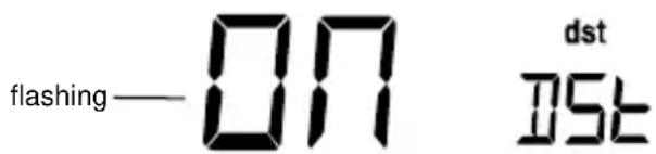
- The digit "ON DST" will start flashing on the LCD.
- Use the ^+ key or CH/-key to turn On or OFF the daylight saving time function.
- Confirm with the SET key and enter the "Time reception On/Off setting" or exit the setting mode by pressing the MIN/MAX key.
TIME RECEPTION ON/OFF SETTING

In area where reception of the WWVB time is not possible, the time reception function can be turned OFF. The clock will then work as a normal Quartz clock. (Default setting is ON).
- The digit "ON" and the time reception icon will start flashing on the LCD.
- Use the ^+ key or CH/-key to turn OFF the time reception function.
- Confirm with the SET key and enter the "12/24-Hour Display setting" or exit the setting mode by pressing the MIN/MAX key.
Note:
If the Time Reception function is turned OFF manually, the clock will not attempt any reception of the WWVB time as long as the Time Reception OFF function is activated. The Time Reception icon will not be displayed on the LCD.
12/24 HOUR TIME DISPLAY SETTING

— flashing
- After setting time reception ON/OFF, press the SET key, "12 h" or "24 h" flashes in the LCD. (default 12 h)
- Press the + key or CH/ to select the "12 h" or "24 h" display mode.
- Press the SET again to confirm and to enter the "Manual Time setting" or exit the setting mode by pressing the MIN/MAX key.
Note: When 24 h mode display is selected, the calendar format will be "date and month" display. When 12 h mode display is selected, the calendar format will be "month and date" display.
MANUAL TIME SETTING
In case the Temperature Station is not able to detect the Atomic time (WWVB) signal (disturbances, transmitting distance, etc.), the time can be manually set. The clock will then work as a normal Quartz clock.
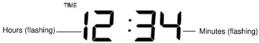
To set the clock:
- The hour digits start flashing in the time display section.
- Use the + key or CH/- key to adjust the hours and then press SET key to go to the minute setting.
- The minute will be flashing. Press the ^+ key or CH/- key to just the minutes.
- Confirm with the SET key and enter the "Calendar Setting" or exit the setting mode by pressing the MIN/MAX key
CALENDAR SETTING


"Date. Month." (for 24h time display) "Month. Date." (for 12h time display)


The date default of the temperature station is 1. 1. of the year 2006 after initial set-up. Once the radio-controlled time signals are received, the date is automatically updated. However, if the signals are not received, the date can also be set manually. To do this:
-
The year is flashing. Using the + key or CH/ key, set the year required. The range runs from 2006 to 2029 (default is 2006).
-
Press the SET key to enter the month setting mode.
- The month digit will be flashing. Press the + key or CH/ key to set the month and then press the SET key to go to the day setting.
- The day digit will be flashing. Press the + key or CH/- key to set the day.
- Confirm with SET key and enter the "oF/oC TEMPERATURE UNIT SETTING" or exit the setting mode by pressing the MIN/MAX key.
Note: The weekday of calendar will be automatically set after the month and day value is input.
^ / C TEMPERATURE UNIT SETTING

The default temperature reading is set to ^ F (degree Fahrenheit). To select ^ C (degree Celsius):
-
The "°F/ °C" will be flashing, use the + key or CH/- key to toggle between "°F" and "°C".
-
Once the desired temperature unit has been chosen, confirm with the SET key to exit the setting mode.
DISPLAY OF INDOOR TEMPERATURE READING:
The indoor temperature is measured and displayed on the second section of the LCD.
DISPLAY OF OUTDOOR TEMPERATURE READING:
The bottom LCD section shows the outdoor temperature.

DISPLAY OF INDOOR MINIMUM AND MAXIMUM RECORDS:
- In normal display mode, press the MIN/MAX key once, the minimum indoor temperature will be shown in LCD. Also the time and date of recording this temperature will be displayed.
- Then press the MIN/MAX button one more time, the maximum indoor temperature will be shown in LCD. Also the time and date of recording this temperature will be displayed.
- Press three more time the MIN/ MAX button to go back to the normal display.
DISPLAY OF OUTDOOR MINIMUM AND MAXIMUM RECORDS:
- In normal display mode, Press the MIN/MAX button three times, the outdoor minimum temperature and the time and date of recording this temperature will be displayed.
- Press the MIN/MAX button once more, the outdoor maximum temperature and the time and date of recording this temperature will be displayed.


RESETTING THE INDOOR AND OUTDOOR MINIMUM /MAXIMUM RECORDS
- In normal display mode, press the MIN/MAX button once to advance to the indoor MIN temp display.
- Press and hold the MIN/MAX key for about 3 seconds, this will reset the currently shown indoor and outdoor minimum and maximum data to the current time, date and temperature.
- Then press the MIN/MAX button three more times to return to the normal display.
Note:
The indoor minimum and maximum record, as well as the minimum and maximum records of all outdoor channels, will be reset at the same time.
DAILY INDOOR MIN AND MAX TEMPERATURE DISPLAY
This temperature station shows the daily minimum and maximum indoor temperature in normal display.
Note:
The daily minimum temperature record is reset automatically at 8:00 pm and the daily maximum temperature is reset automatically at 8:00 am every day.
DAILY OUTDOOR MIN AND MAX TEMPERATURE DISPLAY
This temperature station also displays the daily minimum and maximum outdoor temperature for each outdoor channel in normal display.
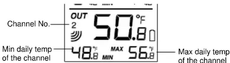
To view the daily MIN and MAX temperature of another channel, user shall press the CH key to shift to various channel display.
Note:
The daily minimum temperature record is reset automatically at 8:00 pm and the daily
maximum temperature is reset automatically at 8:00 am every day.
915 MHz RECEPTION
The Temperature Station should receive the temperature data within 5 minutes after set-up. If the temperature data is not received 5 minutes after setting up (not successfully continuously, the outdoor display shows "---"), please check the following points:
- The distance of the Temperature Station or sensor should be at least 5 to 6.5 feet (1.5 to 2 meters) away from any interfering sources such as computer monitors or TV sets.
- Avoid positioning the Temperature Station onto or in the immediate proximity of metal window frames.
- Using other electrical products such as headphones or speakers operating on the same signal frequency (915MHz) may prevent correct signal transmission and reception.
- Neighbors using electrical devices operating on the 915MHz signal frequency can also cause interference.
Note:
When the 915MHz signal is received correctly, do not re-open the battery cover of either the sensor or Temperature Station, as the batteries may spring free from the contacts and force a false reset. Should this happen accidentally then reset all units (see Setting up
above) otherwise transmission problems may occur.
The transmission range is about 330 feet (100 m) from the sensor to the Temperature Station (in open space). However, this depends on the surrounding environment and interference levels. If no reception is possible despite the observation of these factors, all system units have to be reset (see Setting up).
MOUNTING
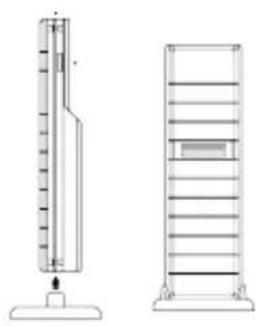
POSITIONING THE TEMPERATURE STATION:
The Temperature Station has been designed to be hung onto wall or free standing.
To wall mount
Choose a sheltered place. Avoid direct rain and sunshine. Before wall mounting, please check that the outdoor temperature values can be received from the desired locations.
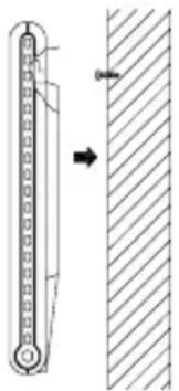
- Fix a screw (not supplied) into the desired wall, leaving the head extended out the by about 5mm.
- Remove the stand from the Temperature Station by pulling it away from the base and hang the station onto the screw. Remember to ensure that it locks into place before releasing.
Free standing
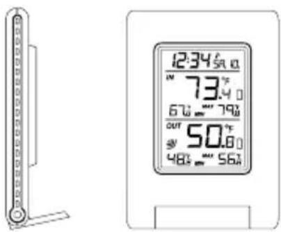
With the stand, the Temperature Station can be placed onto any flat surface.
POSITIONING THE TEMPERATURE SENSOR:
The sensor is supplied with a holder that may be attached to a wall with the two screws supplied. The sensor can also be position on a flat surface by securing the stand to the bottom to the sensor.
To wall mount:

- Secure the bracket onto a desired wall using the screws and plastic anchors.
- Clip the sensor onto the bracket.
Note:
Before permanently fixing the sensor wall base, place all units in the desired locations to check that the outdoor temperature reading is receivable. In event that the signal is not received, relocate the sensors or move them slightly as this may help the signal reception.
CARE AND MAINTENANCE:
Extreme temperatures, vibration and shock should be avoided as these may cause damage to the unit and give inaccurate forecasts and readings.
- When cleaning the display and casings, use a soft damp cloth only. Do not use solvents or scouring agents as they may mark the LCD and casings.
- Do not submerge the unit in water.
- Immediately remove all low powered batteries to avoid leakage and damage. Replace only with new batteries of the recommended type.
- Do not make any repair attempts to the unit. Return them to their original point of purchase for repair by a qualified engineer. Opening and tampering with the unit may invalidate their guarantee.
- Do not expose the units to extreme and sudden temperature changes, this may lead to rapid changes in forecasts and readings and thereby reduce their accuracy.
SPECIFICATIONS:
Temperature measuring range:
Indoor: 32^ F to +139.8^ F with 0.2^ F resolution ( 0^ C to +59.9^ C with 0.1^ C resolution, "OF.L" displayed if outside this range)
Outdoor : -39.8°F to +157.8°F with 0.2°F resolution (-39.9°C to +69.9°C with 0.1°C resolution, “OF.L” displayed if outside this range)
Indoor temperature checking interval : every 15 seconds
Outdoor data reception : approximately every 4 seconds
Power supply:
Temperature Station : 2 x AAA, IEC, LR3, 1.5V
Temperature Sensor : 2 x AA, IEC, LR6 1.5V
Battery life (Alkaline batteries recommended)
Temperature Station : Approximately 12 months
Temperature Sensor : Approximately 24 months
La Crosse Technology, Ltd provides a 1-year limited warranty on this product against manufacturing defects in materials and workmanship.
This limited warranty begins on the original date of purchase, is valid only on products purchased and used in North America and only to the original purchaser of this product. To receive warranty service, the purchaser must contact La Crosse Technology, Ltd for problem determination and service procedures. Warranty service can only be performed by a La Crosse Technology, Ltd authorized service center. The original dated bill of sale must be presented upon request as proof of purchase to La Crosse Technology, Ltd or La Crosse Technology, Ltd's authorized service center.
La Crosse Technology, Ltd will repair or replace this product, at our option and at no charge as stipulated herein, with new or reconditioned parts or products if found to be defective during the limited warranty period specified above. All replaced parts and products become the property of La Crosse Technology, Ltd and must be returned to La Crosse Technology, Ltd. Replacement parts and products assume the remaining original warranty, or ninety (90) days, whichever is longer. La Crosse Technology, Ltd will pay all expenses for labor and materials for all repairs covered by this warranty. If necessary repairs are not covered by this warranty, or if a product is examined which is not in need or repair, you will be charged for the repairs or examination. The owner must pay any shipping charges incurred in getting your La Crosse Technology, Ltd product to a La Crosse Technology, Ltd authorized service center. La Crosse Technology, Ltd will pay ground return shipping charges to the owner of the product to a USA address only.
Your La Crosse Technology, Ltd warranty covers all defects in material and workmanship with the following specified exceptions: (1) damage caused by accident, unreasonable use or neglect (including the lack of reasonable and necessary maintenance); (2) damage occurring during shipment (claims must be presented to the carrier); (3) damage to, or deterioration of, any accessory or decorative surface; (4) damage resulting from failure to follow instructions contained in your owner's manual; (5) damage resulting from the performance of repairs or alterations by someone other than an authorized La Crosse Technology, Ltd authorized service center; (6) units used for other than home use (7)
applications and uses that this product was not intended or (8) the products inability to receive a signal due to any source of interference.. This warranty covers only actual defects within the product itself, and does not cover the cost of installation or removal from a fixed installation, normal set-up or adjustments, claims based on misrepresentation by the seller or performance variations resulting from installation-related circumstances.
LA CROSSE TECHNOLOGY, LTD WILL NOT ASSUME LIABILITY FOR INCIDENTAL, CONSEQUENTIAL, PUNITIVE, OR OTHER SIMILAR DAMAGES ASSOCIATED WITH THE OPERATION OR MALFUNCTION OF THIS PRODUCT. THIS PRODUCT IS NOT TO BE USED FOR MEDICAL PURPOSES OR FOR PUBLIC INFORMATION. THIS PRODUCT IS NOT A TOY. KEEP OUT OF CHILDREN'S REACH.
This warranty gives you specific legal rights. You may also have other rights specific to your State. Some States do no allow the exclusion of consequential or incidental damages therefore the above exclusion of limitation may not apply to you.
For warranty work, technical support, or information contact:
La Crosse Technology, Ltd
2809 Losey Blvd. S.
La Crosse, WI 54601
Phone: 608.782.1610
Fax: 608.796.1020
e-mail:
support@lacrossetechnology.com
(warranty work)
sales@lacrossetechnology.com
(information on other products)
web:
www.lacrossetechnology.com
Question? Instructions? Please visit:
www.lacrossetechnology.com/9080
All rights reserved. This handbook must not be reproduced in any form, even in excerpts, or duplicated or processed using electronic, mechanical or chemical procedures without written permission of the publisher.
This handbook may contain mistakes and printing errors. The information in this handbook is regularly checked and corrections made in the next issue. We accept no liability for technical mistakes or printing errors, or their consequences.
All trademarks and patents are acknowledged.
TABLA DE CONTENIDO
La Crosse Technology, Ltd
2809 Losey Blvd. S.
La Crosse, WI 54601
Phone: 608.782.1610
Fax: 608.796.1020
e-mail:
support@lacrossetechnology.com
FCC ID: OMO-TX29U (transmitter)
FCC DISCLAIMER
RF Exposure mobil:
The internal / external antennas used for this mobile transmitter must provide a separation distance of at least 20~cm (8 inches) from all persons and must not be co-located or operating in conjunction with any other antenna or transmitter."
Statement according to FCC part 15.19:
This device complies with Part 15 of the FCC Rules. Operation is subject to the following two conditions: (1) this device may not cause harmful interference, and (2) this device must accept any interference received, including interference that may cause undesired operation.
Statement according to FCC part 15.21:
Modifications not expressly approved by this company could void the user's authority to operate the equipment.
Statement according to FCC part 15.105:
NOTE: This equipment has been tested and found to comply with the limits for a Class B digital device, pursuant to Part 15 of the FCC Rules. These limits are designed to provide reasonable protection against harmful interference in a residential installation. This equipment generates, uses and can radiate radio frequency energy and, if not installed and used in accordance with the instructions, may cause harmful interference to radio communications.
However, there is no guarantee that interference will not occur in a particular installation. If this equipment does cause harmful interference to radio or television reception, which can be determined by turning the equipment off and on, the user is encouraged to try to correct the interference by one or more of the following measures:
- Reorient or relocate the receiving antenna.
- Increase the separation between the equipment and receiver.
- Connect the equipment into an outlet on a circuit different from that to which the receiver is connected.
- Consult the dealer or an experienced radio/TV technician for help
EJIN9080L211
TABLE DES MATIERES
REEMPLACEMENT DES PILES:
La Crosse Technology, Ltd
2809 Losey Blvd. S.
La Crosse, WI 54601
Phone: 608.782.1610
Fax: 608.796.1020
courriel:
support@lacrossetechnology.com
Questions? Instructions? Visitez:
www.lacrossetechnology.com/9080