Combi 800TGE - Sweeper Texas - Free user manual and instructions
Find the device manual for free Combi 800TGE Texas in PDF.
| Product type | Multifunctional motorized sweeper |
| Brand | Texas |
| Model | Combi 800 TGE |
| Dimensions (L x W x H) | 800 x 700 x 1000 mm |
| Dry weight | 56 kg |
| Engine type | 4-stroke gasoline, Texas TG725ES |
| Wheel size | 4.80-8 (pneumatic) |
| Recommended tire pressure | 20 psi / 1.4 bar |
| Available speeds | 4 forward (1.5 to 5.8 km/h) + 1 reverse (2.3 km/h) |
| Fuel | Unleaded gasoline (tank) |
| Engine oil reservoir capacity | Not specified in the manual, refer to engine manual |
| Included accessories | Rotary sweeper (mounted), possibility to mount snowplow or snow blower (not included) |
| Main features | Rotary brush, transmission with differential lock, height-adjustable handlebar, dead man's switch |
| Maintenance and cleaning | Regularly check bolts, oil level, tire pressure; store brushes off the ground |
| Safety | Emergency stop by releasing levers, dead man's device, gasoline refueling instructions |
| Spare parts and repairability | Parts available at www.texas.dk; use original parts |
| General information | Manual in multiple languages; use only outdoors |
Frequently Asked Questions - Combi 800TGE Texas
User questions about Combi 800TGE Texas
0 question about this device. Answer the ones you know or ask your own.
Ask a new question about this device
Download the instructions for your Sweeper in PDF format for free! Find your manual Combi 800TGE - Texas and take your electronic device back in hand. On this page are published all the documents necessary for the use of your device. Combi 800TGE by Texas.
USER MANUAL Combi 800TGE Texas
natural_image
Yellow and black industrial tiller with visible branding (no text or symbols on the machinery body)VIGTIGT - F∅R START!
HUSK AT PÄFYLDE MOTOROLIE
IMPORTANT - BEFORE START!
REMEMBER TO FILL ENGINE OIL
text_image
Technical diagram of a tracked utility tool with labeled components including blade, pushers, and wheel rim assembly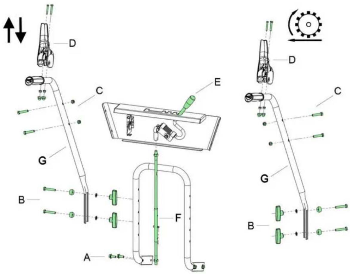
text_image
Technical diagram of a mechanical device with labeled components and directional arrows indicating motion or assembly.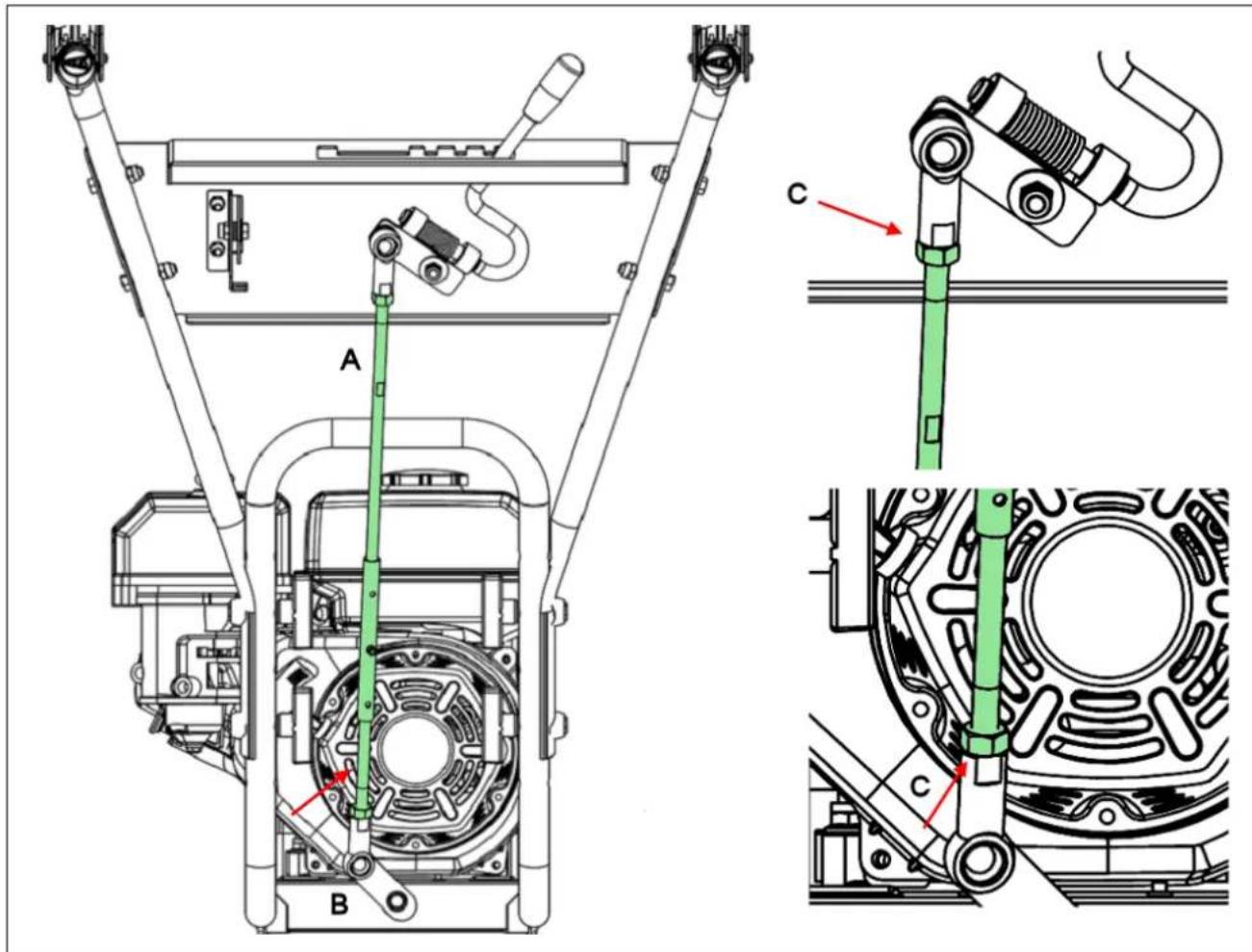
text_image
Technical diagram of a mechanical assembly with labeled components A, B, and C, showing internal components and assembly details.3
text_image
Technical diagram of a vehicle tire assembly with labeled parts A, B, and C4
text_image
Technical diagram showing three stages of a tracked agricultural machine with labeled components and directional arrows5
text_image
Technical diagram of a mechanical device with labeled components A, B, C and directional arrows indicating motion or assembly.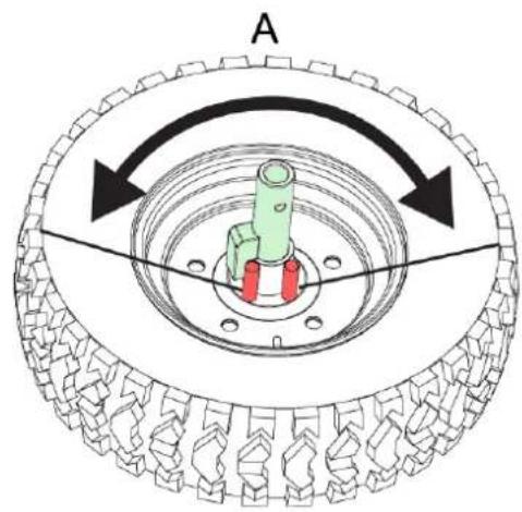
text_image
A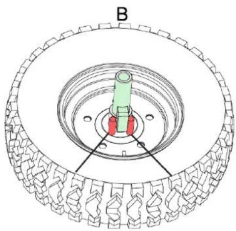
natural_image
Technical diagram of a mechanical assembly with labeled component B, showing concentric gears and central shaft (no text or symbols beyond label)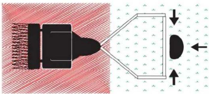
natural_image
Diagram showing a device emitting heat or smoke from a surface, with directional arrows indicating flow or movement (no text or symbols present)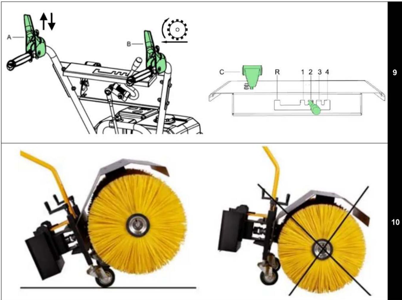
9
10
DK - Original brugsanvisning
GB - Original instructions
Congratulations on purchasing your new Please read this instruction manual carefully, especially the safety warnings marked with the symbol:

Table of contents
| Illustrations | 2 |
| Table of contents | 10 |
| Safety precautions | 10 |
| Miscellaneous | 11 |
| Identification of parts | 11 |
| Assembly | 12 |
| Assembly of accessory | 12 |
| Operation | 12 |
| Operation safety zone | 13 |
| Angle adjustment of accessory | 13 |
| Changing of handlebar height | 13 |
| Storage | 13 |
| Troubleshooting | 13 |
| Technical specifications | 13 |
Spare parts
Spare part drawings for the specific product can be found
on our website www.texas.dk
If you find the part numbers yourself, this will facilitate more rapid service.
For purchase of spare parts, please contact your dealer.
You will find a list of dealers on the Texas website.
Safety precautions
Setup
Do not put hands or feet near or under rotating parts.
Read this manual carefully. Make sure that you are familiar with the different controls, settings and handles of the equipment.
⚠ Know how to stop the unit and ensure that you are familiar with emergency stop.
Never allow children or people unfamiliar with these instructions to use the machine. Note, that local regulations can restrict the age of the operator.
If you feel unwell, tired or have consumed alcohol or drugs, do not operate the machine.
Always inspect the machine before usage. Ensure that no parts are worn or damaged.
⚠️ Replace worn out or damaged elements and bolts in sets to preserve balance.
The operator of the machine is responsible for people's safety.
⚠️ Never use the machine near children or animals.
The operator of the machine is held liable for any accidents or hazards to other people and their property.
Thoroughly inspect the area, where the equipment is to be used, if necessary remove any foreign objects.
Do not refuel gasoline indoors or while the engine is running.
Spilled gasoline is extremely flammable, never refuel while the engine is still hot.
⚠ Wipe off any spilled gasoline before starting the engine. It may cause a fire or explosion!
⚠ Beware of hazards, while working on difficult soil hence; extremely stony or hard soil.
⚠ Boots with non-slip soles with steel jacket is required. Avoid loose-fitting clothes.
Operation
⚠️ Always start the engine from safety zone.
Do not leave the safety zone while operating the machine, if it is necessary to leave the safety zone, turn off the engine before leaving the zone.
After striking a foreign object, stop the engine immediately, remove the spark plug cap and inspect the machine thoroughly for damage. Repair the damage before continuing
If the machine should start to vibrate abnormally, stop the engine and check immediately for the cause. Vibration is generally a warning of damage.
Always disengage the levers, turn off the engine, and remove the spark plug, when the unit is left unattended.
Always turn off the engine and ensure that all moving parts have come to a complete stop before making any repairs, adjustments, or inspections.
Exercise extreme caution when operating on slopes.
⚠️ Never operate the machine at a fast pace.
Do not overload machine capacity by attempting to work at too fast a rate.
Do not carry passengers.
Pay attention, while the machine is in reverse.
⚠️ Never allow any bystanders in front of unit.
⚠️ Always disengage the rotary brush, if not in use.
⚠️ Only operate the machine at daylight or in fully illuminated areas
⚠ Ensure a stable foothold and always keep a firm hold on the handles. Always walk, never run.
Do not operate the equipment when barefoot or wearing sandals.
Exercise extreme caution when changing direction on slopes and do not work excessively steep sloves
By rear tillers, ensure that the blades are protected by safety shield, only the part of the blades that works into the soil must be free.
Never attempt to make any adjustments, while the engine is running.
⚠ Use extreme caution when reversing or pulling the machine backwards
Never operate the engine indoor or in areas with low ventilation. The exhaustion from the engine contains carbon monoxide. Failure to observe could result in permanent injury or death.
Gasoline safety
Use extreme care in handling gasoline. Gasoline is extremely flammable and the fumes are explosive.
! Serious personal injury can occur, when gasoline is spilled on yourself or your clothes. Rinse your skin and change clothes immediately!
⚠ Use only an approved gasoline container. Do not use soft drink bottle or similar!
Extinguish all cigarettes, cigars, pipes and other sources of ignition.
⚠️ Never refuel your machine indoors.
Let the engine cool down before refilling
Never fill the fuel tank to more than 2.5 cm below bottom of filler in order to provide space for fuel to expansion.
After refueling, ensure that the cap tighten securely.
Never use the lock-function on the gasoline gun, when refueling.
Do not smoke while refueling.
! Never refuel inside a building or where gasoline fumes may get in contact with an ignition source.
Keep gasoline and engine away from appliance, pilot lights, barbecues, electric appliances, power tools, etc.
⚠️ If the fuel tank has to be drained, this shall be done outdoors
Maintenance and storage
The engine shall be stopped when carrying out maintenance and cleaning operations, when changing tools and when being transported by means other than under its own power.
⚠️ Check regularly that all bolts and nuts are tightened. Retighten if necessary.
The engine must be completely cooled before storing indoors or covered.
If the machine unused for a period of time, please refer to the instructions in this manual.
Maintain or replace safety and instruction labels, as necessary.
Only use original spare parts or accessories. If not original parts or accessories is used, the liability is no longer applied.
⚠️ Replace faulty silencers.
Miscellaneous
The motor is not pre-filled with oil.
⚠ Factory-fitted control devices, such as the handle-mounted clutch cable, must not be removed or exposed.
Only drain the fuel tank outdoors. Gasoline is extremely flammable and the fumes are explosive.
⚠ Ensure that the machine is properly secured when transported on a flatbed etc.
⚠️ Reduce the throttle during engine shutdown and close the fuel valve.
Identification of parts
Figure 1:
A. Activation of wheels
B. Activation of accessory
C. Gear
D. Throttle
E. Accessory- Snowblade
F. Accessory - Snowthrower
G. Accessory- Sweeper
H. Supporting leg / foot pedal
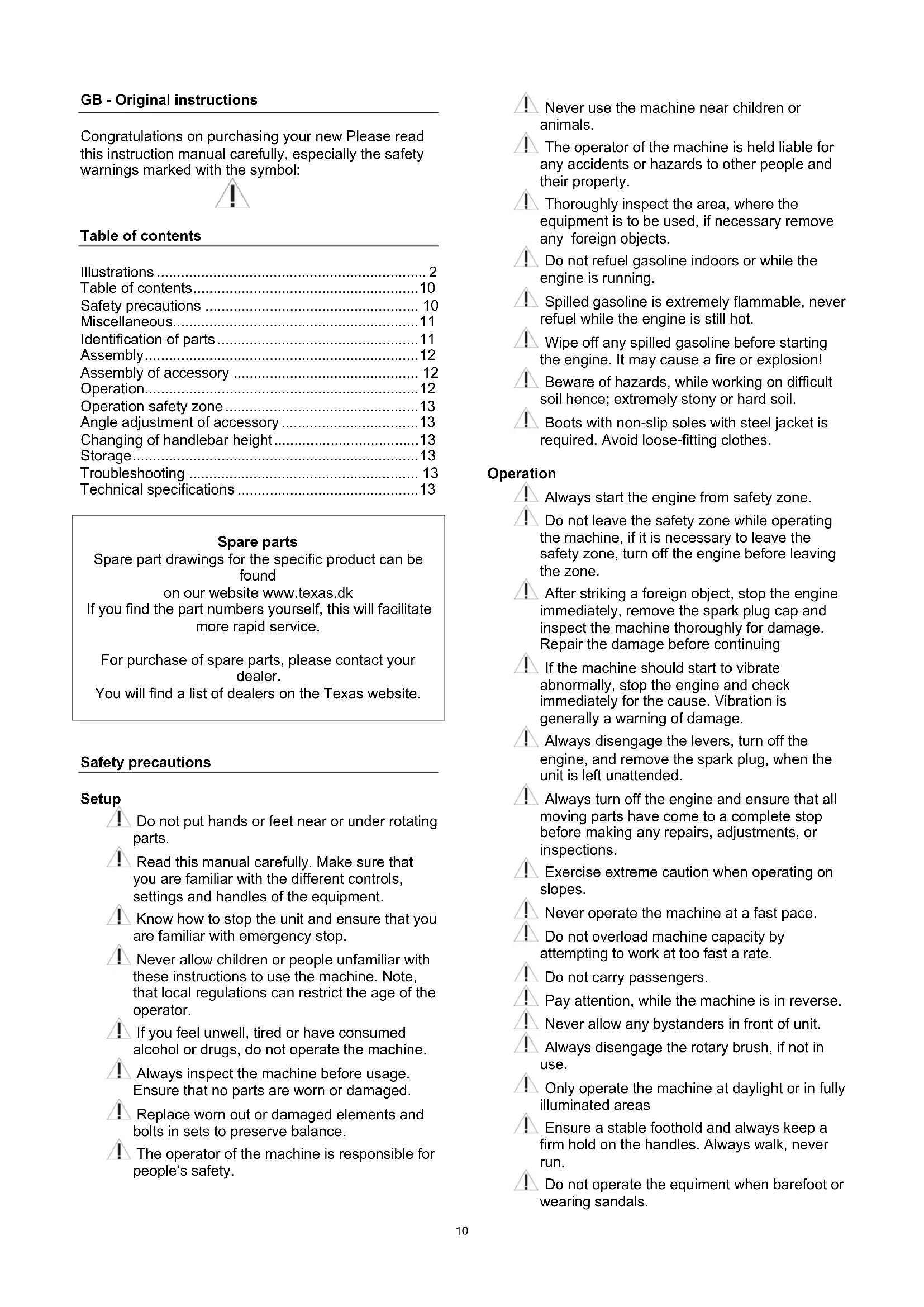
Assembly
The machine is almost ready assembled from the factory. Only a few items remain to be assembled:
Notice: The machine is prepared for assembling the handlebar height in the middle position.
- Install the lower handle on the machine using the supplied bolts and tighten. See fig. 2-A.
- Install the upper handlebar on the lower handlebar using the supplied bolts. See fig. 2-B (Do not tighten at this point)
- Attach the dashboard to the upper handlebar using the supplied bolts. See fig 2-C. (Do not tighten at this point)
- Tighten, the bolts at the upper handlebar on the lower handlebar See fig.2-B.
- Tighten the dashboard bolts. See fig. 2-C.
-
Attach the clutch handles and fix the cables: Handle with arrows should be in left side. Handle with broom should be in right side. See figure 2-D.
-
Mount the gear rod
A. Mount the middle part of the lever fig. 3-A in the bottom of the gear rod fig. 3-B (the short part which is fixed by a bolt should point downwards) and turn it approximately 2 rounds. (note; anticlockwise). The arrow on the gear rod should point towards the top of the machine.
B. Put the gear selector in 4th gear.
C. Mount the middle part of the lever in the gear selector and turn it until it locks.
D. Tighten the middle part by hand until it is tightened in both ends. See fig. 3-C.
E. Loosen then the middle part 1 full round.
F. Tighten both of the nuts on the gearlever.rod. See fig 2-B.
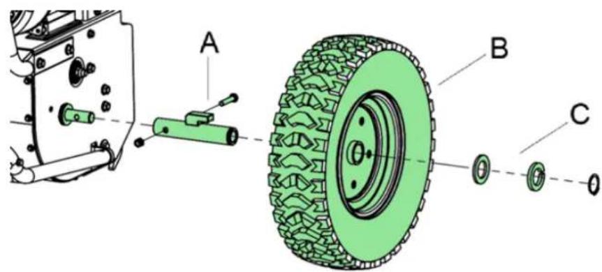
- Mount the axle pole and wheels See fig 4. Note: "Arrow" on the tire should be pointing forward.
Check the tire pressure on both wheels before use. Correct tire pressure is 20 psi/1.4 bar.

Use of machine with too low tire pressure, can damage the tires!
Assembly of accessory
Follow the assembly procedure as shown in fig 5. It is important that the accessory-unit is "clicked" in place by pressing down the foot pedal. See fig, 5-A.
Operation

Read the instruction manual for the engine, before use.
Before using the machine, remove bigger objects from the vicinity. Bigger objects can damage the machine. Also check that all bolts are tightened.

Control always oil level before starting the engine.
Start the engine:
- Open the fuel tap.
- On a cold engine open the choker. Note: By a hot engine choke is not required.
- Push the throttle handle to "Max" position. Fig. 9-C
- Pull the recoil starter gently until you feel resistance in the rope. Then pull quickly and energetic. Do not at any time let go of the recoil starter but glide it gently back and pull again.
- Regulate the choker until the engine is running smoothly.
Stop the engine:
- Pull the throttle handle to "STOP" in order to stop the engine. Fig. 9-C.
Remember to close the fuel valve if the machine will not be used over a longer period!
Clutch Lever A - Forward and Reverse.
To operate the black clutch lever A in fig. 9, the control stick must first be activated By tilting the control stick to the right side and then activate the black handle, the machine will move forward or backwards. To change direction release the clutch lever and choose the desired gear position.
Gear: The machine has 4 forward and 1 reverse gear. To change gear release the clutch lever fig. 6 A and select the disered gear fig 9.
| Speed | 2,3Km/h | 1,5Km/h | 2,9Km/h | 4,4Km/h | 5,8Km/h |

Always release the clutch handle before changing gear!
Snowblower/Snowblade/Sweeper-accessory:
It is recommended only to use first gear in snow depth from 10 cm and above. The snow clearing work deteriorate at speeds above 1.5 km/h.
Pay attention while reversing. It is important that the area is cleared, for any obstacle before reversing. Never reverse the machine against a wall, tree or any other fixed obstacle.
Clutch Lever B - Activation of accessory.
To operate the black brush lever B in fig. 9, the control stick must first be activated. By tilting the red stick completely to the right and then push the lever down activates the accessory
Important! The red control stick on the clutch lever must be pushed to the far right before the clutch lever is activated. If not the clutch lever will forced of its hold. If this happens, push the lever back up and repeat the procedure. See fig. 9 A+B.
Note: The clutch lever is not broken but simply pushed back into place.
The machine is equipped with a "dead man's handle", once released the brush and drive will stop immediately.
Wheel shaft: Fixed vs. free
- Activate free wheel shafts, see fig. 7-A At hard ground (e.g. paved road), it can be a good idea to activate free wheel shafts.
- Activate fixed wheel shafts, see fig. 7-B At soft/lose ground (e.g. dirt road) it can be a good idea to activate fixed wheel shafts
Generally, the machine will be easier to manoeuvre with free wheel shafts.
Operation safety zone
Do not leave the operation safety zone marked in fig 5, while working with the machine. If it is necessary to leave the operation zone, for example to readjust the rotary brush or to attach an accessory, first stop the engine.
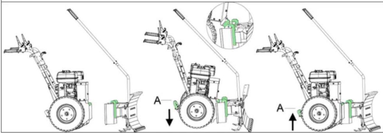
Angle adjustment of accessory
The accessory can be pivoted 20 degrees to either side. This is done by pushing the swing handle down, turning the brush and releases the handle so the detent clicks into place.
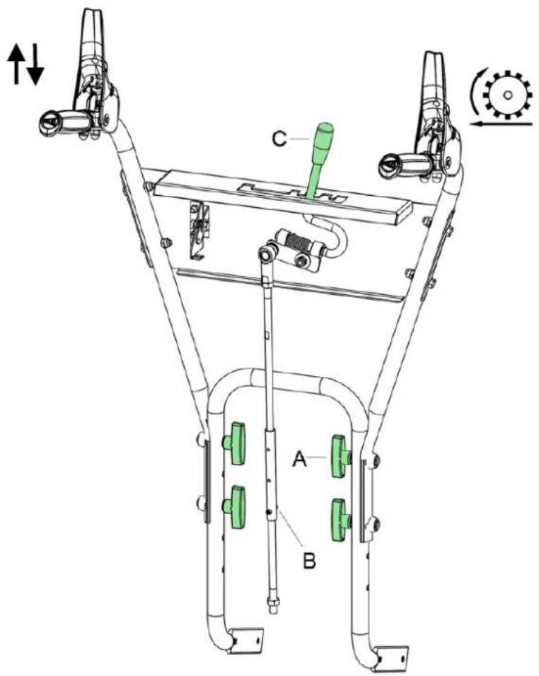
Changing of handlebar height
- Remove the small bolt from the gear rod middle part (fig. 6-B).
- Loosen the 4 bolts on the middle of handlebar (fig. 6-A) and take the out.
- Move the upper handlebar and the gear rod part up/down with same number of holes (fig. 2-F+G)
- Mount all the bolts again on the handlebar and gear rod and tighten them again.
- Check that the gear rod (fig. 6-C) easily can move into all position. If not, the bolt on the gear rod middle part is probably not placed in the correct hole.
Storage

Correct storage of your sweeper!
Store the sweeper, so that the brushes do not touch the ground. This will extend the durability and lifetime of the brushes.
- Lower the support wheels about 50 mm so that the brushes are floating above the ground before the sweeper is disconnected from the basis unit.
- Disconnect the sweeper from the basis unit.
- Tilt the sweeper back, so it rests on the connection-part, and let it stand in that position during the storage period.
Never let the brushes rest on the ground for longer time. It will cause them to bend and be useless. Fig. 10
Troubleshooting
Problem Solution
The engine won't start:
- Check sparkplug.
- Check that the spark plug cap is fitted correctly.
- Check if the motor is equipped with an ignition switch.
(It must be activated) - Check if the motor is equipped with a fuel valve.
(It must be activated)
The engine runs unevenly:
-
Check that the choke has been released.
-
Check fuel for impurities
(or check/clean the carburetor)
If the accessory-unit makes noise or run badly:
- Check that the accessory-unit is clicked in place properly (fig. 5-A).
If the accessory-unit will not run:
- Check that the cable is adjusted correctly.
If the machine will not run:
- Check that the cable is adjusted correctly.
- Check the belt.
If the machine does not sweep effectively:
- Check the distance between the brush and working surface.
Technical specifications
| Length (mm) 800 | 800 800 | ||
| Width (mm) 700 | 700 700 | ||
| Height (mm) 1000 | 1000 1000 | ||
| Weight, dry (kg) 55.5 | 56 55.5 | ||
| Wheel size 4.80-8 | 4.80-8 | 4.80-8 | |
| Engine model | TG725S | TG725ES | 950 |
| Engine brand | Texas | Texas B&S | |
2000/14/EC amended by 2005/88/EC
Materiellet er udført i overensstemmelse med følgende standarder • Conforms with the following standards • In Übereinstimmung mit den folgende Standards • Conformément aux normes suivantes • Материалы соответствуют следующим директивам • Wyrób jest zgodny z następującymi normami
ISO 8437:1989+A1, EN 13019:2001+A1
Combi 800TG/800TGE LWA: 101 dB(A) LPA: 90.6 dB(A) K = 3 dB(A) Combi 800B LWA: 106 dB(A) LPA: 86.1 dB(A) K = 3 dB(A)
Serial numbers: 2003016800000 - 2203024999999
Vibrations a_h = Max 2.99 m/s^2 K = 1.5 m/s^2
Texas Andreas Petersen A/S Knullen 22 • DK-5260 Odense S
Responsible for documentation Johnny Lolk
28.10.2019

text_image
Henry TahnJohnny Lolk Managing Director