
CTB ECOWATT PLUS - Fan Soler & Palau - Free user manual and instructions
Find the device manual for free CTB ECOWATT PLUS Soler & Palau in PDF.
| Product type | Roof extractor fan for mechanical ventilation |
| Brand | Soler & Palau |
| Model | CTB ECOWATT PLUS |
| Power supply | 220-230 V AC, 50 Hz |
| Operating modes | Constant pressure (PI), Constant airflow (CAV), Proportional (VAV), Min/Max, with RTC timer |
| Internal pressure sensor | Yes, range up to 400 Pa (600 Pa for CRVB-N 250) |
| Setpoint adjustment | Via PROSYS ECOWATT console or analog input 0-10 V / 4-20 mA |
| Communication | Modbus RTU (RS485), up to 32 units |
| Compatible accessories | PROSYS ECOWATT console, TIMER RTC ECOWATT timer |
| Analog inputs | 2 inputs (IN1, IN2) 0-10 V or 4-20 mA for external probes |
| Digital input | 1 input (J11) for NO/NC contact (night function or Min/Max) |
| Motor output | Analog signal 0-10 V, TACOM output for revolution counter |
| Alarm relay | 1 relay output (max load 2 A) |
| Model references | CTB-4-500/200, CTB-4-800/250, CTB-4-1300/315, CRHB/CRVB-N |
| Maintenance | Regular cleaning of blades and grilles; disconnect power before intervention |
| Safety | CE marking, comply with safety standards; do not modify the product |
| Warranty | Manufacturer's warranty S&P (see conditions) |
| Recycling | Compliant with EEC directive; dispose of in appropriate recycling containers |
Frequently Asked Questions - CTB ECOWATT PLUS Soler & Palau
User questions about CTB ECOWATT PLUS Soler & Palau
0 question about this device. Answer the ones you know or ask your own.
Ask a new question about this device
Download the instructions for your Fan in PDF format for free! Find your manual CTB ECOWATT PLUS - Soler & Palau and take your electronic device back in hand. On this page are published all the documents necessary for the use of your device. CTB ECOWATT PLUS by Soler & Palau.
USER MANUAL CTB ECOWATT PLUS Soler & Palau
Funcionamiento Modo PROPORCIONAL/VAV
Sensor IN1:
TIMER RTC ECOWATT
7.2. PROGRAMACIÓN
-
INTRODUCTION ...... 35
-
SAFETY REGULATIONS AND "CE" MARKING ....35
-
GENERAL INSTRUCTIONS....35
-
DESCRIPTION 35
4.1. Locations....35
4.2. Wiring diagram and internal board 36
-
OPERATION WITHOUT PROSYS ECOWATT CONSOLE ....37
-
OPERATION WITH PROSYS ECOWATT ACCESSORY CONSOLE 37
6.1. Installation 37
6.2.Description....41
6.3. Using the console....41
6.4. General parameters....42
6.5. Starting the system....42
6.6. Unit configuration via console 43
6.6.1. Change Set Point 43
6.6.2. Change operation mode....43
6.6.3. Operation PI PRESSURE/COP mode 44
6.6.4. Operation PI VOLUME/CAV mode 47
6.6.5. Operation PROPORTIONAL/VAV mode....51
6.6.6.MIN/MAX operation mode 54
- OPERATION WITH TIMER RTC ECOWATT ACCESSORY AND PROSYS ECOWATT CONSOLE ACCESSORY ....55
7.1. Installation 55
7.2. Programming....56
7.3. Summary table setting values....60
- MODBUS COMMUNICATION SYSTEM INTEGRATION ....60
8.1. Basic features of Modbus-RTU control 60
8.2. Modbus memory map 60
- MAINTENANCE 64
- PUTTING OUT OF SERVICE AND RECYCLING 64
1. INTRODUCTION
Thank you for purchasing this appliance. It has been manufactured in full compliance with applicable safety regulations and EU standards. Please read this instruction book carefully, as it contains important information for your safety during the installation, use and maintenance if this product.
Keep it at hand for future reference.
Please check that the appliance is in perfect condition when you unpack it, as all factory defects are covered by the S&P guarantee.
2. SAFETY REGULATIONS AND "CE" MARKING
S&P technicians are firmly committed to research and development of ever more efficient products and in compliance with current safety regulations.
The instructions and recommendations given below reflect current regulations, principally regarding safety, and therefore are based on compliance with general regulations. Therefore, we recommend all people exposed to hazards to strictly follow the safety regulations in force in your country. S&P will not be held liable for any possible harm or damage caused by non-compliance with the safety regulations, as well as caused by modifying the product.
The CE mark and the corresponding declaration of conformity are proof of the product's conformity with current EU regulations.
3. GENERAL INSTRUCTIONS
A hazard analysis of the product has been carried out as provided in the Machine Directive. The manual contains information for all personnel exposed to these hazards, with aim of preventing possible harm or damage due to faulty handling or maintenance.
All maintenance operations (ordinary and extraordinary) must be carried out with the machine switched off and the electrical power supply disconnected.
Before connecting the power supply cable to the terminal strip, make sure the mains voltage corresponds to the voltage indicated on the specifications plate of the unit.
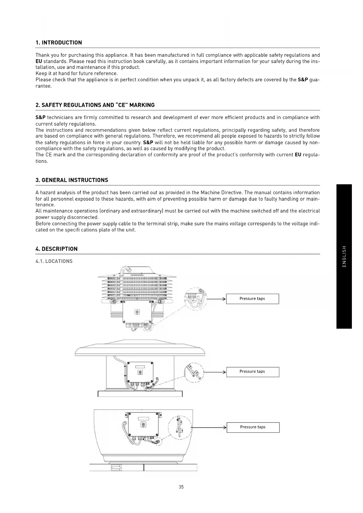
4. DESCRIPTION
4.1. LOCATIONS
IMPORTANT
At the bottom of the control box, two tubes (marked as "V" and "P") come from the inside part of the fan. As the fan is supplied as constant pressure mode (COP), tube "P" is connected and "V" disconnected and blocked with a plastic stopper. To keep this configuration unless chapter 6.6.3. is previously ridden.
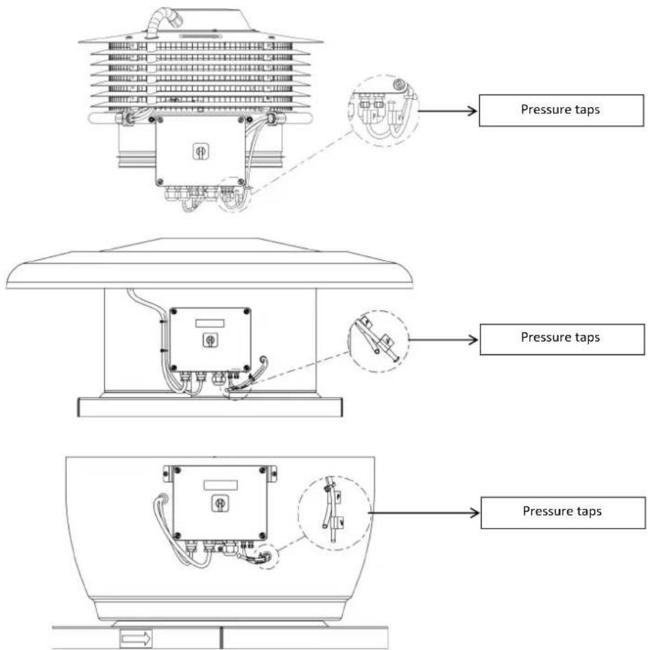
4.2. WIRING DIAGRAM AND INTERNAL BOARD
![graph TD A["TIMER RTC ECOWATT accessory connection"] --> B["PROSYS ECOWATT accessory console connection"] B --> C["Modbus network connection(RS485)"] C --> D["SW1"] D --> E["J9"] E --> F["J12"] F --> G["SW2"] G --> H["J4"] H --> I["SW2-2 Change channel"] I --> J["J5"] J --> K["MODbus network final s…](/content/2026/03/575598/images/b674f1ed5406a77b9a043db2bff475a785ead88678746182e80328be361dc229.jpg)
| Inputs Description | |
| L, N, GND [J1] Power supply. 220-230 V AC 50 Hz | |
| Pressure tap 1 | Tap to connect duct pressure depending on operation mode |
| Pressure tap 2 | |
| Connector (J4) Input to connect with programming schedule TIMER RTC ECOWATT accessory | |
| 0V, IN, +24V (J5) Analog input IN1 4-20 mA ó 0-10V | |
| 0V, IN, +24V (J6) Analog input IN2 4-20 mA ó 0-10V | |
| RJ45 (J9) PROSYS ECOWATT accessory console connection | |
| IND (J11) Digital input for night operation of MIN/MAX function modeIf open, the fan works in night speed or minimum speed when relay is closedIf close, the fan works in night speed or minimum speed when relay is opened | |
Outputs Description
| GND, N, X (J2) | Internal board power supply passing through ON/OFF switch (Factory wired) |
| RELÉ (J3) Commutate if any alarm is activated (2A maximum load) | |
| 0V, +V (J7) Output analog signal 0-10V to the motor | |
| TACOM (J8) Pulse motor | |
| A, B (J10) Network connection. Modbus protocol | |
| RS485 (J12) Network connection. Modbus protocol | |
Micro switches Description
| SW1 End of line resistor. Exclusive use for Modbus communication network |
| SW2 SW2-2: enable cannel change |
5. OPERATION WITHOUT PROSYS ECOWATT CONSOLE
Roof fans CTB, CRHB/CRVB-N ECOWATT PLUS are ready to work on constant pressure mode (COP/PI PRESSURE) with a differential pressure reading taken on inlet side and a predefined set point from factory (100Pa).
6. OPERATION WITH PROSYS ECOWATT ACCESSORY CONSOLE
Acquiring the PROSYS ECOWATT console offered as an optional accessory, you will have access to the following operation modes:
- Constant pressure system (PI PRESSURE/COP) with modifi able set point parameters.
- Constant airflow system PI VOLUME/CAV with modifiable set point parameters.
- Variable airflow system PROPORTIONAL/VAV (it is necessary to install an external sensor with an output analog signal 0-10V or 4-20mA).
- MIN/MAX operating system (it is necessary to install an external sensor with an output digital signal, time clock or external relay).

PROSYS ECOWATT
6.1. INSTALLATION
It is possible to install a single PROSYS ECOWATT console linked with one CTB/CRHB/CRVB-N ECOWATT PLUS, or make a Modbus communication network linking more than one unit with one PROSYS ECOWATT console.
Individual control wiring diagram
Multiple control wiring diagram
It is possible to connect up to 32 fans between them to create a communication network that can be adjusted and controlled with a single PROSYS ECOWATT console.
![graph TD A["PROSYS ECOWATT"] --> B["CTB/CRHB/CRVB ECOWATT PLUS PCB (n°1)"] B --> C["RS485"] B --> D["SW1=OFF"] B --> E["RS485"] B --> F["SW1=OFF"] B --> G["RS485"] B --> H["SW1=ON"] style A fill:#f9f,stroke:#333 style B fill:#ccf,stroke:#333 style C fill:#cfc,stroke:#333 style D fill:#fcc,stroke:#33…](/content/2026/03/575598/images/85f6331a10bd575e05f6de2e1f5af0d5a408b66ad0c869737a771e2ed0a03d82.jpg)
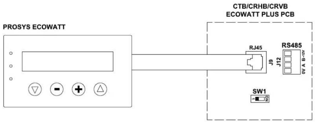
To change the fan number should follow these steps:
![graph TD A["ENTER PASSWORD: 1 1 1 OK"] --> B["CHANGE PASSWORD? NO YES"] B --> C["SETUP MENU CHANNEL N:1 OK"] C --> D["FACTORY SETTING? NO YES"] D --> E["MODE <PI PRESSURE OK"] E --> F["MIN-OUTPUT < 20% OK"]](/content/2026/03/575598/images/2e24b0e2253afc73e19c2140aeb7218e0e753f1570f0176d9c3dcb0e111076a8.jpg)
Press simultaneously for 3"
Enter the password
Default: 1 1 1
It is possible to assign a new password to your device
Selection on which cannel you want to set the fan
Press on "NO" to do not return to Factory setting
Press on "OK"
Press on "OK"

Press on "OK"


Press on "NO"

Press on "YES" to save changes


6.2. DESCRIPTION
The PROSYS ECOWATT is used as a visualization and control supplement. Following functions are possible: • Display parameters and variables - Save settings - Display settings - Configure your device and operating modes - Search units (channels) in the network (previously each unit should be configured with different number of channels) The console has a LCD display of 2x16 characters, 4 buttons and 3 LED's. - Button "Up" - Button "Down" - Button "+" - Button “-” • LED power supply ON • LED "activity" Modbus - LED error 6.3. USING THE CONSOLE
When modifying the configured parameter, the buttons on the console have the following functions:| Button Function | |
| Increase parameter value | |
| Decrease the parameter value | |
| Enter | |
| Exit | |
| Button Function | |
| Modify the value of 1st digit | |
| Modify the value of 2nd digit | |
| Modify the value of 3rt digit | |
| OK. Validate | |
| Button Function | |
| NO = Exit | |
| Reduce cannel value | |
| Increase cannel value | |
| YES = Validate | |
6.4. GENERAL PARAMETERS
Once the wiring is done, turn on the device using the ON/OFF switch. When connecting the unit it will appear some screens:  After choosing the language, a screen with the following information will appear:  Si: xxx Measured value (units depend on operation mode) Sp/Sc: xxx Set point programmed X% Fan speed in % (on high speed) C: 1 Fan number if connected to network Pressing the button △ can access the second screen of information:  RPM: xxx Fan speed (TACOM terminals connected is required) Rele: 0 It Indicates if the alarm output relay is connected (0: offline output; 1: output connected) InD: 0 Digital input (J11 night mode or Min/Max)(0: off line output; 1: output connected) C: 1 Communication cannel used (de 1 a 247)6.5. STARTING THE SYSTEM
Once done the wiring and configuration of existing units, proceed to the system power supply. When connecting the unit, it will appear the initial screen with Software version, after 3 seconds will initiate the connection with number of memorized unit. If communication is successfully, it will appear the first information screen. Corresponding screen of PI PRESSURE mode will appear by default:  6.6. UNIT CONFIGURATION VIA CONSOLE
6.6.1. Change Set Point
Steps to follow to change the set point from main screen:| Si:XXX | x2 |
| Sc:XXX | C1 |
6.6.2. Change operation mode
Once the unit is powered, desired language selected and showing screen described above, continue with following sequence:   3"  Press simultaneously for 3" ENTER PASSWORD: 1 1 1 OK  Enter the password Default: 1 1 1 CHANGE RE lack SI NO  It is possible to assign a new password to your device (channel) NEW CONTO CHANNEL N: 1 OK Selection on which cannel you want to set the configuration At this time we are in configuration mode and it is possible to navigate and select parameters desired:  Operation: depending on mode selected, displayed parameters will be specific to each one. Ending "RTC" modes are only activated in combination with programming schedule TIMER RTC accessory.6.6.3. Operation PI PRESSURE/COP mode
In section 5 we have described that the fan comes from factory ready to work in constant pressure mode. However, it is also possible to connect an external pressure transducer (0-10V or 4-20mA) that should be connected to J5 or J6 terminals.  Operation PI PRESSURE/COP mode After selecting the operating PI PRESSURE/COP mode, you can configure following parameters:  Press + to manually modify the minimum output parameter to the motor Press or to manually modify the maximum output parameter to the motor  Sensor: Sensor type INTERNAL: Pressure differential inte - IN1 0-10V: External sensor with analog signal 0-10V (J5 terminal) - IN1 4-20mA: External sensor with analog signal 4-20mA (J5 terminal) - IN2 0-10V: External sensor with analog signal 0-10V (J6 terminal) - IN2 4-20mA: External sensor with analog signal 4-20mA (J6 terminal) RANGE < 400Pa OK    Pulsar para modificar manualmente el parámetro. El valor que aparece en pantalla corresponde a la escala del sensor interno preajustado en fábrica. Si se instala un sensor externo, introducir el rango de escala correspondiente.  Set Point: \- INTERNAL: CONSOLE: Factory set value Value set by PROSYS E - IN1/IN2 0-10V: Value set by external potentiometer (0-10V) - IN1/IN2 4-20mA: Value set by external potentiometer (4-20mA)  Press + or to manually modify this parameter. It is advised not to modify. Press + or - to manually modify this parameter. It is advised not to modify. Press + or - to manually modify this parameter. It is advised not to modify.  Press + to manually modify this parameter. This value corresponds to the % of pressure set point being the fan in night mode. To connect a time clock or potential-free switch to the digital input J11  DIGITAL INPUT < I NDigital input:
- NC: Normally closed contact. The fan will pass to night mode when contact is opened. - NO: Normally open contact. The fan will pass to night mode when contact is closed.  Press + to manually modify parameter that displays the speed by J8 output (TACOM). It is advised not to modify.  Save parameters modified   Press any key to return to main screen  6.6.4. Operation PI VOLUME/CAV mode
Before selecting PI VOLUME/CAV mode using PROSYS ECOWATT console, it is necessary to change pressure taps configuration. Place tubes marked with "V" and "P" as is represented below.   Operation PI VOLUME/CAV mode Once changed the operation mode to PI VOLUME/CAV, following parameters will appear:  Press + to manually modify the minimum output parameter to the motor Press for to manually modify the minimum output parameter to the motor Access to advanced configuration parameters Enter the password Default: 1 1 1 It is possible to assign a new password to your device (channel) No modify  Sensor: Sensor type INTERNAL: Pressure differential internal s \- IN1 0-10V: External sensor with analog signal 0-10V (J5 terminal) \- IN1 4-20mA: External sensor with analog signal 4-20mA (J5 terminal) \- IN2 0-10V: External sensor with analog signal 0-10V (J6 terminal) \- IN2 4-20mA: External sensor with analog signal 4-20mA (J6 terminal)  \- IN1/IN2 0-10V: Value set by external potentiometer (0-10V) \- IN1/IN2 4-20mA: Value set by external potentiometer (4-20mA)  Factory set value Value set by PROSYS ECOWAT T  Press + to manually modify this parameter. It is advised not to modify. Press + to manually modify this parameter. It is advised not to modify. Press + or to manually modify this parameter. It is advised not to modify. Press + to manually modify this parameter. This value corresponds to the % of pressure set point being the fan in night mode. To connect a time clock or potential-free switch to the digital input J11  DIGITAL INPUT < (NO) OKDigital input:
- NC: Normally closed contact. The fan will pass to night mode when contact is opened. - NO: Normally open contact. The fan will pass to night mode when contact is closed. Press ☐ to manually modify parameter that displays the speed by J8 output (TACOM). It is advised not to modify. Save parameters modified  Press any key to return to main screen6.6.5. Operation PROPORTIONAL/VAV mode
In this mode the control box is ready to work with one or two analog inputs (4-20mA or 0-10V). The control box works according to the parameter of maximum demand. Sensors are connected to the analog inputs J5 and/or J6.  Operation PROPORTIONAL/VAV mode Once changed the operation mode to PROPORTIONAL/VAV, following parameters will appear: Sensor IN1:
- NO SENSOR: No sensor connected to this input - 0-10V/4-20mA %HR: Humidity sensor with output analog signal 0-10V/4-20mA - 0-10V/4-20mA TEMP: Temperature sensor with output analog signal 0-10V/4-20mA - 0-10V/4-20mA CO2: CO2 sensor with analog signal 0-10V/4-20mA  Press + to modify the scale of the external sensor used  Press + or - to modify manually the middle range of use. Press + to modify manually the width value of the adjustment range of the sensor Follow the same process if you select a different sensor type or activated the second input analog signal SENSOR IN2.  Press or to manually modify the minimum output parameter to the motor  Press + to manually modify the maximum output parameter to the motor  Access to advanced configuration parameters  Enter the password Default: 1 1 1  It is possible to assign a new password to your device (channel)   No modify Press ☐ to modify manually this parameter. This value allows you to send an alarm message when measured by sensor IN1 value reaches a percentage of measuring range Press 🧑 to modify manually this parameter. This value allows you to send an alarm message when measured by sensor IN2 value reaches a percentage of measuring range Press 🧑 to modify manually this parameter. This send an alarm message when the fan speed value reaches a minimum value Press + to manually modify parameter that displays the speed by J8 output (TACOM). It is advised not to modify. Save parameters modified Press any key to return to main screen6.6.6. MIN/MAX operation mode
In this mode, the control box is ready to work by contact type normally open (NO) or normally closed (NC), located at the digital input J11. When the status of this input changes, the fan goes to low speed with a set value in % of maximum speed.Logic:
- NO (normally open): The fan pass to low speed when contact is closed. - NC (normally closed): The fan pass to low speed when contact is open.  Operation mode MIN/MAX Once changed the operation mode to MIN/MAX, following parameters will appear:  Press + to manually modify the minimum output parameter to the motor Press for to manually modify the maximum output parameter to the motor Access to advanced configuration parameters Enter the password Default: 1 1 1 It is possible to assign a new password to your device (channel)     No modify  DIGITAL INPUT < (NC) OKDigital input:
- NC: Normally closed contact. The fan will pass to night mode when contact is opened. - NO: Normally open contact. The fan will pass to night mode when contact is closed.       Press to manually modify parameter that displays the speed by J8 output (TACOM). It is advised not to change. Save parameters modified Press any key to return to main screen7. OPERATION WITH TIMER RTC ECOWATT ACCESSORY AND PROSYS ECOWATT CONSOLE ACCESSORY
Acquiring the programming Schedule TIMER RTC ECOWATT offered and accessory, you will have access to functions described in section 6 Operation with PROSYS ECOWATTaccessory console, in addition to program the following: - Up to three periods per day with desired set pointa - Holiday period by scheduling date and start/end time and % over maximum speed7.1. INSTALLATION
As shown in figure below, this accessory is an electronic component that must be installed inside the roof fan control box.  TIMER RTC ECOWATT In order to do it correctly, follow these steps: 1. Disconnect power supply from the frontal ON/OFF switch 2. Open control box 3. Locate the J4 connector  4. Line up electronic component TIMER RTC ECOWATT with J4 connector pins  5. Fit the accessory pressing down 7.2. PROGRAMMING
During programming process must define following parameters: • T1, T2, T3: Start time for each period frame (OFF, 00:00-23:59). - Period T1, Period T2, Period T3: Minutes of each time period related to start time defined (until 480 minutes). - Set point T1, Set point T2, Set point T3: Set point in % during period frame over operation mode previously selected (e.g. if PI PRESSURE+RTC mode is selected and set point T1 is 50%, during period frame the fan will reduce the speed accordingly with a minus 50% of the pressure set point defined). Example:| MONDAY TUESDAY ... SATURDAY SUNDAY | |||||
| 1:00 | T3 = 480 minSetpointT3 = 25% | T3 = 480 minSetpointT3 = 25% | T3 = 480 minSetpointT3 = 25% | T3 = 480 minSetpointT3 = 25% | |
| 2:00 | |||||
| 3:00 | |||||
| 4:00 | |||||
| 5:00 | |||||
| 6:00 | |||||
| 7:00 | |||||
| 8:00 | T1 = 60minSetpointT1 = 50% | T1 = 60minSetpointT1 = 50% | |||
| 9:00 | T2 = 120 minSetpointT1 = 50% | T2 = 120 minSetpointT1 = 50% | |||
| 10:00 | T1 = 60minSetpointT1 = 50% | T1 = 60minSetpointT1 = 50% | |||
| 11:00 | |||||
| 12:00 | |||||
| 13:00 | |||||
| 14:00 | T2 = 120 minSetpointT1 = 50% | T2 = 120 minSetpointT1 = 50% | |||
| 15:00 | |||||
| 16:00 | |||||
| 22:00 | |||||
| 23:00 | T3 = 480 minSetpointT3 = 25% | T3 = 480 minSetpointT3 = 25% | T3 = 480 minSetpointT3 = 25% | T3 = 480 minSetpointT3 = 25% | |
| 0:00 | |||||
7.3. SUMMARY TABLE SETTING VALUES
| Registro Min. Max. Description | ||
| T1 | ||
| T2 | OFF 23:59 Start time period frame | |
| T3 | ||
| Period T1 | ||
| Period T2 | 0min 480min Period frame duration | |
| Period T3 | ||
| Set T1 | ||
| Set T2 | OFF 100% Percentage over set point | |
| Set T3 | ||
| Date start | 00:00 23:59 Starting date holidays period | |
| Hour start | 00:00 23:59 Starting hour holidays period | |
| Date end | 00:00 23:59 Ending date holidays period | |
| Hour end | 00:00 23:59 Ending hours holidays period | |
| Set Holidays | OFF 100% Percentage over the set point for holidays period | |
8. MODBUS COMMUNICATION SYSTEM INTEGRATION
8.1. BASIC FEATURES OF MODBUS-RTU CONTROL
| Addressing | Slave: configurable address from 1 to 247 | Master: able to adress slaves with address from 1 to 247 |
| Diffusion Yes | ||
| Transmissions speed 9600 (19200 is recommended too) | ||
| Parity | PAR/EVEN | |
| Mode | RTU | |
| Electrical interface | RS485 2W-wired or RS232 | |
| Connector type | RJ 45 | |
| Direction | Function | Dates | CRC verification |
| 8 bits | 8 bits | N x 8bits | 16 bits |
8.2. MODBUS MEMORY MAP
Holding registers| N°REG. | Register | Min. | Max. | Description | Default | Comments |
| 0 | TipoMotor | 0 | 1 | 0=AC1=DC | 1 | Motor type |
| 1 | ModoFun | 0 | 7 | 0=PI_Presión1=PI_Caudal2=Proporcional3=Max-Min4=PI_Presión+RTC5=PI_Caudal+RTC6=Proporcional+RTC7=Max-Min+RTC | 0 | Operation mode |
| N°REG. | Register | Min. | Max. | Description | Default | Comments | |
| 2 SensorPI 0 4 | 0=Interno1=IN1 0-10V2=IN1 4-20mA3=IN2 0-10V4=IN2 4-20mA | 0 | Sensor type in PI PRESSURE or PI VOLUME mode | ||||
| 3 Sensor1 0 7 | 0=NO1=0-10V %HR2=4-20mA %HR3=0-10V °C4=4-20mA °C5=0-10V CO26=4-20mA CO27=NTC 100K | 0 | Sensor type in PROPORTIONAL mode and analog input signal 1 | ||||
| 4 Sensor2 0 6 | 0=NO1=0-10V %HR2=4-20mA %HR3=0-10V °C4=4-20mA °C5=0-10V CO26=4-20mA CO2 | 0 | Sensor type in PROPORTIONAL mode and analog input signal 2 | ||||
| 5 PIRange | 5050100 | 125025009900 | SensorPI=0SensorPI<>0Sensor<>0 | 400Pa600Pa[CRVB-N 250] | Range sensor in PI PRESSURE mode | ||
| 6 SetPoint 0 5 | 0=Interno1=IN1 0-10V2=IN1 4-20mA3=IN2 0-10V4=IN2 4-20mA5=ConsolaMODBUS(PROSYS ECOWATT) | 5 | Set point in PI PRESSURE mode | ||||
| 7 Kp 1 250 Increases 1 20 | Proportional constant in PI PRESSURE mode | ||||||
| 8 | Ki | 1 250 | Increases 1 20 | Integral constant in PI PRESSURE mode | |||
| 9 Kq | 50 | 300 Increases 1 | 100[CTB/4-500/200]84[CTB/4-800/250]94[CTB/4-1300/315]70[CRVB-N 250]88[CRHB/CRVB-N 280]112[CRHB/CRVB-N 315]147[CRHB/CRVB-N 355] | Airflow constant with pressure sensor | |||
| 10 | PulsosEncoder | 0 16 | Increases 1 | 2[CTB/4-400/160][CTB/4-500/200]5[CTB/4-800/250][CTB/4-1300/315]1CRVB-N 250CRHB/CRVB-N 280CRHB/CRVB-N 315CRHB/CRVB-N 355 | Number of pulses for encoder lap | ||
| 11 | MinOut | 0 | 50 | Increases 5% | 0 | Minimum output value | |
| 12 | MaxOut | 50 | 100 | Increases 5% | 100 | Maximum output value | |
| 13 | S1Alarm | 0 | 100 | Increases 5% | 90 | Analog input 1 alarm | |
| 14 | S2Alarm | 0 | 100 | Increases 5% | 90 | Analog input 2 alarm | |
| 15 | MinRPM | 100 | 500 | Increases de 100 | 400 | Min RPM alarm | |
| 16 | VacMIN | 80 | 150 | Increases de 10 | 80 | Minimum voltage AC motor | |
| 17 | IN1 Range | 000 | 100502000 | %HR incrementos°C incrementosPPM incrementos | 100 | Background scale in proportional mode input 1 | |
| 18 IN2 Range | 000 | 100502000 | %HR Increases°C IncreasesPPM Increases | 100 | Background scale in proportional mode input 2 | ||
| 19 IN1 Set 0 IN1 Range Increases de 1 50 | Set point proportional mode input 1 | ||||||
| 20 IN1 Banda 0 IN1 Range Increases de 1 25 | Margin (+/-) centered in IN1 Set | ||||||
| 21 IN2 Set 0 IN2 Range Increases de 1 50 | Set point proportional mode input 2 | ||||||
| 22 IN2 Banda 0 IN2 Range Increases de 1 25 | Margin (+/-) centered in IN2 Set | ||||||
| 23 InD 0 1 | 0=NO1=NC | 0 Digital input inverter | |||||
| 24 | setMODBUS | 1 | PIRange | Increases de 50 | 0 | MODBUS set point | |
| 25 | IDIOMA 0 3 | 0=ENGLISH1=SPANISH2=FRENCH3=GERMAN | 0 | Language | |||
| 26 | SP-2 PRESION | 25 100 | Increases de 1 25 | Night set point in PI PRESSURE mode | |||
| 27 SP-2 CAUDAL 50 100 | Increases de 1 50 | Night set point in PI VOLUME mode | |||||
| 28 | SP Temp | -10 | 50 | Increases de 1 | Temperature set point [only for CTBH ECOWATT models] | ||
| 29 | adMODBUS | 10 | 247100 | Increases de 1 | 1 | ||
| 30 | ALARMA | 0 1 | |||||
| 31 | FECHA | 0x0000 | 0xfe7f | Day/Month/Year | 0x088E | Current date | |
| 32 | HORA | 0x0000 | 0x3dfb | Hour/Minute | 0x0000 | Current date | |
| 33 | LUNES T1 | 0x0000 | 0x063b | Hour/Minute | 0x0200 | Starting period 1 Monday | |
| 34 | LUNES T2 | 0x0000 | 0x063b | Hour/Minute | 0x0300 | Starting period 2 Monday | |
| 35 | LUNES T3 | 0x0000 | 0x063b | Hour/Minute | 0x0480 | Starting period 3 Monday | |
| 36 | MARTES T1 | 0x0000 | 0x063b | Hour/Minute | 0x0200 | Starting period 1 Tuesday | |
| 37 | MARTES T2 | 0x0000 | 0x063b | Hour/Minute | 0x0300 | Starting period 2 Tuesday | |
| 38 | MARTES T3 | 0x0000 | 0x063b | Hour/Minute | 0x0480 | Starting period 3 Tuesday | |
| 39 | MIERCOLES T1 | 0x0000 | 0x063b | Hour/Minute | 0x0200 | Starting period 1 Wednesday | |
| 40 | MIERCOLES T2 | 0x0000 | 0x063b | Hour/Minute | 0x0300 | Starting period 2 Wednesday | |
| 41 | MIERCOLES T3 | 0x0000 | 0x063b | Hour/Minute | 0x0480 | Starting period 3 Wednesday | |
| 42 | JUEVES T1 | 0x0000 | 0x063b | Hour/Minute | 0x0200 | Starting period 1 Thursday | |
| 43 | JUEVES T2 | 0x0000 | 0x063b | Hour/Minute | 0x0300 | Starting period 2 Thursday | |
| 44 | JUEVES T3 | 0x0000 | 0x063b | Hour/Minute | 0x0480 | Starting period 3 Thursday | |
| 45 | VIERNES T1 | 0x0000 | 0x063b | Hour/Minute | 0x0200 | Starting period 1 Friday | |
| 46 | VIERNES T2 | 0x0000 | 0x063b | Hour/Minute | 0x0300 | Starting period 2 Friday | |
| 47 | VIERNES T3 | 0x0000 | 0x063b | Hour/Minute | 0x0480 | Starting period 3 Friday | |
| 48 | SABADO T1 | 0x0000 | 0x063b | Hour/Minute | 0x0200 | Starting period 1 Saturday | |
| 49 | SABADO T2 | 0x0000 | 0x063b | Hour/Minute | 0x0300 | Starting period 2 Saturday | |
| 50 | SABADO T3 | 0x0000 | 0x063b | Hour/Minute | 0x0480 | Starting period 3 Saturday | |
| 51 DOMINGO T1 0x0000 0x063b Hour/Minute 0x0200 Starting period 1 Sunday | |||||||
| 52 DOMINGO T2 0x0000 0x063b Hour/Minute 0x0300 Starting period 2 Sunday | |||||||
| 53 DOMINGO T3 0x0000 0x063b Hour/Minute 0x0480 Starting period 3 Sunday | |||||||
| 54 TIEMPO T1 0 480 1 60 | Time in minutes for period 1 | ||||||
| 55 TIEMPO T2 0 480 1 60 | Time in minutes for period 2 | ||||||
| 56 TIEMPO T3 0 480 1 60 | Time in minutes for period 3 | ||||||
| 57 CONSIGNA T1 0 100 1 80 | Percentage about set point | ||||||
| 58 CONSIGNA T2 0 100 1 60 | Percentage about set point | ||||||
| 59 | CONSIGNA T3 | 0 | 100 | 1 | 100 | Percentage about set point | |
| 60 | FECHA INICIO | 0 | 0xfe7f | Day/Month/Year | 0x088E | Starting date holiday period | |
| 61 HORA INICIO | 0x0000 0x063b Hour/Minute | 0 | Starting hour/minute holiday period | ||||
| 62 | FECHA FIN | 0 | 0xfe7f | Day/Month/Year | 0x088E | Ending date holiday period | |
| 63 | HORA FIN | 0x0000 0x063b Hour/Minute | 0 | Ending hour/minute holiday period | |||
| 64 | CONSIGNA VAC | 0 | 100 | 1 | 20 | Holiday period set point | |
| 65 VERSION 0 250 1 | Read-only | ||||||
| 66 | BAUDRATE | 0 | 3 | 0=192001=96002=48003=2400 | 1 | Transmission speed | |
| 67 PARITY | 0 | 2 | 0=No1=Even2=Odd | 1 | Parity MODBUS network | ||
| Register | Min. | Max. | Description | Default | Comments | Comments |
| 0 | Pote | 0 255 | Potentiometer RV1 PCB | Potentiometer RV1 | ||
| 1 | In1 | 0 | 255 | Analog input 1 | Entrada Analógica 2 | |
| 2 | In2 | 0 | 255 | Analog input 2 | Entrada Analógica 2 | |
| 3 | Interno | 0 1250 | Internal pressure sensor | Internal pressure sensor | ||
| 4 | Rpm | 0 | 6000 | Motor speed | Speed motor (if rpm<100, rpm=0) |
| Register | Min. | Max. | Description | Default | Comments | Comments |
| 0 | InD | 0 | 1 | Digital input | Digital input |
| Register | Min. | Max. | Description | Default | Comments | Comments |
| 0 | Output | 0 | 1 | Relay | Relay |
9. MAINTENANCE
Before manipulating the fan, make sure it is disconnected from the mains supply even if it has previously been switched off. Prevent the possibility of anyone else connecting it while it is being manipulated. Fan unit must be regularly inspected. These inspections should be carried out bearing in mind the machine's working conditions, in order to avoid dirt or dust accumulating on blades, impeller, motor or grids. This could be dangerous and perceptibly shorten the working life of fan unit. While cleaning, great care should be taken not to unbalance blades or impeller. All maintenance and repair work should be carried out in strict compliance with each country's current safety regulations.10. PUTTING OUT OF SERVICE AND RECYCLING
 EEC legislation and our consideration of future generations mean that we should always recycle materials where possible; please do not forget to deposit all packaging in the appropriate recycling bins. If your device is also labeled with this symbol, please take it to the nearest Waste Management Plant at the end of its servicable life.SOMMAIRE
1. GÉNÉRALITÉS....66 2. NORMES DE SECURITES ET MARQUAGE "CE" 66 3. NORMES GENERALES....66 4. DESCRIPTION 66 4.1. Emplacements....66 4.2. Branchement électrique et détail plaque interne....67 5. FONCTIONNEMENT SANS CONSOLE PROSYS ECOWATT....68 6. FONCTIONNEMENT AVEC ACCESSOIRE CONSOLE PROSYS ECOWATT 68 6.1.Installation....68 6.2.Description....72 6.3. Utilisation de la console....72 6.4. Paramètres généraux....73 6.5. Mise en marche du système....73 6.6. Configuration des équipements par la console 74 6.6.1. Changement de Consigne 74 6.6.2. Changement de mode de fonctionnement....74 6.6.3. Fonctionnement mode PI PRESSION/COP 75 6.6.4. Fonctionnement mode PI DEBIT /CAV 79 6.6.5. Fonctionnement mode PROPORTIONNEL / VAV....82 6.6.6. Fonctionnement mode MIN-MAX....85 7. FONCTIONNEMENT AVEC ACCESSOIRE DE PROGRAMMATION HORAIRE TIMER RTC ECOWATT AVEC L'ACCESSOIRE CONSOLE PROSYS ECOWATT 87 7.1. Installation 87 7.2. Programmation....88 7.3. Tableau résumé valeurs de réglage 91 8. INTÉGRATION DANS LE SYSTÈME DE COMMUNICATION MODBUS 91 8.1. Caractéristiques de base du contrôle Modbus-RTU 91 8.2. Plan de mémoire Modbus....92 9. MAINTENANCE 95 10. MISE HORS SERVICE ET RECYCLAGE 951. GÉNÉRALITÉS
Avant d'installer et d'utiliser ce produit, lire attentivement ces instructions qui contiennent d'importantes indications pour votre sécurité et celle des utilisateurs, pendant l'installation, l'utilisation et l'entretien de ce produit. Une fois l'installation terminée, laisser ce manuel à la disposition de l'utilisateur fi nal. Dès réception, vérifier le parfait état de l'appareil étant donné que tout défaut d'origine est couvert par la garantie S&P. A la réception de celui-ci, nous vous conseillons vivement de vérifier qu'il n'a pas été endommagé pendant le transport. Dans ce cas, envoyer une lettre avec A.R. au transporteur. En effet, celui-ci est seul responsable des dégâts causés lors du transport. Ne pas laisser l'emballage à portée des enfants et le recycler en accord avec les normes en vigueur.2. NORMES DE SECURITES ET MARQUAGE "CE"
Toujours à la pointe de l'innovation, nos équipes d'ingénieurs n'ont de cesse de développer des produits de plus en plus performants conformes aux normes de sécurité en vigueur. Les normes et conseils, contenus dans ce manuel, se réfèrent aux normes standards en application et par conséquent, sont basés sur la conformité avec les normes générales. Ainsi, nous conseillons vivement à toutes les personnes concernées d'appliquer les règles en vigueur dans leurs pays en matière de prévention d'accidents. La responsabilité de S&P ne saurait être engagée pour dés éventuels dommages corporels et/ou matériels causés lorsque les consignes de sécurité n'ont pas été respectées ou suite à une modification du produit. Le marquage CE ainsi que les déclarations de conformité certifient la conformité aux normes européennes en vigueur.3. NORMES GENERALES
L'analyse des risques associée au produit a été réalisée comme prévu dans la Directive Machines. Les dispositifs de protection ne doivent pas être enlevés sauf en cas d'absolue nécessité. Dans ce cas, des mesures appropriées seront immédiatement adoptées pour signaler explicitement le danger. Dés que possible, les dispositifs de protection doivent impérativement être rétablis. Toutes les interventions de maintenance (régulières ou occasionnelles) se feront alimentation électrique coupée. Avant de brancher le câble d'alimentation électrique de l'appareil, il convient de s'assurer que la tension est conforme à celle indiquée sur le produit.4. DESCRIPTION
4.1. EMPLACEMENTS
IMPORTANT
Dans la partie inférieure du boîtier de commande vous pourrez voir deux tubes repérés par les lettres « V » et « P » provenant de l'intérieur de l'extracteur de toit. L'équipement sort d'usine avec le tube marqué « P » connecté avec le tube « V » déconnecté et bouché par un bouchon. Laissez cette installation en l'état sauf si vous avez lu au préalable le paragraphe 6.6.3 de ces instructions. 4.2. BRANCHEMENT ÉLECTRIQUE ET DÉTAIL PLAQUE INTERNE  Entrées Descripción| L, N, GND (J1) Alimentation électrique. 220-230 V AC 50 Hz | |
| Prise pression 1 | Prise pour connecter conduit de pression selon mode de fonctionnement |
| Prise pression 2 | |
| Connecteur (J4) Entrée pour connexion à un accessoire de programmation horaire TIMER RTC ECOWATT | |
| 0V, IN, +24V (J5) Entrée Analogique IN1 4-20 mA ou 0-10V. | |
| 0V, IN, +24V (J6) Entrée Analogique IN2 4-20 mA ou 0-10V. | |
| RJ45 (J9) Entrée pour connexion à un accessoire de commande à distance PROSYS ECOWATT | |
| IND (J11) Entrée Numérique pour fonction nuit ou mode de fonctionnement MIN/MAX.À l'état ouvert, le ventilateur passe à la vitesse nuit ou vitesse minimale lorsque le contact se ferme.À l'état fermé, le ventilateur passe à la vitesse nuit ou vitesse minimale lorsque le contact s'ouvre. | |
| Sorties Descripción | |
| GND, N, X (J2) | Alimentation plaque interne en passant par l'interrupteur (câblage en usine) |
| RELAIS (J3) Commute avec l'activation de toute alarme (charge maximale 2A) | |
| 0V, +V (J7) Sortie analogique 0-10V vers moteur | |
| TACOM (J8) Compte-tours moteur | |
| A, B (J10) Connexion à réseau de communication. Protocole Modbus | |
| RS485 (J12) Connexion à réseau de communication. Protocole Modbus | |
| Micro-interrupteurs Description | |
| SW1 Résistance finale de ligne. Utilisation exclusive dans les réseaux de communication Modbus | |
| SW2 SW2-2: habiliter changement canal | |
5. FONCTIONNEMENT SANS CONSOLE PROSYS ECOWATT
Les extracteurs de toit CTB, CRHB/CRVB-N ECOWATT PLUS sont conçus pour que le ventilateur travaille en mode pression constante (PI PRESSION/COP) par rapport à une lecture d'écart de pression prise sur l'aspiration et un consigne présélectionnée en usine (100Pa).6. FONCTIONNEMENT AVEC ACCESSOIRE CONSOLE PROSYS ECOWATT
En achetant la console PROSYS ECOWATT offerte comme accessoire, vous pourrez avoir accès aux modes de fonctionnement suivants: - Système de pression constante (PI PRESION/COP) avec des paramètres de consignes modifi ables. - Système de débit d'air constant (PI CAUDAL/CAV) avec des paramètres de consignes modifi ables. - Système de débit d'air variable (PROPORCIONAL/VAV) (il est nécessaire d'installer une sonde externe émettrice de signal analogique 0-10V ou 4-20 mA). - Système fonctionnement MIN/MAX (il est nécessaire d'installer une sonde émettrice signal numérique, horloge ou contact extérieur).  PROSYS ECOWATT6.1. INSTALLATION
Il est possible d'installer une seule console sur un CTB/CRHB/CRVB-N ECOWATT PLUS, ou de réaliser un réseau de communication Modbus en unissant plusieurs boitiers de ventilation à une seule console PROSYS: Schéma de branchement contrôle individuel Schéma de branchement contrôle multiple
Il est possible de connecter jusqu'à 32 ventilateurs entre eux pour créer un réseau qui peut être ajusté et contrôlé avec une seule console PROSYS ECOWATT.  Pour procéder au changement du numéro de ventilateur, procédez comme suit:   - Éteignez l'équipement grâce à l'interrupteur ARRÊT/MARCHE position "0" - Revenez à la plaque interne et placez le micro-interrupteur SW2-2 sur "OFF" - Le changement de numéro du ventilateur se fait lorsque vous rallumez l'appareil Une fois la console PROSYS ECOWATT connectée au MASTER, accéder aux autres unités identifiées avec le numéro attribué précédemment. À partir de l'écran d'accueil appuyer la touche plusieurs fois pour accéder à l'écran du réglage des canaux de connexion. (Voir schéma ci-dessous).  Écran principal  Écran du réglage des canaux de c6.2. DESCRIPTION
La console PROSYS ECOWATT est utilisée comme complément de visualisation et de contrôle. Elle permet de réaliser les fonctions suivantes: - Voir les paramètres et les variables de l'équipement - Enregistrer des confi gurations • Voir les confi gurations - Confi gurer l'équipement et ses modes de fonctionnement - Rechercher des équipements (canaux) dans le réseau (ils doivent au préalable avoir été confi gurés avec des numéros de canaux différents) La console dispose d'un écran LCD de 2x16 caractères, 4 boutons-poussoirs et 3 LED. • Bouton-poussoir « En Haut » • Bouton-poussoir « En Bas » - Bouton-poussoir « + » - Bouton-poussoir « - » • LED alimentation ON • LED « Activité » MODBUS - LED erreur 6.3. UTILISATION DE LA CONSOLE
Lorsqu'un paramètre confi guré est modifi é, les boutons-poussoirs de la console ont les fonctions suivantes:| Bouton-poussoir Fonction | |
| Augmente la valeur du paramètre | |
| Diminue la valeur du paramètre | |
| Entrer | |
| Sortir | |
| Bouton-poussoir Fonction | |
| Modifi e la valeur du 1er chiffre | |
| Modifi e la valeur du 2ème chiffre | |
| Modifi e la valeur du 3ème chiffre | |
| OK Valider | |
| Bouton-poussoir Fonction | |
| NON = quitter | |
| Réduit la valeur du canal | |
| Augmente la valeur du canal | |
| SI = Valider | |
6.4. PARAMÈTRES GÉNÉRAUX
Une fois le branchement réalisé, alimentez le système au moyen de l'interrupteur arrêt/marche. Lorsque vous branchez l'appareil, l'écran suivant s'affi che:  Lorsque vous avez choisi la langue, un écran s'affi che avec les informations suivantes:  Si: xxx Valeur mesurée (les unités dépendront du mode de fonctionnement) Sp/Sc: xxx Consigne programmée X% Vitesse ventilateur en % (par rapport à la vitesse maximale) C: 1 Num. de ventilateur si connecté au réseau Appuyez sur la touche ▲ pour accéder au second écran d'information:  RPM: xxx Nombre de tours ventilateur (les bornes TACOM doivent être connectées) Rele: 0 Indique si la sortie de relais de l'alarme est connectée (0: sortie sans connexion; 1: sortie connectée) InD: 0 Entrée numérique (J11 fonction nuit ou Min/Max) (0: sortie sans connexion; 1: sortie connectée) C: 1 Canal de communication utilisé (de 1 à 247)6.5. MISE EN MARCHE DU SYSTÈME
Après avoir fait le branchement et configuré les boîtiers de commande existants, vous devez mettre le système sous tension. Lorsque l'équipement est connecté, l'écran de départ affiche la version du logiciel, au bout de 3 secondes la connexion de l'équipement mémorisé commence. Si la connexion se fait avec succès, le premier écran d'information s'affiche. L'écran correspondant au contrôle PI PRESSION est celui qui s'affi che par défaut: 6.6. CONFIGURATION DES ÉQUIPEMENTS PAR LA CONSOLE
6.6.1. Changement de Consigne
Étapes à suivre pour modifi er le point de consigne à partir de l'écran principal:| St: XXX | X2 |
| Sc: XXX | C:1 |
6.6.2. Changement de mode de fonctionnement
Lorsque le boîtier de commande est sous tension, que la langue a été choisie et que la console affiche l'un des écrans de visualisation décrits ci-dessus, faites la séquence suivante:  Vous vous trouvez alors en mode configuration et vous pouvez vous déplacer dans les paramètres de l'équipement, en configurant le mode de travail:  Fonctionnement: En fonction du mode sélectionné, les paramètres affichés seront les paramètres spécifiques à chaque mode. Modes terminés en RTC actifs uniquement en combinaison avec l'accessoire programmateur horaire.6.6.3. Fonctionnement mode PI PRESSION/COP
Le paragraphe 5 décrit que le ventilateur est prêt pour travailler en mode de pression constante en utilisant un capteur de pression intégré dans le boîtier de commande. Il est néanmoins possible de connecter un transducteur de pression externe (0-10V ou 4-20mA) qui devra être connecté aux bornes J5 ou J6.  Fonctionnement mode PI PRESSION/COP Après avoir sélectionné le mode de fonctionnement PI PRESSION, vous pourrez confi gurer les paramètres suivants:  Appuyez sur ou pour modifier manuellement le paramètre de sortie minimum au moteur  Capteur: Type de capteur \- INTERNE: Sonde différentielle de pression interne \- IN1 0-10V: Sonde externe signal analogique 0-10V (borne J5) \- IN1 4-20mA: Sonde externe signal analogique 4-20mA (borne J5) \- IN2 0-10V: Sonde externe signal analogique 0-10V (borne J6) \- IN2 4-20mA: Sonde externe signal analogique 4-20mA (borne J6)  Consigne: INTERNE: Valeur défi nie en usine CONSOLE: Valeur réglée par console - IN1/IN2 0-10V: Valeur ajustée par le potentiomètre externe (0-10V) - IN1/IN2 4-20mA: Valeur ajustée par le potentiomètre externe (4-20mA)           le paramètre. Nous vous conseillons de ne pas le modifier.   Appuyez sur pour modifier le paramètre. Nous vous conseillons de ne pas le modifier.   Appuyez sur ou pour modifier le paramètre. Nous vous conseillons de ne pas le modifier.   Appuyez sur pour modifier manuellement le paramètre. Cette valeur correspond au % sur la pression de consigne lorsque le ventilateur est en position nuit. Pour ce faire, vous pouvez connecter une horloge ou un interrupteur sans puissance dans l'entrée (1)  Appuyez sur ou pour modifier manuellement le paramètre. Nous vous conseillons de ne pas le modifier. Appuyez sur ou pour modifier manuellement le paramètre. Nous vous conseillons de ne pas le modifier. Appuyez sur ou pour modifier manuellement le paramètre. Nous vous conseillons de ne pas le modifier. Appuyez sur ou pour modifier manuellement le paramètre. Cette valeur correspond au % sur la pression de consigne lorsque le ventilateur est en position nuit. Pour ce faire, vous pouvez connecter une horloge ou un interrupteur sans puissance dans l'entrée  ENTREE DIGITALE < (NO) OKEntrée numérique:
- NF: Contact normalement fermé Le ventilateur passe en position nuit lorsque le contact est ouvert. - NO: Contact normalement ouvert Le ventilateur passe en position nuit lorsque le contact se ferme.  Appuyez sur + pour modifier manuellement le paramètre qui permet d'afficher la vitesse du moteur par la sortie J8 (TACOM). Nous vous conseillons de ne pas le modifier. Enregistrer dans la mémoire les paramètres modifiés.  Enregistrer dans la mémoire les paramètres modifiés. Appuyez sur n'importe quelle touche pour revenir à l'écran de départ6.6.4. Fonctionnement mode PI DÉBIT /CAV
Avant de sélectionner le mode de fonctionnement PI DEBIT par la console PROSYS ECOWATT, il est nécessaire de bien brancher les tubes de pression. Placez les tubes marqués « V » et « P » comme indiqué ci-après.   Fonctionnement mode PI DÉBIT /CAV Débit constant Après avoir changé de mode de fonctionnement à PI DÉBIT, les paramètres suivants s'affi chent:  Appuyez sur ou pour modifier manuell le paramètre de sortie minimum au moteur Appuyez sur ou pour modifier manuell le paramètre de sortie maximum au moteur Accès à la configuration de paramètres avancés   CONSIGNE  CIN2 4-20mA OKConsigne:
\- INTERNE: CONSOLE: Valeur défi nie en usine Valeur réglée par console PRO - IN1/IN2 0-10V: Valeur ajustée par le potentiomètre externe (0-10V) - IN1/IN2 4-20mA: Valeur ajustée par le potentiomètre externe (4-20mA)  Appuyez sur   modifier manuell la valeur de consigne. Ce paragraphe ne s'affiche que si dans le menu « CONSIGNE » nous avons sélectionné « CONSOLE ». Appuyez sur   modifier manuell le paramètre. Nous vous conseillons de ne pas le modifier. Appuyez sur   modifier manuell le paramètre. Nous vous conseillons de ne pas le modifier. Appuyez sur   modifier manuell le paramètre. Nous vous conseillons de ne pas le modifier. Appuyez sur   modifier manuell le paramètre. Nous vous conseillons de ne pas le modifier.  SP-2 DEBIT < 50% OK  Appuyez sur   modifier manuell le paramètre. Cette valeur correspond au % sur la pression de consigne lorsque le ventilateur est en position nuit. Pour ce faire, vous pouvez connecter une horloge ou un interrupteur sans puissance dans l'entrée Entrée numérique:
- NF: Contact normalement fermé Le ventilateur passe en position nuit lorsque le contact est ouvert. - NO: Contact normalement ouvert Le ventilateur passe en position nuit lorsque le contact se ferme. Appuyez sur ou pour modifier manuell le paramètre qui permet d'afficher la vitesse du moteur par la sortie J8 (TACOM). Nous vous conseillons de ne pas le modifier. Enregistrer dans la mémoire les paramètres modifiés. Appuyez sur n'importe quelle touche pour revenir à l'écran de départ6.6.5. Fonctionnement mode PROPORTIONNEL / VAV
Dans cette modalité, le boîtier de commande est conçu pour travailler avec une ou deux entrées analogiques. (4-20 mA ou 0-10V). Le boîtier de commande agit en fonction du paramètre de demande maximale. Les sondes sont connectées dans les entrées analogiques J5 et/ou J6.  Fonctionnement mode PROPORTIONNEL / VAV Après avoir changé de mode de fonctionnement PROPORTIONNEL, les paramètres suivants s'affichent: Capteur IN1:
- SANS CAPTEUR: Aucun capteur connecté à cette entrée - 0-10V/4-20mA %HR: Capteur humidité sortie analogique 0-10V/4-20mA \- 0-10V/4-20mA TEMP: Capteur température sortie analogique 0-10V/4-20mA \- 0-10V/4-20mA CO2 : Capteur CO2 sortie analogique 0-10V/4-20mA  Procédez de même si vous avez sélectionné un autre type de capteur ou si vous avez activé la deuxième entrée analogique SONDE IN2.   Appuyez sur le paramètre.   pour modifier manuellement Accès à la configuration de paramètres avancés Indiquez le mot de passe d'accès spécifique du canal. Par défaut : 1 1 1 Il est possible d'affecter un nouveau mot de passe à l'équipement (canal) Ne pas modifier Appuyez sur 🧑️ pour modifier manuellement le paramètre. Cette valeur permet d'envoyer un message d'alarme lorsque la valeur mesurée par la sonde IN1 atteint un pourcentage de la valeur de plage de mesure. Appuyez sur ou pour modifier manuellement le paramètre. Cette valeur permet d'envoyer un message d'alarme lorsque la valeur mesurée par la sonde IN2 atteint un pourcentage de la valeur de plage de mesure.  Appuyez sur 🧑 pour modifier manuellement le paramètre. Permet d'envoyer un message d'alarme lorsque la valeur de régime du ventilateur arrive à une valeur minimale. Appuyez sur ou pour modifier manuellement le paramètre. Nous vous conseillons de ne pas le modifier. Validation paramètres modifiés Validation basculement programmation6.6.6. Fonctionnement mode MIN-MAX
Dans ce mode, le boîtier de commande est conçu pour travailler par contact, type normalement ouvert (NO) ou normalement fermé (NF) situés dans l'entrée numérique J11. Lorsque l'état de cette entrée change, le ventilateur passe à la vitesse minimale avec une valeur de réglage en % de la vitesse maximale.Logique:
- NO (contact normalement ouvert) : Le ventilateur passe à la « vitesse minimale » lorsque le contact se ferme. - NF (contact normalement fermé) : Le ventilateur passe à la « vitesse minimale » lorsque le contact s'ouvre.  Fonctionnement mode MIN-MAX Après avoir changé de mode de fonctionnement MIN-MAX, les paramètres suivants s'affi chent:  Appuyez sur ou pour modifier manuellement la valeur de sortie minimale.  Appuyez sur ou pour modifier manuellement la valeur de sortie maximale. Accès à la configuration de paramètres avancés Indiquez le mot de passe d'accès spécifique du canal. Par défaut : 1 1 1 Il est possible d'affecter un nouveau mot de passe à l'équipement (canal) Ne pas modifier Entrée
numérique: NO: Le ventilateur pas NF: Le ventilateur passe à la vitesse minimale lorsque le c Appuyez sur ou pour modifier manuellement le paramètre. Nous vous conseillons de ne pas le modifier.  Validation paramètres modifiés Validation basculement programmation7. FONCTIONNEMENT AVEC ACCESSOIRE DE PROGRAMMATION HORAIRE TIMER RTC ECOWATT AVEC L'ACCESSOIRE CONSOLE PROSYS ECOWATT
En achetant le programmateur horaire TIMER RTC ECOWATT offert comme accessoire, vous aurez accès aux fonctions décri- tes au paragraphe 6, Fonctions Console PROSYS ECOWATTet vous pourrez programmer les données suivantes: - Jusqu'à trois périodes quotidiennes à la consigne souhaitée. - Période de vacances par la programmation de la date et de l'heure de départ/de fin et % sur la vitesse maximale souhaitée.7.1. INSTALLATION
Comme l'indique l'image ci-après, le programmateur horaire est un composant électronique qui devra être installé à l'intérieur du boîtier de commande.  TIMER RTC ECOWATT Pour réussir cette opération correctement, procédez comme suit: 1. Déconnectez la tension par l'interrupteur frontal. 2. Accédez à l'intérieur du boîtier de commande 3. Localisez le connecteur J4  4. Alignez le composant électronique TIMER RTC ECOWATT avec les pattes du connecteur J4  5. Encastrez le composant électronique en faisant pression vers le bas. 7.2. PROGRAMMATION
Pendant la programmation défi nissez les paramètres suivants: • T1, T2, T3: Heure de début de chaque temporisation (OFF, 00:00-23:59) \- Temps T1, Temps T2, Temps T3: La durée en minute de chaque temporisation en rapport avec son heure de début (jusqu'à 480 minutes) \- Consigne T1, Consigne T2, Consigne T3: La consigne en pourcentage souhaitée pendant la temporisation sur le mode de fonctionnement sélectionné au préalable (exemple: si un mode PI PRES+RTC est sélectionné et une consigne T1 de 50% est défi nie pendant la temporisation, le ventilateur réduira la valeur de pression de référence de 50%). Le tableau suivant servira d'exemple:| LUNDI MARDI ... SAMEDI DIMANCHE | |||||
| 1:00 | T3 = 480 minConsigneT3 = 25% | T3 = 480 minConsigneT3 = 25% | T3 = 480 minConsigneT3 = 25% | T3 = 480 minConsigneT3 = 25% | |
| 2:00 | |||||
| 3:00 | |||||
| 4:00 | |||||
| 5:00 | |||||
| 6:00 | |||||
| 7:00 | |||||
| 8:00 | T1 = 60minConsigneT1 = 50% | T1 = 60minConsigneT1 = 50% | |||
| 9:00 | T2 = 120 minConsigneT1 = 50% | T2 = 120 minConsigneT1 = 50% | |||
| 10:00 | T1 = 60minConsigneT1 = 50% | T1 = 60minConsigneT1 = 50% | |||
| 11:00 | |||||
| 12:00 | |||||
| 13:00 | |||||
| 14:00 | T2 = 120 minConsigneT1 = 50% | T2 = 120 minConsigneT1 = 50% | |||
| 15:00 | |||||
| 16:00 | |||||
| 22:00 | |||||
| 23:00 | T3 = 480 minConsigneT3 = 25% | T3 = 480 minConsigneT3 = 25% | T3 = 480 minConsigneT3 = 25% | T3 = 480 minConsigneT3 = 25% | |
| 0:00 | |||||
7.3. TABLEAU RÉSUMÉ VALEURS DE RÉGLAGE
| Registre Min. Max. Commentaires | |
| T1 | |
| T2 | OFF 23:59 Heure début temporisation |
| T3 | |
| Temps T1 | |
| Temps T2 | 0min 480min Durée minutes temporisation |
| Temps T3 | |
| Consigne T1 | |
| Consigne T2 | OFF 100% Pourcentage sur la consigne |
| Consigne T3 | |
| Date départ | 00:00 23:59 Date début période vacances |
| Heure départ | 00:00 23:59 Heure début période vacances |
| Date fin | 00:00 23:59 Date fin période vacances |
| Heure fin | 00:00 23:59 Heure fin période vacances |
| Consigne VAC | OFF 100% Consigne période vacances |
8. INTÉGRATION DANS LE SYSTÈME DE COMMUNICATION MODBUS
8.1. CARACTÉRISTIQUES DE BASE DU CONTRÔLE MODBUS-RTU
| Direction Esclave: adresse confi gurable de 1 à 247 | Maître: doit pouvoir s'adresser aux esclaves avec l'adresse de 1 à 247 | |
| Diffusion Si | ||
| Vitesse de transmission 9600 (19200 est également recommandé) | ||
| Parité PAR/EVEN | ||
| Mode | RTU | |
| Interface électrique | RS485 2W-câblage ou RS232 | |
| Type connecter | RJ 45 | |
| Adresse | Fonction | Données | Vérification CRC |
| 8 bits 8 bits Nx 8 bits 16 bits | |||
8.2. PLAN DE MÉMOIRE MODBUS
Holding registers| N°REG. | Registre | Min. | Max. | Description | Par défaut | Commentaires |
| 0 | TypeMoteur 0 | 1 | 0=CA1=CC | 1 | Type moteur | |
| 1 ModeFun 0 | 7 | 0=PI_Pression1=PI_Debit2=Proportionnel3=Max-Min4=PI_Pression+RTC5=PI_Debit+RTC6=Proportionnel+RTC7=Max-Min+RTC | 0 | Mode de fonctionnement | ||
| 2 | Capteur PI | 0 | 4 | 0=Interne1=IN1 0-10V2=IN1 4-20mA3=IN2 0-10V4=IN2 4-20mA | 0 | Types de capteurs pour mode PI_Pression ou PI_Débit |
| 3 | Capteur 1 | 0 | 7 | 0=NO1=0-10V %HR2=4-20mA %HR3=0-10V °C4=4-20mA °C5=0-10V CO26=4-20mA CO27=NTC 100K | 0 | Type de capteur mode Proportionnel pour entrée analogique 1 |
| 4 | Capteur 2 | 0 | 6 | 0=NO1=0-10V %HR2=4-20mA %HR3=0-10V °C4=4-20mA °C5=0-10V CO26=4-20mA CO2 | 0 | Type de capteur mode Proportionnel pour entrée analogique 2 |
| 5 | PIPlage | 5050100 | 125025009900 | Capteur PI=0CapteurPI<>0Capteur<>0 | 400Pa600Pa(CRVB-N 250) | Fond échelle mode PI |
| 6 | Point de réglage | 0 | 5 | 0=Interne1=IN1 0-10V2=IN1 4-20mA3=IN2 0-10V4=IN2 4-20mA5=Console MODBUS(PROSYS ECOWATT) | 5 | Consigne mode PI |
| 7 | Kp | 1 | 250 | Incréments 1 | 20 | Constante Proportionnelle modePI |
| 8 | Ki | 1 | 250 | Incréments 1 | 20 | Constante Intégrale modePI |
| 9 Kq 50 | 300 Incréments 1 | 100(CTB/4-500/200)84(CTB/4-800/250)94(CTB/4-1300/315)70(CRVB-N 250)88(CRHB/CRVB-N 280)112(CRHB/CRVB-N 315)147(CRHB/CRVB-N 355) | Constante Débit avec capteur de pression | |||
| 10 PusionsEncodeur 0 | 16 Incréments 1 | 2(CTB/4-400/160)(CTB/4-500/200)5(CTB/4-800/250)(CTB/4-1300/315)1CRVB-N 250CRHB/CRVB-N 280CRHB/CRVB-N 315CRHB/CRVB-N 355 | Numéros impulsions par retour de l'encodeur | |||
| 11 MinOut 0 | 50 Incréments | 5% 0 Valeur sortie minimale | ||||
| 12 | MaxOut | 50 | 100 | Incréments 5% | 100 | Valeur sortie maximale |
| 13 | S1Alarme | 0 | 100 | Incréments 5% | 90 | Alarme entrée analogique 1 |
| 14 | S2Alarme | 0 | 100 | Incréments 5% | 90 | Alarme entrée analogique 1 |
| 15 | MiniRPM | 100 | 500 | Incréments 100 | 400 | Min RPM d'alarme |
| 16 | VacMIN | 80 | 150 | Incréments 10 | 80 | Tension minimale Moteur CA |
| 17 | IN1 Plage | 000 | 100502000 | %HR incréments*C incrémentsPPM incréments | 100 | Fond échelle modeProportionnel entrée 1 |
| 18 | IN2 Plage | 000 | 100502000 | %HR incréments*C incrémentsPPM incréments | 100 | Fond échelle modeProportionnel entrée 2 |
| 19 | IN1 Set | 0 | IN1 Plage | Incréments 1 | 50 | Consigne mode Proportionnel entrée 1 |
| 20 | IN1 Bande | 0 | IN1 Plage | Incréments 1 | 25 | Marge (+/-) centré sur IN1 Set |
| 21 | IN2 Set | 0 | IN2 Plage | Incréments 1 | 50 | Consigne mode Proportionnel entrée 2 |
| 22 | IN2 Bande | 0 | IN2 Plage | Incréments 1 | 25 | Marge (+/-) centré sur IN2 Set |
| 23 | InD | 0 | 1 | 0=NO1=NF | 0 | Inversion Entrée Numérique |
| 24 | setMODUS | 1 | PIPlage | Incréments 50 | 0 | Consigne MODBUS |
| 25 | LANGUE | 0 | 3 | 0=ANGLAIS1=ESPAGNOL2=FRANÇAIS3=ALLEMAND | 0 | Langue |
| 26 | SP-2 PRESSION | 25 100 | Incréments 1 | 25 | Consigne nuit mode PL Pression | |
| 27 | SP-2 DÉBIT | 50 | 100 | Incréments 1 | 50 | Consigne nuit mode PL Débit |
| 28 | SP Temp | -10 | 50 | Incréments 1 | Consigne Température (uniquement pour modèle CTBHECOWATT) | |
| 29 | adMODBUS | 10 | 247100 | Incréments 1 | 1 | |
| 30 | ALARME | 0 | 1 | |||
| 31 | DATE | 0x0000 | 0xfe7f | Jour/Mois/Année | 0x088E | Date actuelle |
| 32 | HEURE | 0x0000 | 0x3dfb | Heure / Minute | 0x0000 | Heure actuelle |
| N°REG. | Registre | Min. | Max. | Description | Par | défaut | Commentaires |
| 33 LUNDI T1 0x0000 0x063b Heure / Minute 0x0200 Début temporisation 1 lundi | |||||||
| 34 LUNDI T2 0x0000 0x063b Heure / Minute 0x0300 Début temporisation 2 lundi | |||||||
| 35 LUNDI T3 0x0000 0x063b Heure / Minute 0x0480 Début temporisation 3 lundi | |||||||
| 36 MARDI T1 0x0000 0x063b Heure / Minute 0x0200 Début temporisation 1 mardi | |||||||
| 37 MARDI T2 0x0000 0x063b Heure / Minute 0x0300 Début temporisation 2 mardi | |||||||
| 38 MARDI T3 0x0000 0x063b Heure / Minute 0x0480 Début temporisation 3 mardi | |||||||
| 39 | MERCREDI T1 | 0x0000 | 0x063b | Heure / Minute | 0x0200 | Début temporisation 1 mercredi | |
| 40 | MERCREDI T2 | 0x0000 | 0x063b | Heure / Minute | 0x0300 | Début temporisation 2 mercredi | |
| 41 | MERCREDI T3 | 0x0000 | 0x063b | Heure / Minute | 0x0480 | Début temporisation 3 mercredi | |
| 42 | JEUDI T1 | 0x0000 | 0x063b | Heure / Minute | 0x0200 | Début temporisation 1 jeudi | |
| 43 | JEUDI T2 | 0x0000 | 0x063b | Heure / Minute | 0x0300 | Début temporisation 2 jeudi | |
| 44 | JEUDI T3 | 0x0000 | 0x063b | Heure / Minute | 0x0480 | Début temporisation 3 jeudi | |
| 45 | VENDREDI T1 | 0x0000 | 0x063b | Heure / Minute | 0x0200 | Début temporisation 1 vendredi | |
| 46 | VENDREDI T2 | 0x0000 | 0x063b | Heure / Minute | 0x0300 | Début temporisation 2 vendredi | |
| 47 | VENDREDI T3 | 0x0000 | 0x063b | Heure / Minute | 0x0480 | Début temporisation 3 vendredi | |
| 48 | SAMEDI T1 | 0x0000 | 0x063b | Heure / Minute | 0x0200 | Début temporisation 1 samedi | |
| 49 | SAMEDI T2 | 0x0000 | 0x063b | Heure / Minute | 0x0300 | Début temporisation 2 samedi | |
| 50 | SAMEDI T3 | 0x0000 | 0x063b | Heure / Minute | 0x0480 | Début temporisation 3 samedi | |
| 51 | DIMANCHE T1 | 0x0000 0x063b Heure / Minute 0x0200 | Début temporisation 1 dimanche | ||||
| 52 | DIMANCHE T2 | 0x0000 0x063b Heure / Minute 0x0300 | Début temporisation 2 dimanche | ||||
| 53 | DIMANCHE T3 | 0x0000 0x063b Heure / Minute 0x0480 | Début temporisation 3 dimanche | ||||
| 54 | TEMPS T1 | 0 | 480 | 1 | 60 | Durée minutes temporisation 1 | |
| 55 | TEMPS T2 | 0 | 480 | 1 | 60 | Durée minutes temporisation 2 | |
| 56 | TEMPS T3 | 0 | 480 | 1 | 60 | Durée minutes temporisation 3 | |
| 57 | CONSIGNE T1 | 0 | 100 | 1 | 80 | Pourcentage sur la consigne | |
| 58 | CONSIGNE T2 | 0 | 100 | 1 | 60 | Pourcentage sur la consigne | |
| 59 | CONSIGNE T3 | 0 | 100 | 1 | 100 | Pourcentage sur la consigne | |
| 60 | DATE DÉBUT | 0 | 0xfe7f | Jour/Mois/Année | 0x088E | Date début période vacances | |
| 61 | HEURE DÉBUT | 0x0000 | 0x063b | Heure / Minute | 0 | Heure début période vacances | |
| 62 | DATE FIN | 0 | 0xfe7f | Jour/Mois/Année | 0x088E | Date fin période vacances | |
| 63 | HEURE FIN | 0x0000 | 0x063b | Heure / Minute | 0 | Heure fin période vacances | |
| 64 | Consigne VAC | 0 | 100 | 1 | 20 | Consigne période vacances | |
| 65 | VERSION | 0 | 250 | 1 | Consultation seulement | ||
| 66 | BAUDRATE | 0 | 3 | 0=192001=96002=48003=2400 | 1 | Vitesse de transmission | |
| 67 PARITÉ | 0 | 2 | 0=No1=Even2=Odd | 1 | Parité réseau MODBUS | ||
| N°REG. | Registre | Min. | Max. | Description | Par | défaut | Commentaires |
| 0 Pote 0 255 | Potentiomètre RV1PCB | Potentiomètre RV1 | |||||
| 1 In1 0 255 Entrée analogique 1 Entrée analogique 2 | |||||||
| 2 In2 0 255 Entrée analogique 2 Entrée analogique 2 | |||||||
| 3 Interne 0 1250 | Capteur pression int. | Capteur pression interne | |||||
| 4 | Régime | 0 6000 | Rpm moteur | Vitesse du moteur(si rpm<100, rpm=0) | |||
| N°REG. | Registre | Min. | Max. | Description | Par | défaut | Commentaires |
| 0 | InD | 0 | 1 | Entrée numérique | Entrée numérique | ||
| Output coils (lecture uniquement) | |||||||
| N°REG. | Registre | Min. | Max. | Description | Par | défaut | Commentaires |
| 0 | Output | 0 | 1 | Relais | Relais | ||
9. MAINTENANCE
Avant de manipuler le ventilateur, vérifiez qu'il est bien déconnecté du réseau même s'il est déjà arrêté et que personne ne peut le remettre en marche pendant l'intervention. Il est nécessaire d'inspecter régulièrement l'appareil. La fréquence des contrôle doit être définie en fonction des conditions de travail pour éviter l'accumulation de saleté dans les hélices, les roues, les moteurs et les grilles qui pourraient représenter un risque et réduirait sensiblement la durée de vie de l'appareil. Dans les opérations de nettoyage faites attention à ne pas déséquilibrer l'hélice ou la roue. Dans tous les travaux de maintenance et réparation veuillez observer les règles de sécurité en vigueur dans chaque pays.10. MISE HORS SERVICE ET RECYCLAGE
La norme CEE et l'engagement que nous avons pris envers les générations futures nous obligent à recycler les matériaux; nous vous serions reconnaissants de ne pas oublier de déposer tous les éléments de l'emballage non utilisés dans les conteneurs de recyclage correspondant, ainsi que de transporter les appareils remplacés vers le centre de Gestion des Déchets le plus proche. S&P SISTEMAS DE VENTILACIÓN, S.L.U.
C. Llevant, 4 Polígono Industrial Llevant 08150 Parets del Vallès Barcelona - España Tel. +34 93 571 93 00 Fax +34 93 571 93 01 www.solerpalau.com CE EAC Ref. 9023053800-02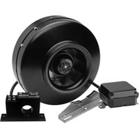


- SENSOR IN1
- PROGRAMACIÓN
- INTRODUCTION
- SAFETY REGULATIONS AND "CE" MARKING
- GENERAL INSTRUCTIONS
- DESCRIPTION
- LOCATIONS
- IMPORTANT
- WIRING DIAGRAM AND INTERNAL BOARD
- OPERATION WITHOUT PROSYS ECOWATT CONSOLE
- OPERATION WITH PROSYS ECOWATT ACCESSORY CONSOLE
- INSTALLATION
- INDIVIDUAL CONTROL WIRING DIAGRAM
- MULTIPLE CONTROL WIRING DIAGRAM
- TO CHANGE THE FAN NUMBER SHOULD FOLLOW THESE STEPS
- USING THE CONSOLE
- GENERAL PARAMETERS
- STARTING THE SYSTEM
- UNIT CONFIGURATION VIA CONSOLE
- CHANGE SET POINT
- CHANGE OPERATION MODE
- OPERATION PI PRESSURE/COP MODE
- DIGITAL INPUT
- OPERATION PI VOLUME/CAV MODE
- OPERATION PROPORTIONAL/VAV MODE
- MIN/MAX OPERATION MODE
- LOGIC
- OPERATION WITH TIMER RTC ECOWATT ACCESSORY AND PROSYS ECOWATT CONSOLE ACCESSORY
- PROGRAMMING
- SUMMARY TABLE SETTING VALUES
- MODBUS COMMUNICATION SYSTEM INTEGRATION
- BASIC FEATURES OF MODBUS-RTU CONTROL
- MODBUS MEMORY MAP
- MAINTENANCE
- PUTTING OUT OF SERVICE AND RECYCLING
- SOMMAIRE
- GÉNÉRALITÉS
- NORMES DE SECURITES ET MARQUAGE "CE
- NORMES GENERALES
- EMPLACEMENTS
- FONCTIONNEMENT SANS CONSOLE PROSYS ECOWATT
- FONCTIONNEMENT AVEC ACCESSOIRE CONSOLE PROSYS ECOWATT
- SCHÉMA DE BRANCHEMENT CONTRÔLE MULTIPLE
- UTILISATION DE LA CONSOLE
- PARAMÈTRES GÉNÉRAUX
- MISE EN MARCHE DU SYSTÈME
- CONFIGURATION DES ÉQUIPEMENTS PAR LA CONSOLE
- CHANGEMENT DE CONSIGNE
- CHANGEMENT DE MODE DE FONCTIONNEMENT
- FONCTIONNEMENT MODE PI PRESSION/COP
- ENTRÉE NUMÉRIQUE
- FONCTIONNEMENT MODE PI DÉBIT /CAV
- CONSIGNE
- FONCTIONNEMENT MODE PROPORTIONNEL / VAV
- CAPTEUR IN1
- FONCTIONNEMENT MODE MIN-MAX
- LOGIQUE
- ENTRÉE
- FONCTIONNEMENT AVEC ACCESSOIRE DE PROGRAMMATION HORAIRE TIMER RTC ECOWATT AVEC L'ACCESSOIRE CONSOLE PROSYS ECOWATT
- PROGRAMMATION
- TABLEAU RÉSUMÉ VALEURS DE RÉGLAGE
- INTÉGRATION DANS LE SYSTÈME DE COMMUNICATION MODBUS
- CARACTÉRISTIQUES DE BASE DU CONTRÔLE MODBUS-RTU
- PLAN DE MÉMOIRE MODBUS
- MISE HORS SERVICE ET RECYCLAGE
- S&P SISTEMAS DE VENTILACIÓN, S.L.U
Brand : Soler & Palau
Model : CTB ECOWATT PLUS
Category : Fan