
BEAS - Electronic control module Soler & Palau - Free user manual and instructions
Find the device manual for free BEAS Soler & Palau in PDF.
| Product type | Electronic signal adaptation control module |
| Brand | Soler & Palau |
| Model | BEAS |
| Dimensions (L × H × D) | 175 × 130 × 80 mm |
| Power supply | 24 V 50 Hz |
| Power consumption | 1.5 W |
| Protection rating | IP55 |
| Electrical insulation class | 2 |
| Operating temperature | -10 °C to +50 °C |
| Max relative humidity | 95% without condensation |
| Analog inputs | Current 0-20 mA or voltage 0-10 V on terminal J3 |
| Dry contact input | Potential-free contact on terminal J7 |
| Analog output | Voltage 0-10 V on terminal J4 |
| Relay output | Potential-free changeover contact on terminal J1, switching capacity 10 A / 250 Vac (cos φ = 0.6) or 16 A / 250 Vac (cos φ = 1) |
| Auxiliary 24 V output | On terminal J4 (between GND and 24 V): 100 mA max; on terminal J3 (between GND and +24 V): 120 mA max |
| Settings | Emin, Emax, Smin, Smax, relay threshold (via trimmers on J8) |
| Analog output forcing | Via switches S1.2 and S1.3 (Smin, Smax, auto) |
| LED indication | Flashes in case of illogical setting (Emax < Emin or Smax < Smin) |
| Connection capacity | Conductors 1 to 2.5 mm² (stranded with ferrule or solid) |
| Maintenance | No maintenance required |
| Installation | By a professional electrician, in accordance with standard NF C 15-100 |
Frequently Asked Questions - BEAS Soler & Palau
User questions about BEAS Soler & Palau
0 question about this device. Answer the ones you know or ask your own.
Ask a new question about this device
Download the instructions for your Electronic control module in PDF format for free! Find your manual BEAS - Soler & Palau and take your electronic device back in hand. On this page are published all the documents necessary for the use of your device. BEAS by Soler & Palau.
USER MANUAL BEAS Soler & Palau
BEAS Electronic Signal Adapter Unit
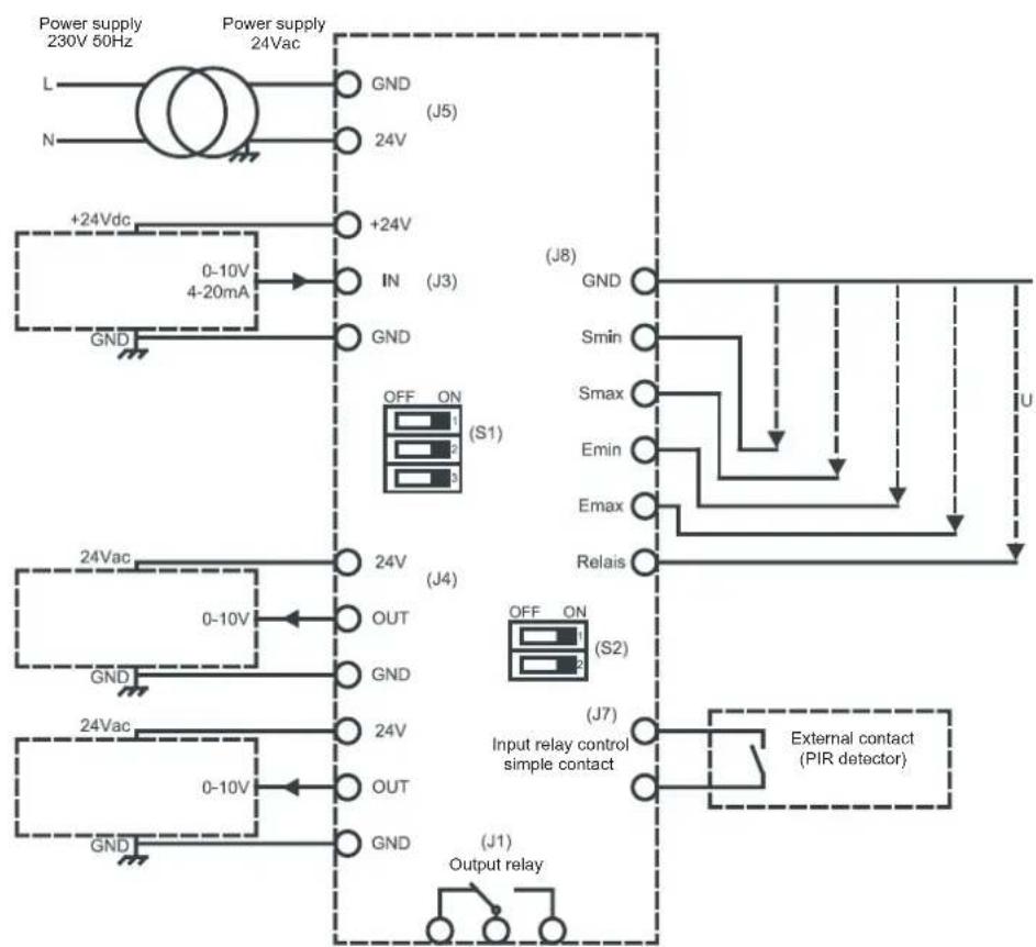
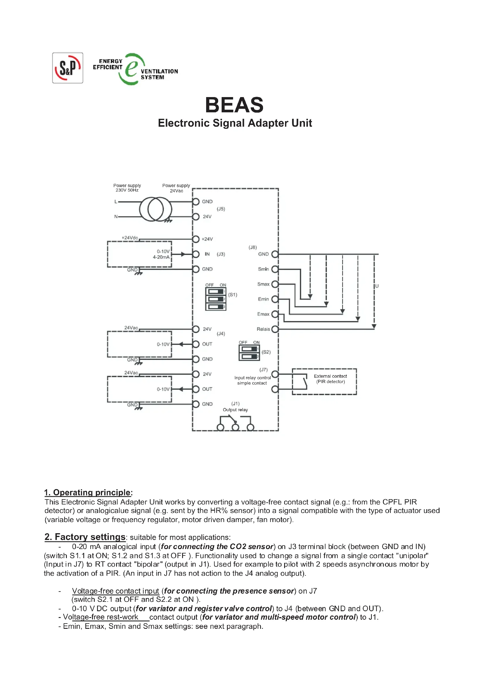
1. Operating principle:
This Electronic Signal Adapter Unit works by converting a voltage-free contact signal (e.g.: from the CPFL PIR detector) or analogicalue signal (e.g. sent by the HR% sensor) into a signal compatible with the type of actuator used (variable voltage or frequency regulator, motor driven damper, fan motor).
2. Factory settings: suitable for most applications:
- 0-20 mA analogical input (for connecting the CO2 sensor) on J3 terminal block (between GND and IN) (switch S1.1 at ON; S1.2 and S1.3 at OFF). Functionality used to change a signal from a single contact "unipolar" (Input in J7) to RT contact "bipolar" (output in J1). Used for example to pilot with 2 speeds asynchronous motor by the activation of a PIR. (An input in J7 has not action to the J4 analog output).
Voltage-free contact input (for connecting the presence sensor) on J7 (switch S2.1 at OFF and S2.2 at ON).
0-10 VDC output (for variator and register valve control) to J4 (between GND and OUT).
- Voltage-free rest-work contact output (for variator and multi-speed motor control) to J1.
- Emin, Emin, Smin and Smax settings: see next paragraph.
3. Adapting the unit for other uses:
3.1 Connecting a 0-10 V CD analogical input to J3 (between GND and IN):
Set switch S1.1 to OFF; set switches S1.2 and S1.3 to OFF).
3.2 Settings for the analogical input / analogical output transfer function:
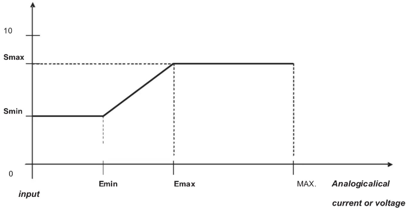
Voltage output (V DC)
a) Range of possible settings for analogical input:
If signal voltage: 0V≤ Emin < 10V DC
Emin < Emax ≤ 10 V DC
If signal current: 0mA≤ Emin < 20~mA
Emin < Emax ≤ 20 mA
Factory settings: Emin = 7.2 mA; Emax = 14.4 mA
These settings are for connecting a SCO2 CO2 sensor.
To change the factory settings:
Example: Emin:
Connect a voltmeter (AC voltage) between GND and Emin on terminal J8:
Factory setting = 1.8V
Using a flat-headed screwdriver, rotate the trimmer marked " Emin " (e.g. until the voltmeter indicates 2V)
The value matches Emin/4 if analogical input = current
(Example = a reading of 2 V means Emin = 2 x 4 = 8 mA; i.e. as long as the IN input is lower than 8 mA the output is Smin)
The reading is Emin/2 if input = voltage
(Example = a reading of 2 V means Emin = 2 x 2 = 4 V; i.e. as long as the IN input is lower than 4 V the output is Smin)
For Emax: follow the same procedure with GND and Emax by rotating the Emax trimmer
(Example = a reading of 4 V means Emax = 4 x 4 = 16 mA; i.e. when input IN is higher than 16 mA the output is Smax)
Note: Rotating the trimmer anti-clockwise increases the voltage.
b) Range of possible settings for the analogical output:
0V≤ Smin < 10VDC
Smin < Smax ≤ 10 V DC
To change the factory settings:
For Smin = rotate the Smin trimmer (measure between GND and Smin on the J8 terminal block and multiply the obtained value by 2; e.g. if the reading = 2 V this means Smin is really 4 V).
For Smax = rotate the Smax trimmer (measure between GND and Smax).
Note:
To make it easier to adjust the aeraulic settings of the installation, the analogical output can be forced using switches S1.2 and S1.3:
| S1.2 S1.3 Analogical output | (on connector J4, between GND and OUT) |
| OFF OFF Automatic (non-adjustable) | |
| ON OFF Forced to Smax | |
| OFF ON Forced to Smin | |
| ON ON Automatic (non-adjustable) |
Logically illegal settings ( = if Emax < Emin or Smax < Smin) cause an LED indicator to flash.
| S2.1 S2.2 | Output relay | (on connector J1) |
| OFF OFF | Inactive output relay | |
| ON OFF | Active | output relay with analogical input (J3) |
| OFF ON | Active | output relay with external contact (J7) |
| ON | ON | Active output relay with analogical input (J3) |
3.1 Setting the output relay trigger threshold (terminal block J1):
For the relay contact to switch when the analogical input reaches a certain value, switches S2.1 and S2.2 should be set to ON.
Factory setting: for analogical input = 14.4mA
To change the factory settings:
Connect a voltmeter (AC voltage) between GND and Relay on terminal block J8:
Using a flat-headed screwdriver, rotate the trimmer marked "Relay" (e.g. until the voltmeter indicates 2V)
The value matches Relay/4 if analogical input = current
(Example = a reading of 2 V means the relay will trip on an analogical input value of = 2 × 4 = 8 mA)
The reading is Relay/2 if input = voltage
(Example = a reading of 2 V means the relay will trip on an analogical input value of = 2 × 2 = 4V )
OTHER REMARKS:
Location:
Mount in an equipment room, suspended ceiling or attic.
Dimensions (L× H× D) in mm: 175× 130× 80
Power supply (J5): 24 V 50 Hz.
Consumption: 1.5 W.
Connection capacity of unpluggable connectors supplied:
For flexible multistrand conductors with end terminals or rigid conductors of section 1 to 2.5mm^2
Electrical properties of built-in relay (J1):
Breaking capacity of contact = 10A at 250VAC ( fi = 0.6) / 16A at 250VAC ( fi = 1) .
Output 24 V 50 Hz (J4 between GND and 24 V): Maximum available current: 100 mA
Output +24 V (J3 between GND and +24 V): Maximum available current: 120 mA
Output 0-10 V (J4 between GND and OUT): Maximum available current: 10 mA
Plastic enclosure with electrical insulation rating: 2.
IP protection rating: IP55.
Operating environment:
Temperature: -10 °C to +50 °C.
. Relative humidity: max. 95% without condensation.
Maintenance: none required.
Standard compliance: CE conformity certificate available on request.
Electrical connections should conform to personal safety standards NF C 15-100.
IMPORTANT! This appliance should only be installed. configured and serviced by a professional electrician working in accordance with the rules of good professional conduct, installation guidelines and applicable safety regulations.
Before powering up the appliance, make sure the supply voltage matches the voltage indicated on the product: connecting the appliance to an incorrect voltage may destroy it.
Disconnect power before servicing the appliance. Do not touch live parts. Danger of death! Electrical connections which do not conform to the diagrams given in the notice and/or applicable installation requirements shall render our guarantee void.

- BEAS Electronic Signal Adapter Unit
- Operating principle:
- Factory settings: suitable for most applications:
- Adapting the unit for other uses:
- Connecting a 0-10 V CD analogical input to J3 (between GND and IN):
- Settings for the analogical input / analogical output transfer function:
- a) Range of possible settings for analogical input:
- Example: Emin:
- b) Range of possible settings for the analogical output:
- Setting the output relay trigger threshold (terminal block J1):
- OTHER REMARKS:
- Operating environment:
Brand : Soler & Palau
Model : BEAS
Category : Electronic control module