
Ergo Lift 650 - Lift bridge GYS - Free user manual and instructions
Find the device manual for free Ergo Lift 650 GYS in PDF.

| Product Type | Mobile lift for passenger vehicles |
| Brand and model | GYS Ergo Lift 650 |
| Maximum load capacity | 2000 kg (CMU) |
| Power supply | 230 V AC, 50 Hz, single-phase (16A CEE7/7 plug) |
| Motor power | 0.75 kW |
| Oil tank capacity | 4 L (hydraulic oil viscosity 32 CST) |
| Lifting time | Approximately 45 seconds at full load |
| Noise level | < 70 dB(A) |
| Protection rating | IP54 |
| Net weight (without packaging) | 247 kg |
| Weight with packaging | 282 kg |
| Product dimensions with packaging | L 226 cm × W 108 cm × H 69 cm |
| Overall dimensions (lift alone) | L 242.4 cm × W 195.5 cm × H 130 cm (arms folded) |
| Maximum lifting height | Approximately 55 cm (from floor to crossbeam) |
| Operating temperature range | 5 °C to 40 °C |
| Maximum floor slope | 3° |
| Recommended hydraulic oil type | IKV-TRIBOLINE HLQ HM-32 (ref. 062160) |
| Controls | Wired remote control with Up/Down buttons and emergency stop |
| Safety | Emergency stop, limit switch, pressure relief valve (140 bar), audible alarm when lowering, arm locking notches |
| Maintenance | Monthly lubrication of joints (20 points), visual check before each use, oil change every 5 years or depending on usage |
| Warranty | 2 years (parts and labor) |
Frequently Asked Questions - Ergo Lift 650 GYS
User questions about Ergo Lift 650 GYS
0 question about this device. Answer the ones you know or ask your own.
Ask a new question about this device
Download the instructions for your Lift bridge in PDF format for free! Find your manual Ergo Lift 650 - GYS and take your electronic device back in hand. On this page are published all the documents necessary for the use of your device. Ergo Lift 650 by GYS.
USER MANUAL Ergo Lift 650 GYS
natural_image
Technical line drawing of a mechanical lifting device with two views: top shows a vertical support mechanism, bottom shows a horizontal frame assembly (no text or symbols)
Operation and maintenance manual p. 24-46
CONTRÔLE DE SÉCURITÉ ET DE FONCTIONNEMENT
flowchart
graph TD
    A["1: Robot with red directional arrows on platform"] --> B["2: Robot with red directional arrows on platform"]
    B --> C["3: Robot with green arrow and recycling symbol"]
    style A fill:#f9f,stroke:#333
    style B fill:#ccf,stroke:#333
    style C fill:#cfc,stroke:#333
natural_image
Two red car side-by-side diagrams showing parking or garage system, with a lock icon and thumbs-up indicator (no text or symbols on the cars themselves)natural_image
Mechanical assembly diagram showing a red and gray component with a labeled 'mini' arrow (no text or symbols beyond label)text_image
(2) -/+ (1)ANOMALIES, CAUSES, REMEDES
CONDITIONS DE GARANTIE
text_image
Technical diagram of a mechanical device with labeled parts 1 and 2, showing components like a vertical rod and motor assembly.text_image
QR code image containing encoded data, no visible human-readable text20.07.0 56817.0 00001
text_image
Technical diagram of a mechanical assembly with numbered components, likely for assembly or maintenance purposes.INDICATIONS SUR LE PRODUIT
text_image
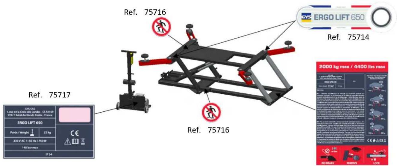
Ref. 75716 Ref. 75714 Ref. 75717 Ref. 75716 2000 kg max / 4400 lbs max GVS 545 1. rue de la Crude des Landes - CS 54159 S39+1 Saint-Berthbevis Cedex - France ERGO LIFT 650 Poids / Weight 32 kg 230V AC 1-50 Hz / 750W 140 bar max IP 54 ERGO LIFT 650 No Brake Remove LockRef. 75715
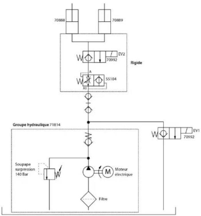
CIRCUIT HYDRAULIQUE
flowchart
graph TD
    A["70888"] --> B["Rigide"]
    C["70889"] --> B
    D["70992"] --> B
    E["55104"] --> B
    F["AV2"] --> B
    G["AV1"] --> H["Groupe hydraulique 71814"]
    I["Soupape surpression 140 Bar"] --> J["Moteur électrique"]
    K["Filtre"] --> J
    J --> L["EV1"]
    style A fill:#f9f,stroke:#333
    style C fill:#f9f,stroke:#333
    style D fill:#f9f,stroke:#333
    style E fill:#f9f,stroke:#333
    style F fill:#f9f,stroke:#333
    style G fill:#f9f,stroke:#333
    style I fill:#ccf,stroke:#333
    style K fill:#ccf,stroke:#333
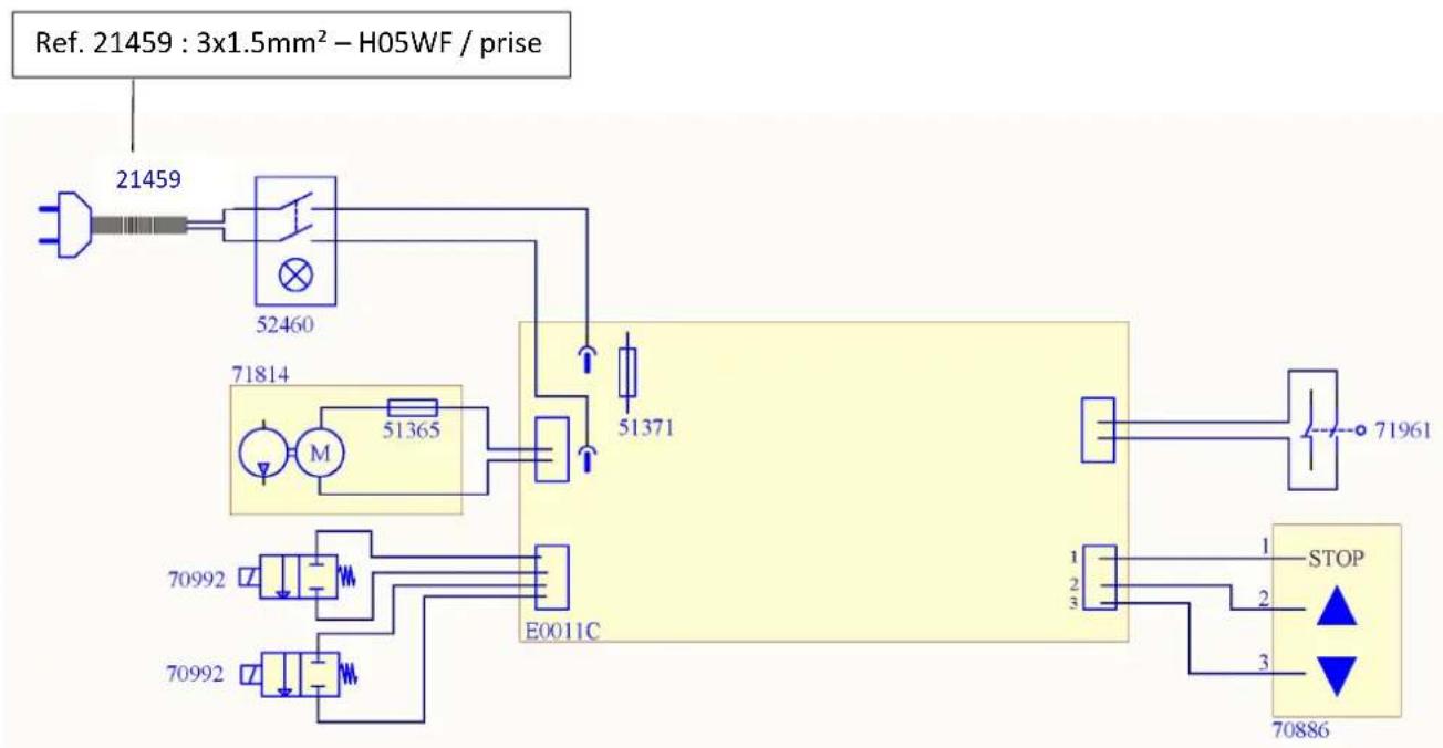
CIRCUIT ELECTRIQUE
flowchart
graph TD
    A["21459"] --> B["52460"]
    B --> C["71814"]
    C --> D["M"]
    D --> E["51365"]
    E --> F["E0011C"]
    F --> G["STOP"]
    G --> H["70886"]
    I["Ref. 21459 : 3x1.5mm² – H05WF / prise"] --> B
    J["71961"] --> K["STOP"]
    L["70992"] --> M["70992"]
    N["70886"] --> O["STOP"]
    P["71814"] --> Q["70992"]
    R["70992"] --> S["70992"]
C O N T R O L E R E G U L I
Safety and functional check
In order to guarantee that your ERGO LIFT 650 lift has been manufactured in strict compliance with safety standards, here are the results of the tests that your product has been subjected to before shipment (please always keep this manual provided when you purchased the equipment).
The following elements are present:
■ Technical notice board on the back of the hydraulic power station.
- Serial numbers on the technical notice board and on the lift.
■ Instructions for use
■ Maximum authorised load capacity of 2,000 kg.
■ Raise "↑" and lower "↓" on the cable control.
- CE identification on the lift.
Controlled operation and safety:
Pressure relief valve set at 140 bar max.
Verify:
■ No-load function test over a complete cycle
■ Operation of the emergency stop button
■ Controls automatically return to initial position
- No damage to the cylinders, the power supply cable, and the wired remote control cable
- Tight fastening of all bearing screws
- Condition of the hydraulic hose (tightness and watertightness of all connections)
- Operation with the maximum load over a complete cycle
- Checking the function of the safety device in the event of a hydraulic hose rupture under load.
Serial No
Find the serial number on the nameplate page 43.
For more information on reading the serial number see page 41.
EC Certificate of Conformity
You can download the certificate of conformity from our website: www.gys.fr.
heading: PRODUCT_CARROSSERIE_CARROSSERIE_LEVAGE
Thank you for choosing GYS In order to obtain maximum satisfaction from your ERGO LIFT 650 and for your safety, please read these operating instructions carefully before first use and keep them in a safe place for future reference.
BACKGROUND INFORMATION
These operating instructions contain important information for installation in order to ensure proper commissioning and operational safety of the ERGO LIFT. Complying with the documentation reduces risks and extends the life of the product. This manual contains a form to certify regular security checks. Use the "Regular Safety Inspection" form and the "Maintenance Log" to archive the inspections (It is advisable to make a copy of the forms before filling them in for the first time).
Installation and control:
Safety work and safety checks are reserved exclusively for specially trained persons. These persons are referred to in this documentation as experts and/or authorised persons.
LIMITATIONS OF LIABILITY
The ERGO LIFT is a mobile lift designed in compliance with standards. All data and advice in this manual have been collected in accordance with its applicable standards and regulations and our extensive knowledge and experience.
The manufacturer cannot be held responsible in case of material and physical damage that could lead to death by:

• Non-observance of the instructions for use
- Improper or dangerous use
- Employment of unskilled persons
- Unauthorized processing on the ERGO LIFT
• Insufficient maintenance
INTENDED INTENDED USE
The ERGO LIFT is designed for the repair of passenger vehicles. It allows vehicles to be lifted safely. Maximum authorised load capacity of 2,000 kg.
Intended use of the ERGO LIFT includes familiarisation with these operating instructions in their entirety and observance of all the instructions contained herein, with particular reference to the safety instructions. The ERGO LIFT must be used and handled in accordance with these operating instructions.
A safety perimeter must be defined in which no one must be present during the lifting operation (minimum 2m around the vehicle to allow escape if necessary).
The lifting of persons or other objects is not allowed. No one must be inside the vehicle to be lifted. It is forbidden for persons to climb onto the load or the load support device when these are in the raised position.
The ERGO LIFT must be used inside a work room and protected from bad weather (wind, rain and negative temperature).
The operating temperature range is between 5^ C and 40^ C maximum. In case of prolonged storage in a place where the temperature is below 0^ C, allow at least 12 hours before use by storing it in the workplace.
Do not use in excessively humid conditions. If water is splashed directly onto the lift, use a clean cloth to wipe it off.
This equipment is delivered with a 16 A CEE7/7 type plug and must only be used on a single-phase 230 V (50Hz) electrical installation.
Never lift loads on sloping ground ( >3^ ). The floor must be flat and strong enough to prevent the ERGO LIFT from sinking under the weight of the load ( 35kg/cm^2 ). Under no circumstances should the ERGO Lift be placed on an inspection hatch on the floor.
It is forbidden to use the ERGO LIFT on a boat/vessel (stability problem).
Thoroughly clean the supporting surface of the vehicle and the rubber pads of the ERGO LIFT before each use.
Remove all grease and oil stains that could cause the vehicle to slip.
Work underneath the vehicle is not permitted.
Vehicles should only be lifted at the lifting points recommended by the car manufacturers. Make sure that the ERGO LIFT does not come into contact with areas close to the airbag activation sensors during and after the lift.
Do not place the rubber pads on an area with plastic trim.
Take care of the electrical cables as well as the hydraulic hose.
It is advisable to avoid driving on the hose connecting the lift to the hydraulic unit. When this is not possible, parking on it should be avoided.
In the event of a violent impact on the load-bearing and/or structural elements of the ERGO LIFT, it is imperative to take the product out of service and contact your dealer or the manufacturer in order to assess the damage before putting it back into service.
In case of doubt about the strength of the vehicle structure (presence of rust) - Do not lift the vehicle.
Enforce safety and risk prevention standards in the country's workplaces (the country's labour code). In addition, this also includes the obligation to carry out all inspection and maintenance work at regular intervals.
In the event of improper use of the lift, the operational safety of the ERGO LIFT is not guaranteed.
Damage to persons and property, also on vehicles, caused by improper use of the device is in no way the responsibility of the manufacturer, but of the operator handling the ERGO LIFT.
ERGO LIFT must not be used in a potentially explosive atmosphere and it is not recommended to work next to a heat source. The ERGO LIFT has not been designed for use in a spray booth.
It is forbidden to use spare parts other than original parts certified by the manufacturer.
Also ensure that the wired control cannot be tampered with by unauthorised persons while you are working around the vehicle.
PACKAGING AND UNLOADING
The ERGO LIFT user and maintenance manual is included in the packaging of the hydraulic unit. On delivery, check for external transport damage. In case of visible damage, leave the goods and packaging as they are. Do not use the goods and contact your dealer directly. Failing this, a reservation must be made to the carrier. Under no circumstances can GYS be held responsible.
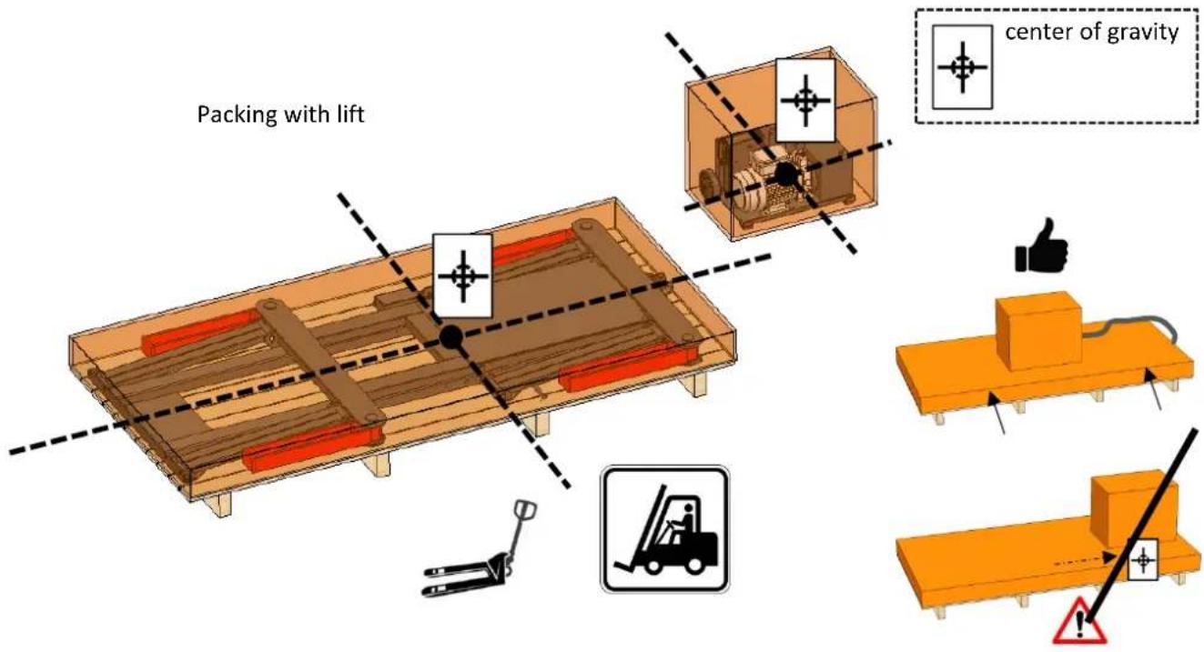
Unloading can be done with a forklift or hand pallet truck as soon as the pallet is placed on the floor. Wear gloves and safety shoes.
text_image
Packing with lift center of gravity1- Determine an area with sufficient space and good lighting.
2- Unpack and place the hydraulic power unit on the ground, aligning the beam so that it is not folded on itself and/or twisted.
3- Remove the cardboard cover on the lift and carry out a visual inspection to check that nothing is damaged and that there are no visible oil leaks at the connections.
***There may be "traces of oil" prior to first use that are related to the manufacturing process. Wipe with a clean, dry cloth if necessary ***
4- Connect the hydraulic group to the mains and press the "ON" button on the side of the hydraulic group. The button lights up to indicate that the hydraulic power unit is energised.
5- Press the up button or "↑" on the remote control until the lift reaches the very top (no need to top up the oil, the unit is ready for use). A double beep will indicate that the maximum position has been reached. The motor should stop automatically and it should no longer be possible to lift. If this is not the case, please refer to ANOMALIES, CAUSES, REMEDIES on page 37.
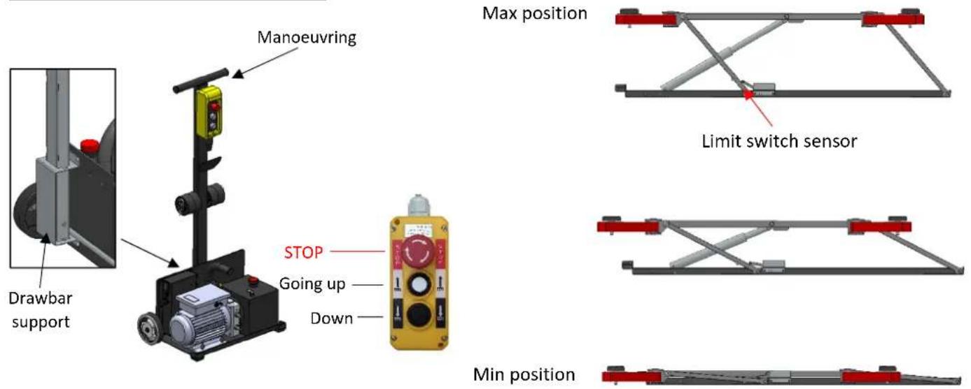
6- Retrieve and assemble the manoeuvring drawbar and attach it to the hydraulic unit to be able to move it more easily.
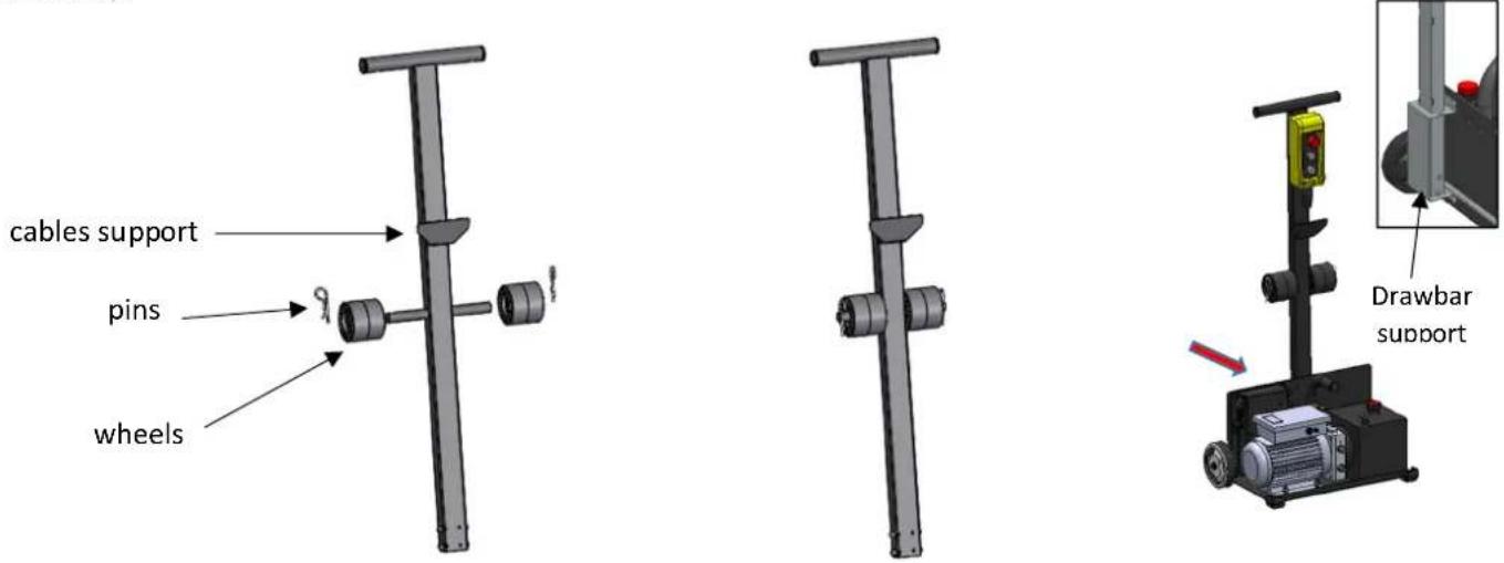
text_image
cables support pins wheels Drawbar support7- Remove the 4 screws from the lift that fixes it to the pallet.
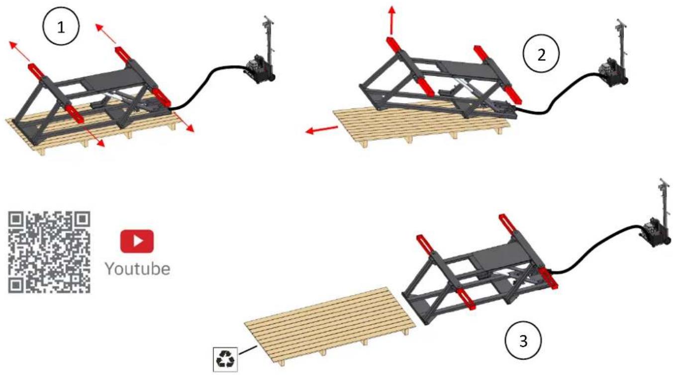
8- With the help of a strap and a firmly attached hoist (weight to be lifted 130kg max.) lift the table by the lightest side of the lift (front of the lift) then remove the pallet under the table. Be careful not to injure yourself and don't hesitate to be in a group to carry out the manoeuvre in complete safety (3 people recommended). Never get under the hoist or put yourself in a dangerous situation).
If you do not have a hoist, you can remove the lift from the pallet manually. Position the 4 arms of the table to have as many holds as possible as shown in the picture below. Lift the lighter side first and gradually remove the pallet from underneath.
flowchart
graph TD
    A["1: Robot arm with red arrows indicating motion"] --> B["2: Robot arm with red arrows indicating motion"]
    B --> C["3: Robot arm with green arrow indicating direction"]
    C --> D["4: Robot arm with blue arrow indicating direction"]
    style A fill:#f9f,stroke:#333
    style B fill:#ccf,stroke:#333
    style C fill:#cfc,stroke:#333
    style D fill:#fcc,stroke:#333
Packages should not be placed in a bin but in a recycling bin.
INDIVIDUAL PROTECTION
The operator must be equipped in accordance with the occupational risk prevention standards applicable in his/her country and must adopt all necessary measures to maintain safety at his/her workstation. During manoeuvres, the operator must ensure his own safety and that of the people and objects around him. The operator must take into consideration all the recommendations quoted in this manual.

Hydraulic fluid is dangerous if splashed in the eyes or if it comes into contact with blood. In this case, contact your doctor immediately. Never reach over your hand to check for a hydraulic leak: risk of cut and contamination in the bloodstream.
START UP
Make sure you have the necessary protection: safety shoes and gloves.
Step 1: Place the ERGO LIFT on the floor and position the hydraulic unit 3 metres from the lift, making sure that the beam is not twisted and bent.
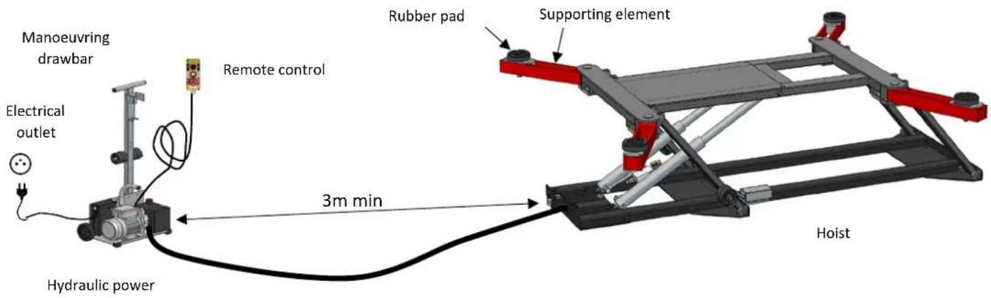
text_image
Manoeuvring drawbar Electrical outlet Hydraulic power Remote control Rubber pad Supporting element 3m min HoistStep 2: Connect the hydraulic unit to an electrical outlet and set the button to "ON".
Step 3: Place the 4 runners on the load-bearing elements.
It is possible to adjust the runners in height (1) and all along the arm (2).
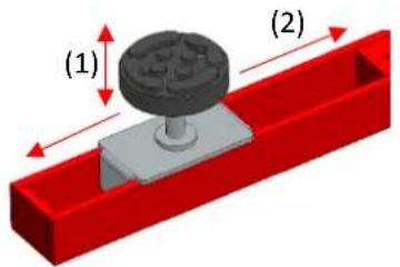
text_image
(1) (2)
Each skate is equipped with a solidly attached mechanical stop - never use a skate without a stop.
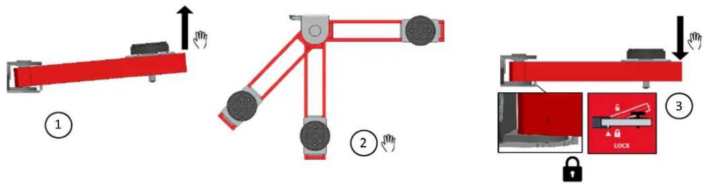
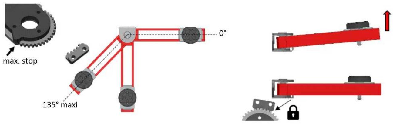
Step 4: It is possible to move the supporting elements (= arms) of the lift at an angle. To do this, lift the end of the arm in order to release the movement, position it as desired and release it. After each repositioning, check that the arm is securely in place and locked into a safety catch by making a left-to-right movement. Never perform this operation with your foot. Always make this adjustment with your hand to carry out the necessary checks of the correct positioning of each load-bearing element.
text_image
Diagram illustrating three different robotic arm manipulator mechanisms with labeled parts and directional arrowsStep 5: Using the remote control:
text_image
Manoeuvring Drawbar support STOP Going up Down Max position Limit switch sensor Min positionPress the up button or "↑" to raise the lift. As long as the button is held down, the lift will rise until a double beep sounds (end position reached by the sensor). Automatically when the button is released, the lift stops.
Press the down button or "↓" to lower the lift. A beep for 2 seconds preceded by the descent of the table will be heard each time the button is pressed and an audible signal will be emitted throughout the descent to warn people around the manoeuvre. Automatically when the button is released, the lift stops.
In case of an emergency, it is possible to stop the ascent and descent of the lift by pressing the red emergency stop button. To disengage it, pull the button and at the same time make a quarter turn.
Step 6: Moving the lift
h- The lift must be raised about 15 centimetres from the ground.
i- Insert the 2 wheels and the safety pins.
j- Lower the lift to the floor.
k- Fold the 4 arms towards the inside of the lift.
I- Move the group close to the lift and place it on the lift as shown in the figure below.
m- Insert the operating tiller at the level of the slot on the lift.
n- Press and push lightly on the tiller to move the lift wherever you want on level ground with no slope (<3°).
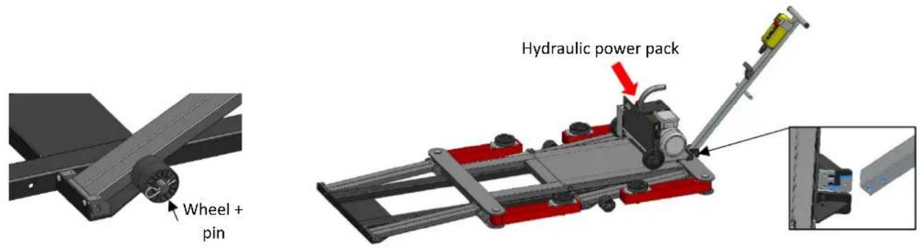
text_image
Wheel + pin Hydraulic power packOnce the area has been determined, place the lift and carry out the reverse manoeuvre without forgetting to remove the 2 wheels and the pins and store them on the support at the level of the manoeuvring tiller.
OPERATING INSTRUCTIONS
To achieve optimum safety, it is recommended to define an area in which other objects or walls will be at a certain distance (2m minimum). All ascent and descent manoeuvres must be carried out with the best possible attention on the part of the operator. Within the defined area, it is forbidden for people to park when the lift is in motion. In order to guarantee the operator's safety, the control box must be located at a distance that allows an escape route in case of emergency. It must be taken into account that the vehicle will move 30cm towards the front of the lift when going up and down.
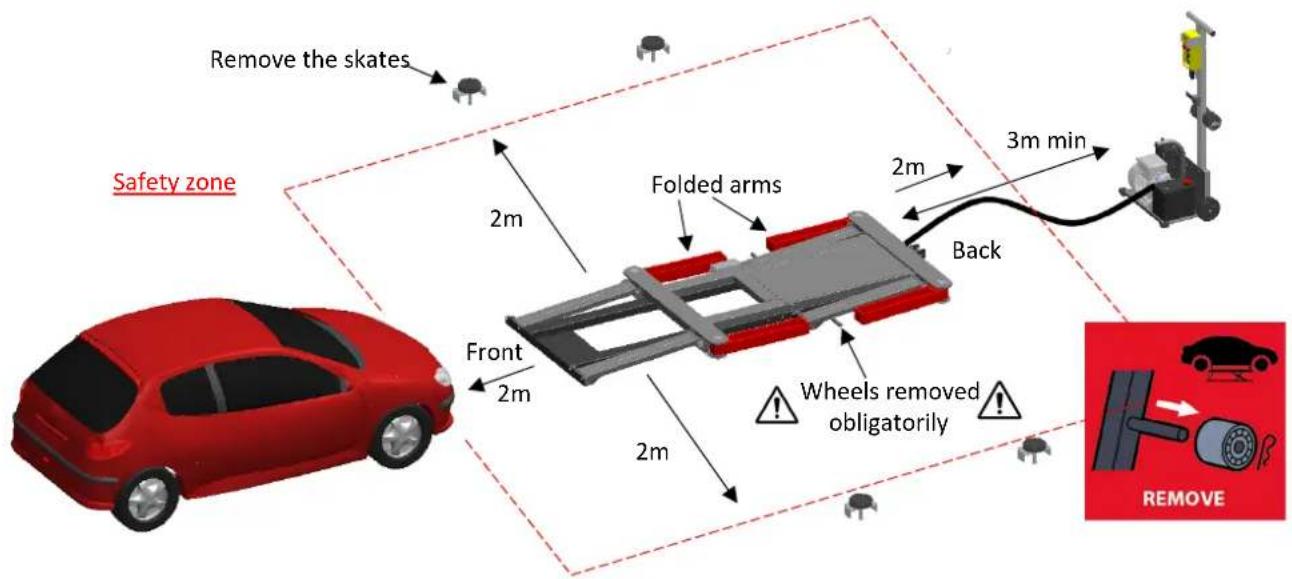
text_image
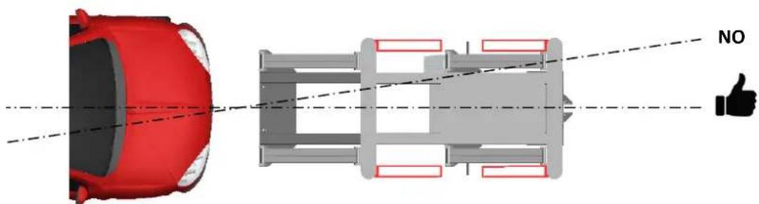
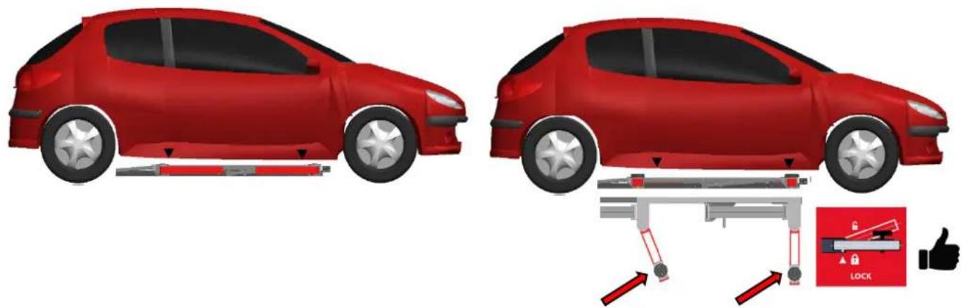
Remove the skates Safety zone 2m Folded arms 2m 3m min Back Front 2m 2m Wheels removed obligatorily REMOVEMake sure that the vehicle is as centred as possible on the longitudinal axis of the lift.
natural_image
Diagram of a car showing front and side views with no visible text or symbolsThen spread the arms completely apart and put the rubber pads on them. Position the skids below the grip points provided by the car manufacturers.
natural_image
Two red car side-by-side diagrams showing parking or garage system, with a lock icon and thumbs-up indicator (no text or symbols on the diagram itself)Once the support arm has been correctly positioned, check that it is correctly in place and locked by simply moving it from right to left.
Lift the vehicle a short distance (all 4 wheels should be about 10 to 15cm off the ground) and check that the skids are correctly positioned and that the vehicle is stable. Once this check has been carried out, lift the vehicle to the desired height and store the remote control.
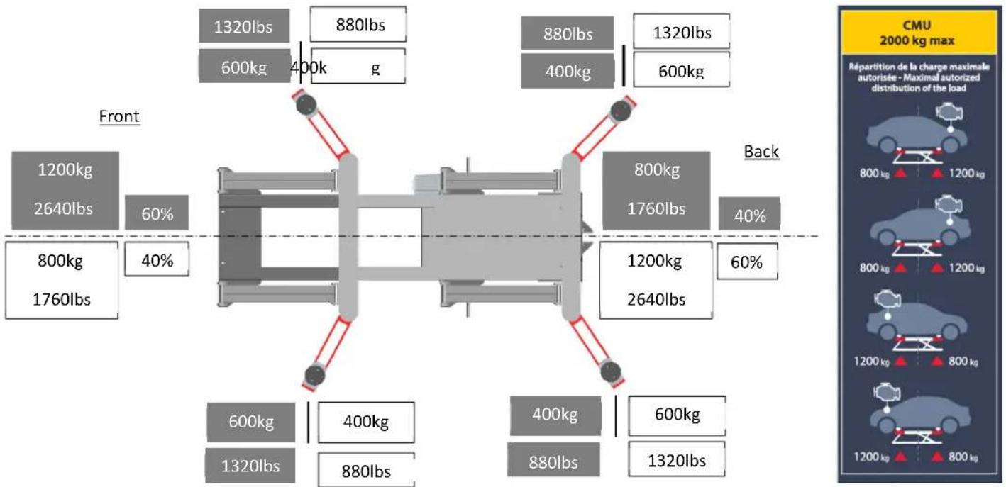
Maximum loading principle of the lift :
This self-stable lift has been dimensioned to accept a maximum working load (M.W.L.) of 2000kg /4400lbs as shown in the figures below and regardless of the position of the arms (open angle or fully closed). This means that it is necessary to respect a loading of 60% of the mass on the front of the lift and 40% on the back of the lift and vice versa. It is designed to accept a reversible load.
By respecting the alignment of the lift with the longitudinal axis of the vehicle and by positioning the rubber pads below the gripping points identified by the car manufacturers, you will respect this principle and be able to lift the load safely. This information is to be found on the lift so that the user does not exceed the maximum load depending on the situation (position of the engine in the vehicle according to the direction of the lift).
other
| Location | Total Load (lbs) | Percentage (%) | | :--- | :--- | :--- | | Front | 1320 | 600 | | Front | 880 | 400 | | Front | 880 | 400 | | Front | 1320 | 600 | | Front | 1200 | 2640 | | Front | 800 | 1760 | | Front | 400 | 60 | | Back | 800 | 1760 | | Back | 1200 | 2640 | | Back | 40 | 60 | | Back | 600 | 1320 | | Back | 400 | 880 | | Back | 880 | 880 | | Back | 600 | 1320 | CMU 2000 kg max Répartition de la charge maximale autorisée - Maximal autorized distribution of the load
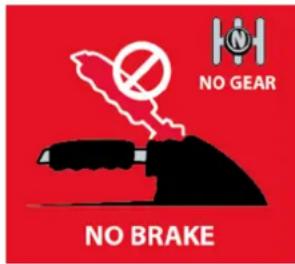
Before lifting a vehicle, make sure the handbrake is released and the vehicle is left in neutral. The wheels when taking off from the ground need to be free as when descending. Otherwise, there is a risk that the load will slip on the rubber pads and lead to a dangerous and unstable situation. In some cases a displacement of the lift at ground level can be observed.
text_image
NO GEAR NO BRAKECONTROLS AND MAINTENANCE
Inspections and maintenance work must be carried out by authorised personnel at the maintenance intervals specified in this manual. In order to guarantee a long service life and proper use of the ERGO LIFT, the following points must be observed.
- Switch off the power supply before carrying out any maintenance.
- Only original spare parts must be used "Spare parts" page 41.
- The recommended maintenance intervals must be adhered to "Maintenance table" on page 34 and recorded on pages 45 and 46.
- For maintenance work that is not shown or indicated in the operating instructions, contact your distributor and/or the manufacturer.

natural_image
Mechanical assembly diagram showing a red and gray conveyor system with a downward arrow labeled 'min' (no text or symbols on the diagram itself)Visually inspect your ERGO LIFT before each use. Do not use it if you detect damage, severe wear or hydraulic leakage.

Clean the ERGO LIFT at least once a week to remove all dust and dirt that could degrade the proper functioning of the product in the long term. Use auto cleaning cloths. Do not use any water nor flammable or corrosive liquids.
To intervene on the limit sensor and on the electrical components present on the lift (wiring harness / electrical control of the solenoid valves) raise the lift completely until it reaches the maximum position and then cut off the power supply.
MAINTENANCE TABLE
| Maintenance intervals | Task Remarks | |
| Monthly | Check, clean and lubricate all moving parts, especially the joints.Check that the locking system of the 4 load-bearing elements is working properly and that the stops are present.Check the condition of the rubber pads and clean them if necessary.Check the condition of the hydraulic hoses, the cable of the wired remote control and the power supply cable.Check the hydraulic oil levelCheck the structure visually.Carry out an unladen ascent over the full stroke of the lift.Check that the limit switch is working correctly (double beep when the lift is in the maximum position). | Refer to "Check and Lubrication Point (page 35)".Replace if necessary(Refer to the exploded view)If necessary, top up the level: Use an oil with a viscosity of 32CST (ref 062160 / canister 5L) page 36.See page 30 for a description of the procedure which describes normal behaviour and page 36 which describes the operation of the limit sensor. |
| Annual | "Regular security check" | To be carried out by an authorised person and to be completed and signed. |
| Every 5 years of service | Replace the hydraulic hose in case of heavy use and change the oil. | Replace if you notice a decrease in climb speed. A hose crushed by the passage of car wheels over the course of use may be the cause (Ref. 70887 - hydraulic hose). |
Use the "Regular Security Check" and the "Maintenance Log" forms to archive regular and annual checks.
Carry out a report on the condition of the ERGO LIFT every year and enclose it with the operating instructions.
Regular safety checks must be carried out by an authorised person. It is recommended to perform maintenance at the same time and refer to this manual for troubleshooting.
CHECK POINT AND LUBRICATION
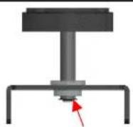
- All joints are provided with small holes for lubrication with SAE 90 type oil (fluid oil). The 20 lubrication points are listed below (1). One drop per hole is enough!
- Check the tightness of the individual screws at the joints. The lock washer must always remain flat (2).
- Check the presence of the stops on the 4 pads that prevent the pad from being completely unscrewed from its support (3).
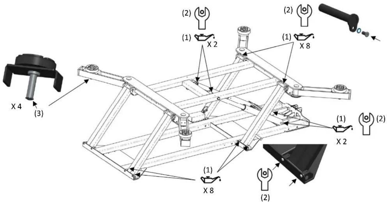
text_image
(1) X 2 (2) (1) X 8 (2) X 4 (3) (1) X 2 (1) X 8 (2)- Test each of the 4 arms and check that they can move over their full range of motion. The arm must not be able to exceed a maximum angle of 135^ . If this is not the case, the presence of the stop must be checked. At the same time, check that the arms engage in the locking catches. Otherwise, unscrew the screws of the toothed plate without forcing (the indexing plate may have moved sideways, pre unscrew each screw slightly, then all the screws so as not to damage the threads of the screws and the lift). Reposition the plate so that the notches can pass through and tighten each of the screws to 12N.m. In the event of a problem, contact Customer Service or your dealer to carry out a complete replacement of the indexing system (refer to the exploded view on page 41, replace the screws and lock washers at the same time).
text_image
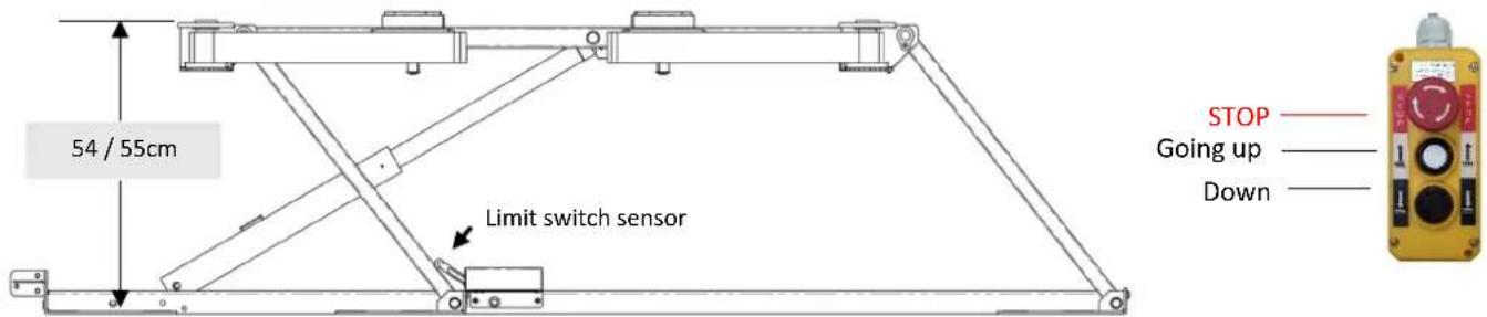
max. stop 135° maxi 0°Functional test of the limit sensor:
- Press the "Up" or "↑" button until a double beep is heard and the lift stops automatically.
text_image
54 / 55cm Limit switch sensor STOP —— Going up —— Down ——The distance from the ground to the crossbar should be between 54cm and 55cm. If the reached height is lower or higher, an adjustment of the sensor rod must be carried out. If you find that the motor does not stop automatically when the lift no longer rises, the sensor rod must be adjusted as well. After adjustment, check that the table is within the tolerances shown in the diagram above. If you still cannot find the right position, check the connections or the status of the sensor cable from the sensor to the control board. When working on the electrical circuit, always unplug the power cord and switch off the hydraulic unit.
By adjusting the length of the rod you will be able to find the right setting.
text_image
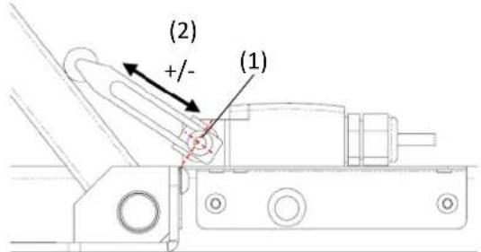
(2) +/- (1)Limit switch adjustment
1- Slightly loosen the screw (1).
2- Adjust the rod +/- (2)
3- Tighten the screw (1)
4- Check the height: 55.5 < H < 56.5
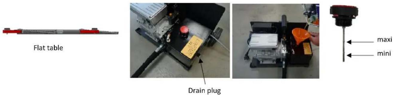
Checking the oil level:
The ERGO LIFT is supplied with sufficient oil, there is no need to add oil during start-up.
The tank can hold 4L of oil. A dipstick is used to check that the oil level is sufficient. Simply check that the level is higher than the indicator on the cap (minimum level) and do not exceed this level by more than 1cm to 2cm. Use chemical-resistant nitrile rubber protective gloves and goggles when leveling the oil.
Unless the oil is used very intensively and there is a colour change in the oil, there is no indication to replace the oil every year. We recommend replacing the oil every 5 years at the same time as the hose.
Use high performance hydraulic oil with a viscosity of 32CST (reference 062160 / type IKV-TRIBOLINE HLQ HM-32).
The table below shows the anomalies that can be observed when using the ERGO LIFT. If the problem is not listed in the table below, stop using the tool and immediately contact your dealer or the manufacturer for instructions. Take the product out of service (follow the procedure for taking out of service on page 38).
| TROUBLESHOOTING | CAUSES Solutions | |
| The lift does not move up and down with the power cord plugged in and the button set to "ON". | The "ON" button is lit orange.The red emergency stop button on the remote control is pressed. | Reset the button by doing a 1⁄4 turn. |
| The "ON" button is lit orange.Break in the wiring between the remote control and the electronic control board. | Check that when you press the "down" or "↓" button, the indicator lights on the solenoid valves come on (light = coil active). Refer to the wiring diagram to identify the wiring problem. | |
| The "ON" button is offCheck the condition of the fuse below the ON/OFF button. | Unplug the power cord. Replace the fuse with a fuse T10A-250VAC - 5x20 (ref 51365 n°50) if it is out of order. | |
| Lift goes up or down incorrectly (in jerks) | There must be air in the hydraulic system. | The circuit must be purged by going up and down until the phenomenon disappears. If it persists, contact after-sales service. |
| The lift does not go up and yet the hydraulic unit works. | The load is too heavy for the lift.Check that the vehicle still has its wheels if you return the lift to the ground. | Check the weight of the vehicle, which must not exceed the characteristics listed in the technical table (< 2T).Contact the after-sales service. |
| The lift emits a sound to identify 3 types of situations: | At the end of the stroke, a double beep indicates that the sensor is in the maximum position (switch open).When you hear a triple beep it means that you have pressed the "up" or "down" button on the remote control for too long. An automatic stop of the group is carried out after 1 minute on the way up and 1 minute 30 on the way down.When the "down" button is pressed a pause time of 2 seconds is taken and then throughout the descent anaudible warning must be heard to indicate that the lift is descending. | This indicates that the limit sensor is working properly. If the sensor malfunctions or a shock close to the area may cause the sensor to be out of adjustment, in which case refer to the limit sensor adjustment procedure on page 36.Check that there is enough oil in the tank if the product comes up.Lubricate all joints.If the problem persists, please contact the after-sales service (hydraulic pump to be replaced). |
| The lift descends very slowly without using the remote control. | Both coils are activated Each solenoid valve is equipped with manual activation in the event of a power failure. Check that the red or yellow screw of each solenoid valve is in the down position (up position = solenoid valve open in both directions / down position = normal operation).If the problem persists, contact your after-sales service. | |
DEACTIVATION
Any machine that appears to be damaged in any way (broken, bent, cracked or damaged parts), that does not function normally, or that is missing parts must be taken out of service immediately by removing the power cord from the socket and then removing the fuse that is in the fuse holder at the hydraulic unit.
START-UP
The ERGO LIFT must be disposed of in accordance with the current environmental and disposal guidelines of the country in which it is located.
WARRANTY CONDITIONS
The warranty covers any defect or manufacturing defect for 2 years from the date of purchase (parts and labor). - The warranty does not cover incidents due to misuse, fall, disassembly or other damage due to transportation. The warranty does not cover normal wear and tear of parts if maintenance is not kept up to date. Only spare parts from the manufacturer may be used to repair the ERGO LIFT.
The limit load characteristics are indicated on the lift. The user must not remove, dirty or deface these labels. The guarantee will be automatically terminated in case of falsification of this label. Contact the retailer or manufacturer to get new ones if needed.
In the event of a malfunction, return the unit to your dealer, enclosing:
- A dated proof of purchase (receipt, invoice, etc.),
- A note explaining the malfunction,
- Copy of the "regular safety checks" if the product is more than one year old.
DIMENSIONS
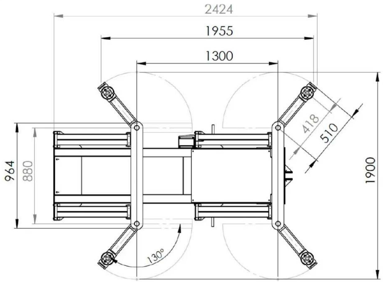
text_image
2424 1955 1300 964 880 418 510 1900 130°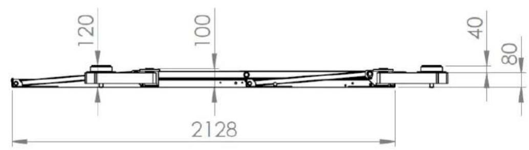
text_image
120 100 40 80 2128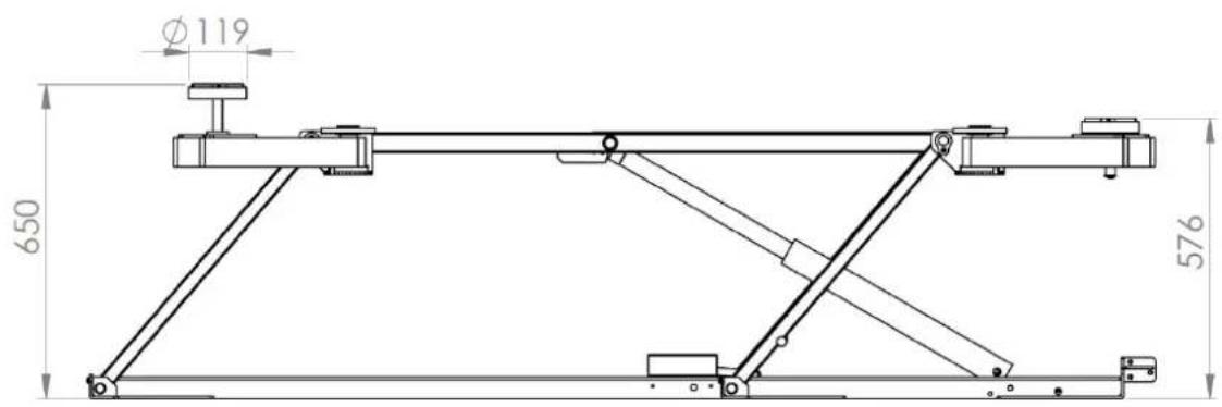
text_image
Ø119 650 576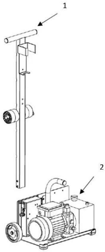
text_image
Technical diagram of a mechanical device with labeled parts 1 and 2, showing components like a vertical rod and motor assembly.
text_image
319 250 1073 389 269 545| 1 | Manoeuvring drawbar |
| 2 | Hydraulic power pack |
FEATURES
| Maximum allowed load | 2,000 kg /4400 lbs |
| Type of vehicle allowed | Tourism vehicle |
| Electrical installation | 230V AC1 ~ 50Hz |
| Power 0,75Kw | |
| Oil tank capacity | 4L |
| Noise level | <70 dB (A) |
| Rising time | Approx. 45 sec. with maximum load |
| Protection rating | IP 54 |
| Empty weight of the lift (without packaging) | 247 kg |
| Empty weight of the lift (without packaging) | 282 kg |
| Product size with packaging | L= 226cm W=108cm H=69cm |
NAMEPLATE
The technical nameplate is located on the rear of the hydraulic unit where you will find the serial number of the product, the year and month of manufacture. The tracking number can also be found in duplicate on the lift and in this manual on page 1. If one of the labels is damaged, please contact your distributor or the after-sales service department to have a new one made.

text_image
QR code image containing encoded data, no visible human-readable text-
- 0
56817.0
00001
Serial number: 20.07.056817.000001
Year of manufacture: 20 (2020)
Month of manufacture: 07 (July)
Part number: 056817
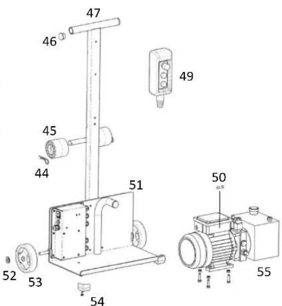
SPARE PARTS
text_image
Technical diagram of a mechanical assembly with numbered components, likely for assembly or maintenance reference.| N° | Ref. | Designation |
| 1 | 93607ST | Phosphated skate support |
| 2 | 55239 | Round rubber pad 119 x 31 |
| 3 | 93610ST | Original phosphate-plated lifting table shoe |
| 4 | 93613RI | Lift table arm Red 3020 |
| 5 | 93792ST | Phosphated lifting table arm axis |
| 6 | 43267 | Axis brake for tumbler ∅30 raw steel din 6799 |
| 7-a | 93832ST | Phosphated arm indexing plate |
| 7-b | K0139ST | Ergolift phosphated indexing notches |
| 7-c | 41266 | Schnorr safety washer type S M8x13x1.4 |
| 7-d | 43244 | Screw mx M8x16 CHC low head zn white cl 10.9 |
| 8 | 93796GF | Upper frame lifting table Grey 7021 |
| 9 | 93572GF | Lift table top frame housing Grey 7021 |
| 10 | 93562ST | Phosphated Bati Sup Axis |
| 11 | 93793ST | Pivot bielle table élévatrice phosaphaté |
| 12 | 93777GF | Front connecting rod lifting table Grey 7021 |
| 13 | 71961 | Adjustable roller lever limit switch1NO/1NC 10A 400V 0.1N |
| 14 | 93594GF | Lift table sensor housing Grey 7021 |
| 15 | 93592GF | Lift table sensor housing Grey 7021 |
| 16 | 93784GF | Connecting rod ARD lifting table Grey 7021 |
| 17 | 93782GF | Connecting rod ARG lifting table Grey 7021 |
| 18 | 93795ST | Phosphated lifting table tiller guide plate |
| 19 | 93791GF | Lower frame lifting table Grey 7021 |
| 20 | 93564ST | Baked Phosphated Cylinder Axis |
| 21 | 70888 | Single-acting cylinder left |
| 22 | 70889 | Straight single-acting cylinder |
| N° | Ref. | Designation | |
| 23 | 71 | 095-3 | BS 3/8 clip |
| 24 | 71 | 095-2 | Hollow banjo screw 3/8 gas |
| 25 | 71982+71983+ 71984 | Banjo GAS welded with tube 06-3/8 x 12L=200mm+ Nut DN 12 banjo pipe - EC 12L+ Clips DN 12 bango pipe - BA 12L/S | |
| 27 | 71 | 637 | Union Male BSP 3/8-Male BSP 3/8 |
| 28 | 71 | 402 | Union male/female 3/8 GAS L=48mm |
| 29 | 55 | 104 | compensated flow limiter 3L/min |
| 30 | 71 | 981 | Male/female elbow - CMF 12L NE |
| 31 | 71 | 980 | Union male 3/8 CYL - UMCY 12L3/8 JENE |
| 32 | 93 | 794 | Alu block solenoid valve lifting table |
| 33 | 51 | 842 | Male plug stainless steel G1/8 hexagon socket + mounting gasket NBR 90SH |
| 34 | 70 | 992 | 2-way solenoid valve 220V AC fem/Fem UNF 3/4-16 |
| 35 | 71165 | Cable Gland Black PG11 5-10mm UL without nut | |
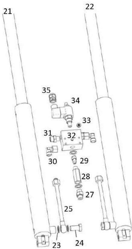
text_image
21 35 34 33 31 32 30 29 28 27 25 23 24 22| N° | Ref. | Designation |
| 36 | 55297 | Nitrile gasket 1mm thick |
| 37 | E0011C | Lift table circuit (E0011A / 65175ind1) |
| 38 | 52463 | Protective cover for Button 22 x 30 |
| 39 | 52460 | Orange illuminated switch 230V - Box 22/30 - Marking O-I |
| 40 | 51371 | Fuse T1.25A – 250 VAC – 5 x 20 |
| 42 | 92213GF | Electronic board case Grey 7021 |
| 43 | 71165 | Cable gland PG11 |
| 56 | 71161 | Cable gland PG9 |
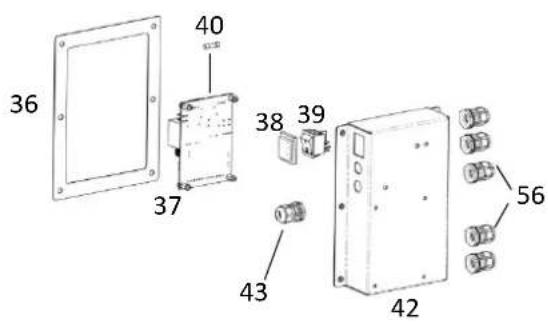
text_image
36 40 37 38 39 43 42 56| N° | Ref. | Designation | |
| 44 | 43 | 255 | Pin beta 3x56 zn white |
| 45 | 56 | 209 | Wheel D=80mm L=70mm axis 20mm |
| 46 | 43 | 101 | Closure plug Dint=28 Dext=30 Pe black |
| 47 | 96 | 167GF | Lift table drawbar Grey 7021 |
| 49 | 70 | 886 | 2-button remote control and emergency stop |
| 50 | 51 | 365 | Fuse T10A - 250 VAC – 5 x 20 |
| 51 | 92215 | Support plate for hydraulic power pack lifting table Grey 7021 | |
| 52 | 71 | 380 | Wheel fixing washer diameter=12 |
| 53 | 71 | 370 | Wheel Diameter=125mm Axis=12mm Width=35mm caps black |
| 54 | 56 | 061 | Gys 1-Angle 1-Point Shoe (40x40x30 TPE/TPR 80sh) |
| 55 | 71 | 814 | Complete hydraulic unit |
text_image
Technical diagram of a mechanical device with numbered parts and labeled parts, including a motor and electrical components.PRODUCT INFORMATION
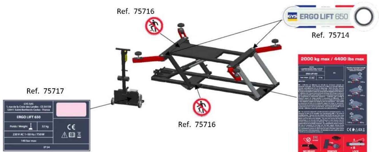
text_image
Ref. 75716 Ref. 75714 Ref. 75717 Ref. 75716 2000 kg max / 4400 lbs max GYS 545 L'au de la Crecie des Landes - CS 54139 E2941 Saint-Berthuis Cabeux - France ERGO LIFT 650 Poids / Weight 32 kg 230V AC 1-50 Hz / 750W 140 bar max IP 54 No Brake REMOVE LOCKRef. 75715
Hydraulic circuit
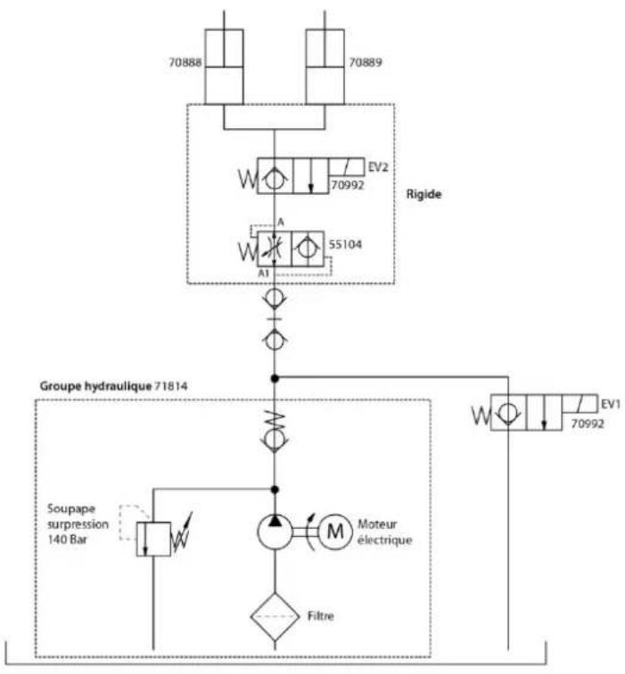
flowchart
graph TD
    A["70888"] --> B["Rigide"]
    C["70889"] --> B
    D["70992"] --> B
    E["55104"] --> B
    F["70992"] --> G["Groupe hydraulique 71814"]
    H["Soupape suppression 140 Bar"] --> I["Moteur électrique"]
    I --> J["Filtre"]
    K["EV2"] --> B
    L["A"] --> B
    M["A1"] --> B
    N["Ev1"] --> G
Electric circuit
Ref. 21459 : 3x1.5mm ^2 - H05WF / electrical outlet CE
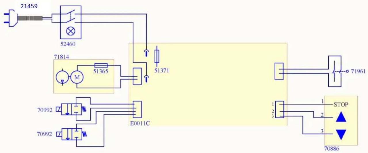
flowchart
graph TD
    A["21459"] --> B["52460"]
    B --> C["71814"]
    C --> D["M"]
    D --> E["51365"]
    E --> F["51371"]
    F --> G["E0011C"]
    H["70992"] --> I["70992"]
    J["70992"] --> K["70992"]
    L["STOP"] --> M["70886"]
    N["1"] --> O["2"]
    P["2"] --> Q["3"]
R E G U L A R S A F E T Y
| Description of the product ERGO LIFT 650 | |
| Serial number | |
| Verification phase | OK | NOT OK | Remarks |
| Presence of the technical panel on the hydraulic unit with the serial number of the lift | |||
| Presence of the maximum load of 2000kg/4400lbs on the lift with the serial number. | |||
| Up and down signalling by an arrow on the remote control | |||
| Presence of the operating instructions (original) | |||
| Tightening of nuts on all axes | |||
| Condition of hydraulic hoses and couplings | |||
| Status of the wired remote control and its power cord | |||
| The buttons on the wired remote control return to the initial position automatically and charging stops. | |||
| The emergency stop button is functional. | |||
| Condition of the load-bearing construction (mechanical structure) | |||
| Functioning of the locking notches of the 4 supporting elements and presence of the angular stops and locking of the runners in their supports. | |||
| Condition of the cylinders (leaks, rust...) | |||
| Condition of the rubber pads | |||
| Condition of the power cord of the hydraulic power pack | |||
| General condition of the hydraulic unit | |||
| Double beep when the lift reaches its maximum position. | |||
| Each time the descent button is pressed, a beep will sound for 2 seconds before the table is lowered and an audible signal will be emitted throughout the descent. | |||
| Functional test of the lifting platform with vehicle (ideally with a weight close to 2T / 4400lbs) |
| Control result | |
| Commissioning is not allowed | |
| No anomalies: commissioning granted | |
Security check carried out on: ....
Name and address of the authorised person: ....
Signature of the authorised person
M A I N T E N A N C E L O G
Purchase date: ____ started by: ____ on the ____ / ____ /20 ____
Archiving of monthly and annual checks: tick the boxes to certify periodic checks.
| Year____ | ||||||||||||
| Months | January | February | March | April | May | June | July | August | September | October | November | December |
| Controlled | ||||||||||||
| Year____ | ||||||||||||
| Months | January | February | March | April | May | June | July | August | September | October | November | December |
| Controlled | ||||||||||||
| Year____ | ||||||||||||
| Months | January | February | March | April | May | June | July | August | September | November | December | |
| Controlled | ||||||||||||
| Year____ | ||||||||||||
| Months | January | February | March | April | May | June | July | August | September | October | November | December |
| Controlled | ||||||||||||
| Year____ | ||||||||||||
| Months | January | February | March | April | May | June | July | August | September | October | November | December |
| Controlled | ||||||||||||
| Year____ | ||||||||||||
| Months | January | February | March | April | May | June | July | August | September | October | November | December |
| Controlled | May | June | July | August | September | October | November | December | ||||
| Year____ | ||||||||||||
| Months | January | February | March | April | May | June | July | August | September | October | November | December |
| Controlled | ||||||||||||
| Year____ | ||||||||||||
| Months | January | February | March | April | May | June | July | August | October | November | December | |
| Controlled | ||||||||||||
| Year____ | ||||||||||||
| Months | January | February | March | April | May | June | July | August | September | October | November | December |
| Controlled | ||||||||||||
| Year____ | ||||||||||||
| Months | January | February | March | April | May | June | July | August | September | October | November | December |
| Controlled | ||||||||||||
I C O N S
 | - Warning ! Read the instructions manual before use. |
| CE | - Machine compliant with European directives The compliance declaration is available on our website. |
| [SWWD] | - This hardware is subject to waste collection according to the European directives 2002/96/UE.Do not throw out in a domestic bin ! |
| IP 54 | Protects against the intrusion of dust and water splashes from all directions. |
| CMU 2000Kg | -The maximum working load (MWL) is 2000kg / 4400lbs |
 | -Do not mount on this element. |
 | Equipment in compliance with British requirements. The British Declaration of Conformity is available on our website (see home page). |
