Trolley IW1 - Industrial rolling cart GYS - Free user manual and instructions
Find the device manual for free Trolley IW1 GYS in PDF.
| Product type | Mobile impact wrench holder (industrial rolling cart) |
| Brand | GYS |
| Model | Trolley IW1 |
| Empty weight | 70 kg |
| Balancing capacity | 1 to 20 kg (wrench + accessories) |
| Height | 95 cm |
| Width | 85 cm |
| Depth | 86 cm |
| Pneumatic supply | 1/2\" male connector, max pressure 10 bar, recommended pressure 6 to 6.5 bar |
| Minimum air flow | Depends on the impact wrench used |
| Lubrication | ISO 22 oil (ISO 32 possible), adjustment per wrench manufacturer |
| Balancing adjustment | Screw under the seat, ratchet wrench with 21 mm spark plug socket (not included) |
| Parking brake | Hand brake synchronized on both rear wheels |
| Arm locking | Safety pins for transport and storage |
| Filter, regulator, lubricator (FRL) | Integrated, with dry output for inflation |
| Wrench mounting interface | 36 mm to 44 mm square drive |
| Operating temperature | 5 °C to 50 °C |
| Storage temperature | 0 °C to 60 °C |
| Warranty | 2 years |
| Regular maintenance | Lubrication of joints, check cable and fasteners, drain filter |
| Cleaning | Soft cloth, suitable product for painted steel; avoid high-pressure jet |
| Spare parts | Available via manufacturer (references listed in manual) |
| Repairability | Designed for professional maintenance; disassembly possible by following reverse steps |
| Standards | Machinery Directive 2006/42/EC, EN ISO 12100:2010 |
Frequently Asked Questions - Trolley IW1 GYS
User questions about Trolley IW1 GYS
0 question about this device. Answer the ones you know or ask your own.
Ask a new question about this device
Download the instructions for your Industrial rolling cart in PDF format for free! Find your manual Trolley IW1 - GYS and take your electronic device back in hand. On this page are published all the documents necessary for the use of your device. Trolley IW1 by GYS.
USER MANUAL Trolley IW1 GYS
natural_image
Technical line drawing of a mechanical device with wheels and a handle (no text or symbols)Video
FR 01 / 15
TROLLEY IW1
EN 16 / 32
CONSIGNE GÉNÉRALE

natural_image
Isometric line drawing of a 3D rectangular prism with dashed internal lines and corner markers (no text or symbols)natural_image
Isometric line drawing of a rectangular box with labeled corners (no text or symbols on the object itself)natural_image
Technical line drawing of a mechanical assembly with mounting bracket and rail (no text or symbols)natural_image
Pure mechanical diagram showing a pulley, gear, and hexagonal nut with no text or symbolsnatural_image
Pure mechanical diagram with no text, numbers, or symbolsnatural_image
Technical line drawing of a mechanical assembly with no visible text or symbolsFREIN
DÉCLARATION DE CONFORMITÉ
This user's manual includes operating instructions for your device and safety warnings for your protection. Please read it carefully before first use and keep it for future reference.
Do not use this machine if any parts are missing or damaged.
This product must not be modified in any way.
Fasteners that are over- or under-torqued and susceptible to breakage, loosening or separation can lead to serious accidents. Unsecured components can become projectiles. Assemblies that require a specific torque should be checked with a dynamometer.
If the markings indicating the rated load, working pressure or warning signs are illegible or missing, they must be replaced.
Operators and maintenance personnel must be physically capable of supporting the load, weight and power of the connected equipment and must be able to perform the work.
This equipment is intended for professional use only.
PERSONAL SAFETY

Wear safety shoes to avoid an accident in the event of falling parts or during the machine's assembly.

Wear protective gloves to limit the risks associated with vibration exposure.
Repeated movement and exposure to vibrations can be harmful to both the hands and arms. In the event of numbness, itching, pain or discolouration of the skin, stop using the device and consult a doctor.

Wear ear protection. Prolonged exposure to the operating noise of an air tool can result in permanent hearing loss.
WORKING ENVIRONMENT
Slips, trips or falls are a major cause of serious injury or death. Look out for loose cables on the floor. Always use the tool at a safe distance from people and objects in or around the work area.
The impact-wrench support is intended for indoor use, in a well-lit environment on a flat floor.
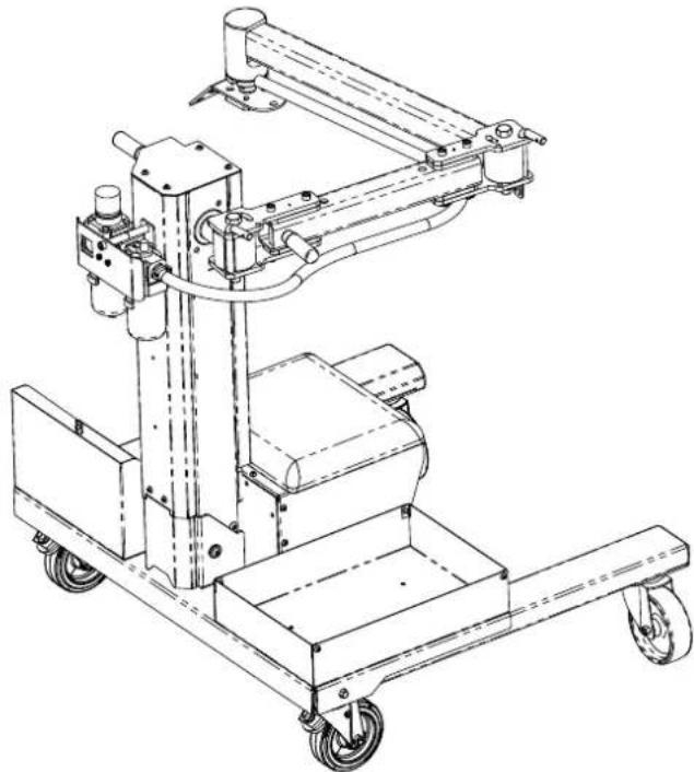
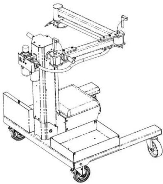
DESCRIPTION OF THE IMPACT-WRENCH SUPPORT
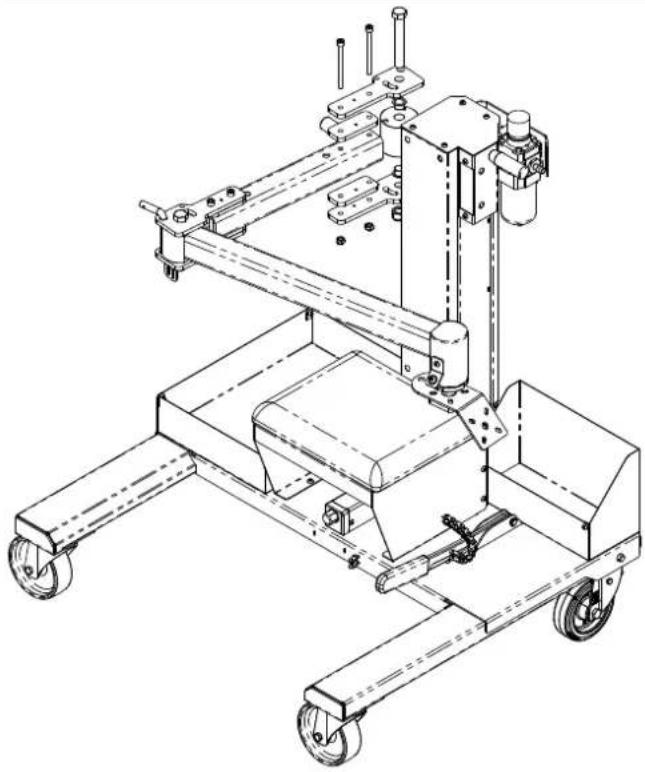
The impact-wrench support is a user-friendly tool that makes it easier to use impact wrenches for heavy good vehicles. It allows an operator to support the impact wrench's weight and torque as well as some of the vibrations when the device is used on a heavy goods vehicle. It enables the user to move around the vehicle easily and to hold the equipment firmly in its working position thanks to its brake. It balances a wide range of weights and can be fitted with an inflation device and a silencer. It is ideal for working on all types of HGV tyres and also offers better access to the underbody.
COMPONENT PARTS
The impact-wrench support consists of numerous parts. The positioning of these component parts is shown on the following pages. Contact the manufacturer, GYS, for more information about the part numbers.
ASSEMBLY
NUTS AND SCREWS
| Ref. Désignation Quantity Image | ||
| 41017 Screw (M8x16) 16 |  | |
| 41288 Torx oval-head screw (M6x10) 29 |  | |
| 41283 Torx oval-head screw (M5x9) with captive washer 8 |  | |
| 42171 Hexagonal head screw (M8x95) 5 | ||
| 41028 Torx oval-head screw (M6x30) 8 | ||
| 41150 Lock nut M8 6 | ||
| 42090 Flat-head screw (M5x12) 4 | ||
| 71353 Hexagonal socket screw plug (G1/4) with seal 1 | ||
| 43122 Hexagonal M/F spacing sleeve (M5x8x12) 4 | ||
| 42151 M5 lock nut 4 | ||
| 43286 Lock nut (M16) 2 | ||
| 43288 Hexagonal-head screw (M16x110x38) 2 | ||
| 43300 Crosshead countersunk-head wood screw (M3x10) 4 | ||
| 41155 Standard nut (M5) 2 | ||
| 41180 Lock nut (M6) 4 |
TOOLS
| Product Name | Size | Quantity | Image |
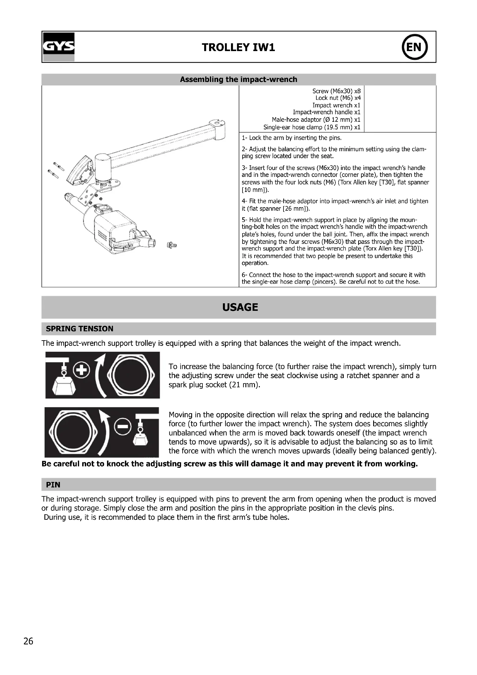
| Torx Allen key | T25 | 1 | |
| T30 | 1 | ||
| Allen key | H6 | 1 | 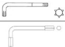 |
| Flat spanner | 8 | 1 | |
| 10 | 1 | ||
| 13 | 1 | ||
| 22 | 1 |  | |
| 24 | 2 | ||
| 26 | 1 | ||
| Sleeve | 13 | 1 | |
| 19 | 1 |  | |
| 24 | 2 | ||
| 26 | 1 | ||
| Crosshead screwdriver | PZ1 | 1 |  |
| Slotted screwdriver | SL7 | 1 |  |
| Pincers | - | 1 | 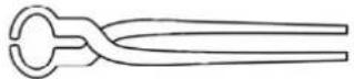 |
| Combination pliers | - | 1 | 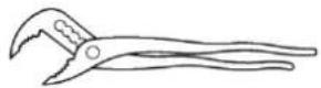 |
| Mallet | - | 1 | 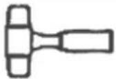 |
PARTS
| Ref. Product Name Quantity Image | |||
| 71367 Castor wheel (D125 mm H155 mm) 2 | 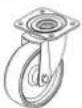 | ||
| 71209 | Cable ties made from black polypropylene (PP) (4.8 mm x 295 mm) | 2 | |
| 94526 Hose (L1760 mm D12x19 mm) 1 |  | ||
| 51832 L-shaped rod (L101 mm x D55 mm) 2 |  | ||
| 42173 Single-ear hose clamp (19.5 mm) 3 |  | ||
| 55291 Filter, regulator and lubricator (FRL) 1 | 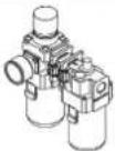 | ||
| 71891 | Castor wheels with central brake (D125 mm) | 2 | 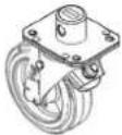 |
| 93437 Clevis joint and inter-arm support 2 | 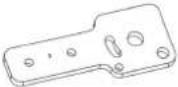 | ||
| 93438 Clevis with stop arm No. 1 2 | 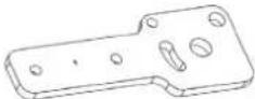 | ||
| 93439 Fixing plate No. 1 2 |  | ||
| 93440 Fixing plate No. 2 2 |  | ||
| 93451 Impact-wrench cord attachment 1 |  | ||
| 93474 Front casing | 1 |  | |
| 93871 Bolt-storage unit | 1 |  | |
| 93872 Seat | 1 | 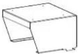 | |
| 93874 Tapped plate for stop screws | 1 | 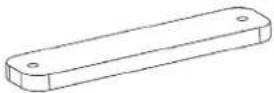 | |
| 93909 Column top 1 | 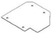 | ||
| 93908 Seat base 1 | 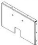 | ||
| 93887 Spacer between column and seat 2 | 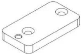 | ||
| 93877 First arm 1 | 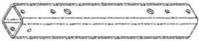 | ||
| 93480 Second welding arm & Locking pin (Ø8 mm x 32 mm) | 1 + 2 | 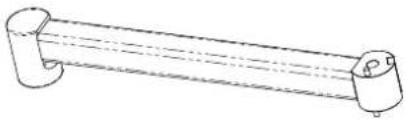 | |
| 93998 FRL casing 1 |  | ||
| 93476 Tongued washer 1 | 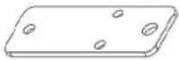 | ||
| 42106 Stainless steel cable (L200 mm) with two rings (D24 mm) | 2 | 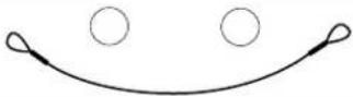 | |
| 93870 Lower-rear casing 1 |  | ||
| 93893 Sleeve box 1 | 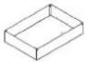 | ||
| 51204 Impact-wrench support pad | 1 | 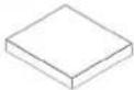 | |
| 43281 Spacing sleeve (D8.2x12 mm L40 mm) | 2 |  | |
| 72070 Straightening bar handle (M8x10 H81) | 2 |  | |
| 43234 Flanged bearing (D18 mm Ø 16 mm) | 4 |  | |
| 42223 Male-hose adaptor (Ø 12 mm) | 3 |  | |
ASSEMBLY PROCEDURE
Fitting the rear wheels
| Screw (M8 x 16) x8 Castor wheels with central brake (D125) x2 | Torx Allen key (T30) Allen key (H6) Mallet |
| 1- Apply the brakes using the pedal. 2- Loosen the screw between the connecting rod and the hexagonal bar to be able to slide the bar to one side without taking it out completely (Torx Allen key [T30]). 3- Insert the castor wheel into the plate, then pass the bar through the wheel cavity until it protrudes through. 4- Position the four wheel screws without tightening them (screws [M8x16], Allen key [H6]). 5- Insert the other wheel in the opposite plate then replace the hexagonal bar and tighten the screw between the connecting rod and the bar (tapped hole, Torx Allen key [T30] and a mallet if necessary). 6- Insert the four M8x16 wheel screws and tighten them all (Allen key [H6]). |
Fitting the front wheels
| Screw (M8x16) x8 Castor wheel (D125 H155) x2 | Allen key (H6) |
| 1- Place the wheels on the two front plates. 2- Position the eight wheel screws and tighten them (screws [M8x 6], Allen key [H6]). | |
Mounting the column
| Lock nut (M8) x2 | Spanner or 13 mm socket spanner |
| 1- Apply the brakes and position the column (the brake will remain applied for the product's entire assembly procedure). 2- Insert the two lock nuts (M8) and tighten them to prevent the column from closing and to keep it straight (spanner or 13 mm socket spanner). | |
Assembling the lower-rear casing
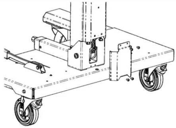 | Screw (M6x10) x4Lower-rear casing x1 | Torx Allen key (T30) |
| 1- Position the lower-rear casing so that the top part of it is behind the upper-rear housing, lining up the screw holes (see pictures).2- Position and tighten the four screws (M6x10) (Torx Allen key [T30]). | ||
Assembling the column
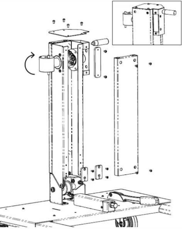 | Torx oval-head screw (M5x9) with captive washer x4Screw (M6x10) x6Flat-head screws (M5x12) x4Straightening bar handle (M8x10 H81) x1Column top x1 Front casing x1Spacer between column and seat x2Tapped plate for stop screws x1 | Torx Allen key (T25 and T30) |
| 1- Holding the column's shaft in place, rotate the mechanism clockwise to wind the chain onto the pulley, then position the tapped plate for stop screws inside the casing unit attached to the right-hand side of the column (see pictures).2- Hold it in place with two screws (M6x10) (Torx Allen key [T30]).3- Position the four Torx oval-head screws (M5x9) with captive washer on the column, then insert the front casing by passing the screw heads through the small holes.4- Place the casing against the column and slide it down. When it is fully down, tighten the four screws (M5x9) with captive washers (Torx Allen key [T25]).5- Place the spacers between the column and the seat with the spacers' tapped holes facing downwards. Tighten the flat-head screws (M5x12) to hold the spacers in place (Torx Allen key [T25]).6- Position the column top and hold it in place with the four screws (M6x10) (Torx Allen key [T30]).7- Screw the handle into the casing on the right-hand side of the column. | ||
Assembling the seat
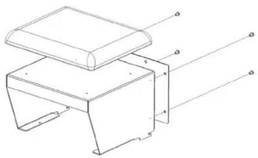 | Torx oval-head screw (M6x10) x8Crosshead countersunk-head wood screw (M3x10) x4 | Torx Allen key (T30) |
| 1- Place the pad on a clean, flat surface with the bottom facing up.2- Turn the seat upside down as well and attach it to the cushion, making sure that it is properly aligned with the cushion (sides and front aligned with the seat's metal base).3- Insert the seat bottom into the seat and secure it with the 4 M6 x 10 screws. (Torx key T30) | ||
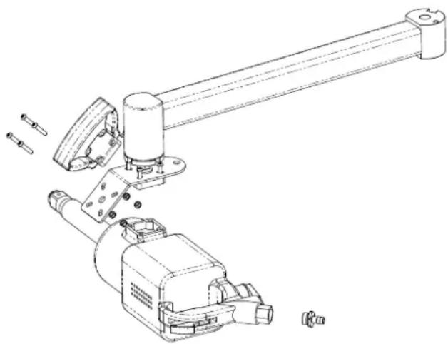
Front-arm assembly
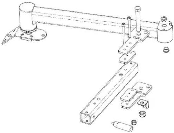 | Nut (M12x1) x1Hexagonal lock nut (M14x1.5) x1Axial rod x1Ball-joint bellows x1Tongued washer x1Second welding arm x1 Impact-wrench plate x1Impact-wrench connector x1 | Flat spanner (22 mm)Sleeve (19 mm)Flat screwdriver (SL7)Mallet |
| 1- Insert the axial rod's small pin into the impact-wrench connector and then into the impact-wrench plate. Firmly tighten the nut (M12x1) (Sleeve [19 mm] and clamping the ball joint if necessary). Pay attention to the alignment of the impact-wrench's screw holes.2- Slide the ball-joint bellows onto the axial rod's large pin until it reaches the smooth part.3- Position the hexagonal lock nut (M14x1.5) onto the rod.4- Put the tongued washer on tot axial rod with the fold going up in the opposite direction to the nut (see pictures). Then, screw the axial rod into the second welding arm by positioning the tongued washer's fold into the arm's slot.5- Firmly tighten the nut (M14x1.5) onto the tongued washer (22 mm spanner).6- Fold the tongued washer as shown in the picture using a mallet and a flat screwdriver. | ||
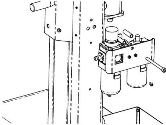
FRL (filter, regulator and lubricator) assembly
 | Screw (M8x95) x1Nut (M5) x2Lock nut (M5) x4Hexagonal M/F spacer (M5x8x12) x4Hexagonal socket plug with seal (G1/4) x1Male-hose adaptor (∅ 12 mm) x2Hexagonal M/F spacing sleeve(M5x8x12) x2Filter, regulator and lubricator (FRL) x1FRL plate x1FRL casing x1 | Flat spanner (8 mm)Flat spanner (26 mm)Allen key (H6) |
| 1- Replace the two hollow hexagonal nuts on the front of the FRL with standard nuts (M5)(max. tightening cut [4 N.m], Allen key [H5], flat spanner [8 mm]).2- Place the four hexagonal M/F spacers (M5x8x12) over the standard nuts (front and rear) and tighten them to the same torque (4 N.m),(flat spanner [8 mm]).3- Position the FRL casing onto the hexagonal M/F spacers (M5x8x12) at the front and then hold it with two lock nuts (flat spanner [8 mm]).4- Insert the screw (M8x95) into the FRL casing, the hexagonal M/F spacers (D8.2x12, L40) and the FRL plate. Then, fix the FRL plate onto the hexagonal M/F spacers (M5x8x12) with two lock nuts (M5), (flat spanner [8 mm]).5- Insert the hexagonal socket plug with seal (G1/4) into the outlet under the FRL (Allen key [H6]). It is possible to replace the plug with a specific fitting that allows the outlet to be used for inflation or other purposes.6- Fit the two hexagonal M/F spacing sleeves (M5x8x12) to the FRL unit (inlet and outlet) (flat spanner [26 mm]). | ||
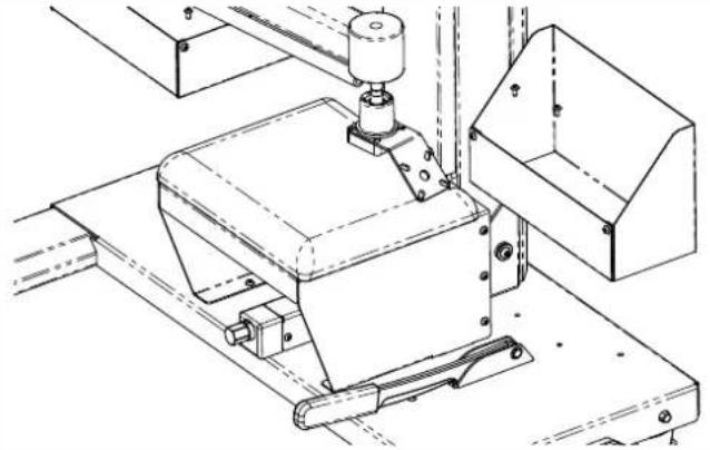
Assembling the bolt-storage unit
 | Screw (M6x10) x2 Bolt-storage unit x1 | Torx Allen key (T30) |
| 1- Secure the box using the two screws (M6x10) (Torx Allen key [T30]). | ||
Assembling the sleeve-box unit
 | Screw (M6x10) x4 Sleeve box x1 | Torx Allen key (T30) |
| 1- Secure the box using the four screws (M6x10) screws (Torx Allen key [T30]). | ||
Seat assembly
 | Screw (M6x10) x4Assembled seat x1 | Torx Allen key (T30) |
| 1- Place the seat's hooks into the notches on the tray, then push the seat towards the column.2- Attach the seat to the column by tightening the two screws (M6x10) which go through the bottom of the seat and screw into the spacers between the column and the seat.3- Position the two remaining screws for attaching the seat into the folds inside the seat (on the tray). | ||
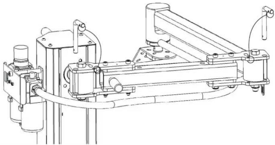
Arm assembly
 | Hexagonal-head screw (M16x110x38) x1Socket-head screw (M8x95) x2Lock nut (M16) x1Lock nut (M8) x2Clevis joint and inter-arm support (engraved 1) x2Fixing plate No. 1 (engraved 1) x2Assembled arm x1 | Allen key (H6)Socket spanner (13 mm) x1Socket spanner(24 mm) x1 |
| 1- Insert the flanged bearings into the holes on the shaft close to where it meets the column, then grease the inside of the bearings, the plastic and metal faces as well as the shaft's connecting pins at the top of the column with neutral grease.2- Grease and insert the hexagonal-head screws (M16x110x38) into the clevis joint (1), through the bearings on the shaft at the top of the column and the other clevis joint (1) in this order (see pictures). Then, position the lock nut (M16) without tightening it. (by hand). Pay attention to the direction of the clevis joints ensuring the holes are all aligned. The shaft's pins at the top of the column must be in the clevis joint's bean-shaped holes.3- Insert the screws (M8x95) into the upper clevis joint (1), the plate (1), then the arm, the other plate (1) and the lower clevis joint (1).4- Firmly tighten the lock nuts (M8) onto the screws (M8x95) (socket spanner [13 mm] and Allen key [H6]). Firmly tighten the nut (M16) onto the screw (M16), then loosen the nut with a 1/8 turn (socket spanner [24 mm]). | ||
FRL assembly
 | Screws (M6x10) x1Assembled FRL unit x1 | Torx Allen key (T30)Allen key (H6) |
| 1- Fix the screw (M8x95) into the corresponding hole on the product's upper-rear casing (low torque [4 N.m], Allen key [H6]).2- Fix the bottom of the FRL plate to the upper-rear casing using the screw (M6x10) (low torque [4 N.m], Torx Allen key [T30]). | ||
Assembling the bolt-storage unit
 | Screws (M5x9) with washer x2Assembled bolt-storage unit x1 | Torx Allen key (T25) |
| 1- Affix the bolt-storage unit using the two screws (M5x9) with washers (Torx Allen key [T25]). | ||
Assembling the socket box
 | Screws (M5x9) with washer x2Assembled socket box x1 | Torx Allen key (T25) |
| 1- Affix the socket box with the two screws (M5x9) with washers (Torx Allen key [T25]). | ||
Assembling the hoses
 | Pipe (D12x19 L1760) x1Cable ties made from black polypropylene (PP) (4.8 mm x 295 mm) x2Single-ear hose clamp (19.5 mm) x1 | Pincers |
| 1- Thread the hose from the FRL outlet, then push the hose into the fsingle-ear hose clamp (19.5 mm) fitting (pincers). Be careful not to cut the hose.2- Attach the hose to the arm and/or the impact-wrench cord attachment using the cable ties made from black polypropylene. | ||
Assembling the pins
 | Stainless steel cable (L200 mm) with two rings (D24 mm) x2L-shaped rod (L101 mm x D55 mm) x2 | Torx Allen key (T30)Flat spanner (10 mm)x1Flat spanner (26 mm)x1Pincers |
| 1- Mount the cables on clevises with pins and then position them in place. | ||
Assembling the impact-wrench
 | Screw (M6x30) x8Lock nut (M6) x4Impact wrench x1Impact-wrench handle x1Male-hose adaptor (∅ 12 mm) x1Single-ear hose clamp (19.5 mm) x1 | |
| 1- Lock the arm by inserting the pins.2- Adjust the balancing effort to the minimum setting using the clamping screw located under the seat.3- Insert four of the screws (M6x30) into the impact wrench's handle and in the impact-wrench connector (corner plate), then tighten the screws with the four lock nuts (M6) (Torx Allen key [T30], flat spanner [10 mm]).4- Fit the male-hose adaptor into impact-wrench's air inlet and tighten it (flat spanner [26 mm]).5- Hold the impact-wrench support in place by aligning the mounting-bolt holes on the impact wrench's handle with the impact-wrench plate's holes, found under the ball joint. Then, affix the impact wrench by tightening the four screws (M6x30) that pass through the impact-wrench support and the impact-wrench plate (Torx Allen key [T30]). It is recommended that two people be present to undertake this operation.6- Connect the hose to the impact-wrench support and secure it with the single-ear hose clamp (pincers). Be careful not to cut the hose. | ||
USAGE
SPRING TENSION
The impact-wrench support trolley is equipped with a spring that balances the weight of the impact wrench.

natural_image
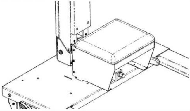
Pure mechanical diagram showing a pulley, gear, and hexagonal nut with no text or symbolsTo increase the balancing force (to further raise the impact wrench), simply turn the adjusting screw under the seat clockwise using a ratchet spanner and a spark plug socket (21 mm).

natural_image
Pure mechanical diagram showing a hex nut, curved arrow, and lever (no text or symbols)Moving in the opposite direction will relax the spring and reduce the balancing force (to further lower the impact wrench). The system does become slightly unbalanced when the arm is moved back towards oneself (the impact wrench tends to move upwards), so it is advisable to adjust the balancing so as to limit the force with which the wrench moves upwards (ideally being balanced gently).
Be careful not to knock the adjusting screw as this will damage it and may prevent it from working.
PIN
The impact-wrench support trolley is equipped with pins to prevent the arm from opening when the product is moved or during storage. Simply close the arm and position the pins in the appropriate position in the clevis pins. During use, it is recommended to place them in the first arm's tube holes.
natural_image
Technical line drawing of a mechanical assembly with no visible text or symbolsBRAKE
The impact-wrench support trolley is equipped with a synchronised hand brake that acts on each of the two rear wheels. It is operated by pulling up the handle on the left when sitting on the seat. It is deactivated by lowering this handle.
AIR TREATMENT
The impact-wrench support trolley comes with a filter, regulator and lubricator unit (FRL).
It is recommended to connect it to a specific air network with half-inch (1.27 cm) connections enabling an increased air flow.

The recommended operating air pressure is 6 to 6.5 bar (0.6 to 0.65 MPa). The maximum pressure is 10 bars.
It is possible to add a quarter-inch (6 mm) quick connector between the filter regulator and the lubricator to connect a pump or any other pneumatic accessory.
A silencer and/or coalescing filter can be fitted to the machine to separate any oil from the impact wench's returning airflow; this recycles the used oil and avoids oil mist in the return airflow or the impact wrench's air outlet.
SAFETY DURING USE AND TRAVEL

Be aware the risk of electric shocks when bringing the impact wrench back towards yourself. Set a balancing force that is just sufficient.
Always lock the arm in place with the pins when moving the device. Do not sit on the impact-wrench support trolley to avoid opening the arm and increasing the risk of electric shocks.
Take particular care when passing through doorways, over electrical wires or other objects on the ground.
Handles must be gripped in a way that prevents you from hitting your hands on objects protruding from the wall, shelves or other objects.
INSERTING AND CHANGING THE IMPACT-WRENCH SUPPORT

The user is responsible for the correct installation or replacement of the impact-wrench support. As described in the section 'Assembling the impact-wrench'.
Always use a chock behind the rear wheels when installing/changing the impact-wrench support.
Always secure the arm with locking pins when fitting/changing the impact-wrench support.
Always set the balancing force to the minimum when fitting/changing the impact-wrench support.
The impact-wrench support must always be securely fastened to the impact-wrench plate to prevent the impact wrench from falling.
It is recommended that two people carry out this operation.
The impact-wrench support's maximum load must not exceed 20 kg.
MAINTENANCE
In order for the impact-wrench support trolley to work at its best, it is important to carry out regular maintenance following the instructions below. The maintenance interval is defined according to normal use with a daily use of eight hours. For more intensive use, the maintenance should be carried out more frequently.
- Check parts for cracks or points of wear and tear.
- Check the tightness of bolts and screws. See section 'ASSEMBLY PROCEDURE' for instructions on how to tighten torques.
- Check the condition of the arm's articulated parts. Add a suitable grease (neutral grease) to moving parts (arm joints).
- Check that the castor wheels are working properly. Grease the bearings. Check that the rubber surfaces are in good condition.
- Check the condition of the filter (remove dust if necessary). Bleed the filter.
- Check that the air regulator is working properly.
- Check the oil level in the lubricator.
After assembly/disassembly, the impact-wrench attachments fitted to the plate must be checked, as well as the tapped plate attachments for the stop screws. Available in the sections entitled 'Assembling the impact-wrench' and 'Assembling the column'.
MAINTENANCE
Dusting can be done with an compressed-air blower before cleaning.
Wash the impact-wrench support trolley with a product suitable for painted steel surfaces. Follow the product's cleaning instructions. Dry the wrench-holder support with a cloth after cleaning. Never use a high-pressure sprayer as this can damage the paintwork.
TROUBLESHOOTING
The impact-wrench support trolley is designed for effective and safe use provided that the maintenance instructions have been followed. However, if you do encounter any operating problems, here is some advice. If problems persist, contact the repairer or the manufacturer.
If the arm doesn't move or has difficulty moving:
- Check that all parts of the arm are present, check the 'ASSEMBLY PROCEDURE' section.
- Check that the fixing screws are tightened to the correct torque and that the moving parts (arm joints) are properly lubricated, see section entitled 'MAINTENANCE'.
If the impact-wrench support trolley makes a strange noise: - Check that the impact-wrench support trolley's component parts are correctly mounted, see 'ASSEMBLY PROCEDURE' section.
- See section entitled 'MAINTENANCE'.
TECHNICAL SPECIFICATIONS
| Balancing capacity (impact wrench attachments) 70 Kg | |
| Product's height From 1 to 20 kg | |
| Product's width 95 cm | |
| Product's depth 85 cm | |
| Connection to the air network 86 cm | |
| Minimum airflow rate | 12'' (1.27 cm) 10 bar max. (built-in regulator)Recommended pressure, 6 to 6.5 barCan be connected in 14'' (6 mm) 10 bar max.(will lower the impact wrench's performance) |
| Débit d'air minimum Depending on the impact wrench | |
| Lubrication | Recommended oil: ISO 22 (ISO 32 will work)Adjust according to the manufacturer's recommendations |
| Impact-wrench holding connector and handle Berne key (from 36 mm to 44 mm) | |
| Adjusting the balance | Ratchet spanner with spark plug socket (21 mm)(not supplied) |
| Storage temperature 0°C à 60°C | |
| Operating temperature | 5°C à 50°C |
WARRANTY
The impact-wrench support is covered by warranty for two years starting from the date of shipment. The warranty covers defects in the hardware and/or manufacturing. This warranty is only valid if the maintenance has been carried out according to the instructions in this user manual. The warranty does not cover periodic maintenance, calibration or regular adjustments.
Labor costs related to such actions are not covered. Incidents considered to be misuse or abuse may void the warranty.
DISASSEMBLY AND RECYCLING
To disassemble the impact-wrench support, refer to the section entitled ASSEMBLY PROCEDURE and reverse the order of the instructions.
The impact-wrench support must be disposed of in accordance with the current environmental and disposal guidelines of the country in which it is located.
DECLARATION OF CONFORMITY
GYS certifies that the new product, TROLLEY IW1 (063136), has been made conforming to Directive 2006/42/CE, Machine, of 2006.05.17 and, consequently, complies with following standard:
- EN ISO 12100 : 2010
The CE marking was approved in 2019 The full declaration of conformity is available on our website.
ICÔNES
 | - Appareil conforme aux directives européennes. La déclaration de conformité est disponible sur notre site internet. – The device complies with European Directive. The certificate of compliance is available on our website. - Gerät entspricht europäischen Richtlinien. Die Konformitätserklärung finden Sie auf unsere Webseite. - El aparato está conforme a las normas europeas. La declaración de conformidad está disponible en nuestra página Web. - Устройство соответствует европейским нормам. Декларация соответствия есть на нашем сайте. - Het toestel is in overeenstemming met de Europese richtlijnen. De conformiteitsverklaring is te vinden op onze internetsite. - O aparelho está em conformidade com as directivas europeias. A declaração de conformidade está disponível no nosso website. - Dispositivo in conformità con le norme europee. La dichiarazione di conformità è disponibile sul nostro sito internet. |
 | - Matériel conforme aux exigences britanniques. La déclaration de conformité britannique est disponible sur notre site (voir à la page de couverture).- Equipment in compliance with British requirements. The British Declaration of Conformity is available on our website (see home page).- Das Gerät entspricht den britischen Richtlinien und Normen. Die Konformitätserklärung für Grossbritannien ist auf unserer Internetseite verfügbar (siehe Titelseite).- Equipo conforme a los requisitos británicos. La Declaración de Conformidad Británica está disponible en nuestra página web (véase la portada).- Материал соответствует требованиям Великобритании. Заявление о соответствии для Великобритании доступно на нашем веб-сайте (см. главную страницу).- Materiaal conform aan de Britse eisen. De Britse verklaring van overeenkomt is beschikbaar op onze website (zie omslagpagina).- Materiale conforme alla esigenze britanniche. La dichiarazione di conformità britannica è disponibile sul nostro sito (vedere pagina di copertina). |
 | Produit recyclable qui relève d'une consigne de tri. / Recyclable product that falls within waste sorting recommendations / Recyclebares Gerät, das spezifisch entsorgt werden muss (nach dem Dekret N°2014-1577) / Producto reciclable que requiere una separación determinada según el decreto n° 2014-1577 / Rekupereerbaar product dat onderworpen is aan een sorteerinstructie / Prodotto riciclabile che è soggetto ad un'istruzione di smistamento. |