C610C - Garage door opener CHAMBERLAIN - Free user manual and instructions
Find the device manual for free C610C CHAMBERLAIN in PDF.

User questions about C610C CHAMBERLAIN
0 question about this device. Answer the ones you know or ask your own.
Ask a new question about this device
Download the instructions for your Garage door opener in PDF format for free! Find your manual C610C - CHAMBERLAIN and take your electronic device back in hand. On this page are published all the documents necessary for the use of your device. C610C by CHAMBERLAIN.
USER MANUAL C610C CHAMBERLAIN
- Please read this manual and the enclosed safety materials carefully!
- Fasten the manual near the garage door after installation.
- The door WILL NOT CLOSE unless the Protector System 'is connected and properly aligned.
Periodic checks of the garage door opener are required to ensure safe operation.

- The model number label is located on the front panel of your garage door opener.
This garage door opener is compatible with MyQ® and Security+2.0® accessories. - DO NOT install on a one-piece door if using devices or features providing unattended close. Unattended devices and features are to be used ONLY with sectional doors.
Owner's Manual
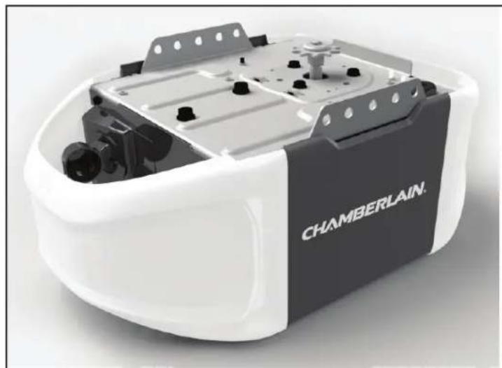
C610C
Chain Drive
Garage Door Opener
TO WATCH VIDEOS GO TO:
tinyurl.com/lgh5x3h
Contents
Preparation. 2-5
Assembly. 6-10
Installation 11-28
Install the Door Control 21-22
Install the Protector System* ....23-26
Connect Power 27
Adjustments. 29-31
Operation. 32-36
Features 31
Using your Garage Door Opener....34
Motion Detecting Control Panel.....34
Remote Control and
Keyless Entry 35
Homelink* 30
To Erase the Memory 36
To Open the Door Manually 37
Maintenance 38
Troubleshooting 39-40
Accessories. 41
Warranty. 42
Repair Parts 43-44
www.chamberlain.com
www.mychamberlain.com
Preparation
Safety Symbol and Signal Word Review
This garage door opener has been designed and tested to offer safe service pro
WARNING
Mechanical
WARNING
Electrical
CAUTION
WARNING: This product can expose you to chemicals including lead, which State of California to cause cancer or birth defects or other reproductive information go to www.P65Warnings.ca.gov
Unattended Operation
The Timer-to-Close (TTC) feature, ⑧ Sema#one Control app.and ⑧ Mage Door and Gate Monitor are examples of unattended close and are to be used ONLY w device or feature that allows the door to close withoutbeing in the line of s unattended close.The Timer-to-Close (TTC) feature, ⑧ SthartpMye Control, and anyother MyQ ③ devicesare to be used ONLY with sectional doors.
Check the Door
vided - it - isinstalled.
hs contained in
WARNING
Signaeventpossible SERIOUS INJURY or DEATH:
art . yALWY S call a trained door systems technician if garage door binds, sticks, or is out of balance. If you App unbalanced garage door may NOT reverse when required.
- NEVER tryto loosen, move or adjust garage door,door springs, cables, pulleys, bing their hardware, ALL of which are under EXTREME tension.
- Disable ALL locks and remove ALL ropes connected to garage door BEFORE installing garage door opener to avoid entanglement.
DO NOT install on a one-piece door if using devices or features providing unattended close.
pillingattended devices and features are to be used ONLY with sectional doors.
f damage
CAUTION
To prevent damage to garage door and opener:
are known to the ALWAYS disable locksBEFORE installing and operating the opener.
mth . ONLY operate garage door opener at 120V,60 Hz to avoid malfunction and
Before you begin:
- Disable locks and remove any ropes connected to the garage door.
- Lift the door halfway up. Release the door. If balanced, it should stay in place, supported entirely by its springs.
3sectional doors lowry the door to check for binding or sticking. If your door extends, doors, consider out of balance, call a trained door technician.
- Check the seal on the bottom ofthe door Anygap between and the bottom ofthe door must not exceed 1/4 inch (6) Otherwise, the safetyreversal system may network properly.
- The opener should be installed above the center of the door. If there is a torsion spring or center bearing plate in the way off the header bracket, it may be installed within 4 feet (1.2 m) to the left or right of the door center. See page 12.
Preparation
Additional Items You May Need:
Surveyour garag e a to see if you will need any of the following items:
(2) 2X4 PIECES OF WOOD
Maybe used to fasten the header bracket to the structural supports. Also garage door opener during installation and for testing the safetyreversing
- SUPPORTBRACKET AND FASTENING HARDWARE
Must be used if you have a finished ceiling in your garage.
EXTENSION BRACKETS (MODEL 041A5281-1) OR WOOD BLOCKS
Depending upon garage construction, extension brackets or wood blocks install the safetyreversing sensor.
FASTENING HARDWARE
Alternate floor mounting of the safetyreversing sensor will require hardware
DOOR REINFORCEMENT
Required if you have a lightweight steel, aluminum,fiberglass glasspanel
RAIL EXTENSION KIT
Required if your garage door is more than 7 feet (2.13 m) high.
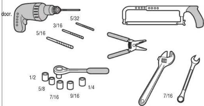
Tools Needed
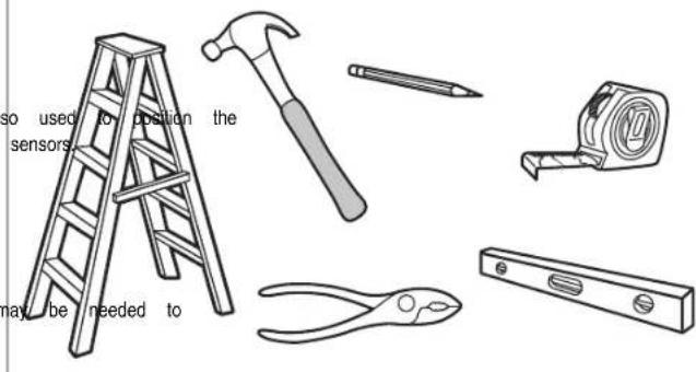
not provided.
Preparation
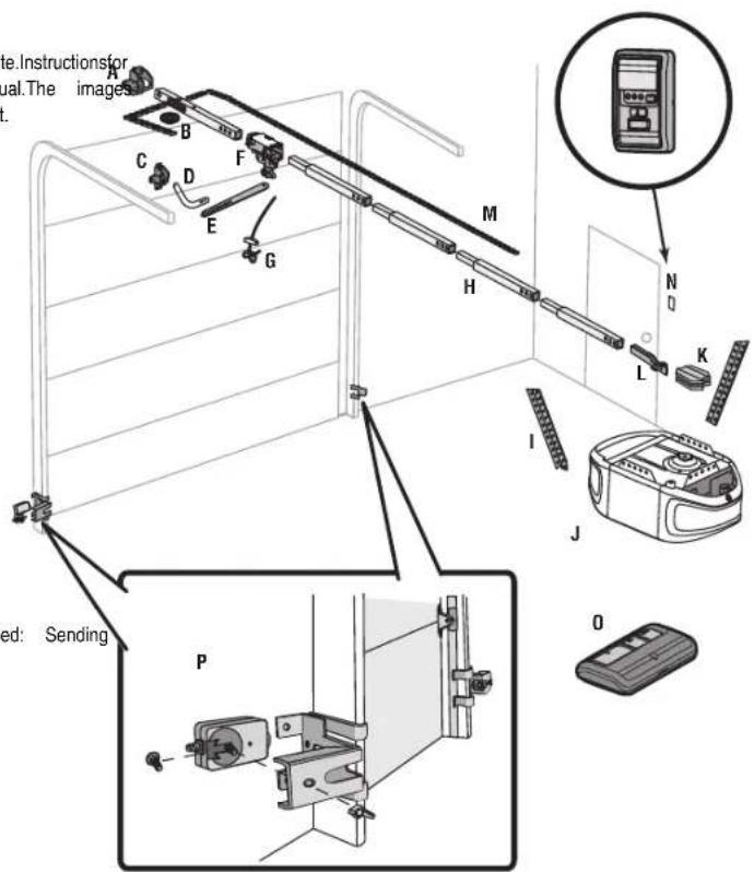
Carton Inventory
Save the carton and packing material until the installation and adjustmentis complete.Instr. the accessories will be attached to the accessory and are notincluded in thismanual.The throughout this manual are for reference only and your product may look different.
| Model | Power | DoorControl | Remote | Control | Wireless | Keypad | |
| C610C | PlusLiftPower | SystemTM | Motion | Detecting | 3-button | (2) | ✓ |
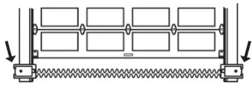
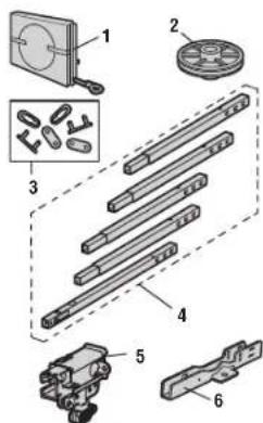
A. Header bracket
B. Pulley
C Door bracket
D. Curved door arm
E. Straight door am (Packaged inside front rail section)
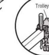
F. Trolley
NOTE: Be sure to assemble the trolley before sliding onto rail.
G. Emergency release rope and handle
H. Rail (1 front and 4 center sections)
I. Hanging brackets (2) (Packaged inside the front rail section)
J. Garage door opener (motor unit)
K. Chain spreader with screws
L. "U" bracket
M. Chain and cable
N. Door control
O. Remote control
P. The ProtectorSystem
Safety reversing sensors with 2 conductor white and white/black wire Sensor (1).Receiving Sensor (1).and SafetySensor Brackets (2)
NOTSHOWN
WirelessKeypad
White and red/white wire
Owner's manual
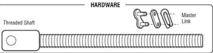
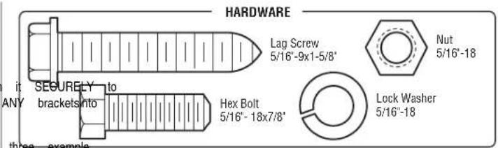
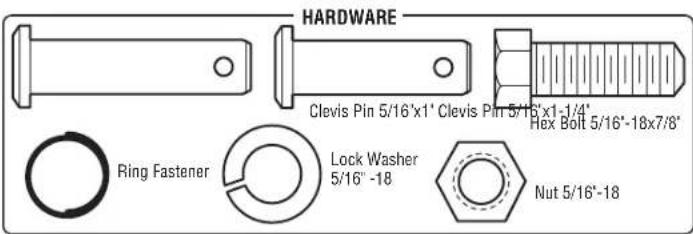
Hardware
Preparation
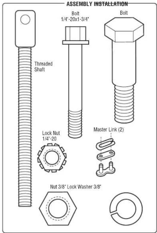
Hardware
Assembly
STEP 1 Assemble the rail and install the trolley
CAUTION
To prevent INJURY from pinching, keep hands and fingers away from the joints while assembling the rail.
To avoid Installationdifficulties, don't run the garage dooropener until instructed to doso.
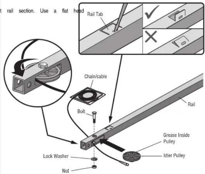
The front rail has a cut out "window" at the door end. The rail tab MUST be on top of the rail when assembled.
- Remove the straight door arm and hanging bracket packaged inside the aside for Installation Step 5 and 9. NOTE: To prevent INJURY while unpacking the rail carefully remove the straight door arm stored within the rail section.
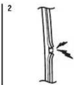
- Align the rail sections on a flat surface as shown and slide the tapered ends into the larger ones. Tabs along the side will lockinto place.
- Place the motor unit on packing material to protect the cover and restthe back of the rail on top. For convenience, put a supportunder the frontend of the rail.
- As a temporary stop, inserta screwdriver into the hole in the second rail section from the motor unit as shown.
- Check to be sure there are 4 plastic wear pads inside the inner trolley. If they became loose during shipping, check all packing material. Snap them back into position as shown.
- Slide the trolleyassembly toward the screwdriver as shown.
- Slide the rail onto the "U" bracket, until it reaches all the stops on the top and sides of the "U" bracket.
end into the larger Rail Tab back top of the rail
section from the motor
In they became loose as shown.
top and sides of the "U"
Slide to stops on top and sides of "U" bracket
Screwdriver
"U" Bracket (TO MOTOR UNIT)
Wear Pads
Front Rail Section (TO DOOR)
Assembly
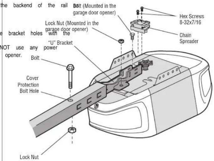
STEP 2 Fasten the rail to the motor unit
CAUTION
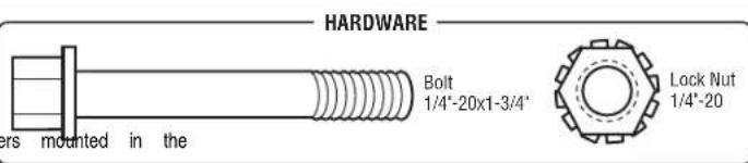
To avoid SERIOUS damage to garage door opener, use ONLY those bolts/fas top of the opener.
- Insert a 1/4^ - 20 x 1 - 3 / 4^ bolt into the cover protection bolt hole on shown.Tighten securely with a 1 / 4^ - 20 locknut. DO NOT overtighten.
- Remove the bolt and lock nut from the top of the motor unit.
3.Use the carton to support the front end of the rail - Place the "U" bracket, flat side down onto the motor unit and align the bolt holes.
- Fasten the "U" bracket with the previouslyremoved bolt and locknut:DO I tools. The use of power tools may permanently damage the garage door
- Attach chain spreader to the motor unitwith two screws.
Assembly
STEP 3 Install the idler pulley
- Lay the chain/cable beside the rail, as shown. Grasp the end of the cable and approximately 12^ (30 cm) of cable through the window. Allow it to hang Step 4.
- Remove the tape from the idler pulley. The inside center should be pre-gr regrease to ensure proper operation.
- Place the idler pulley into the window as shown.
- Insert the idler bolt from the top through the rail and pulley. Tighten and nut underneath the rail until the lock washer is compressed.
- Rotate the pulley to be sure itspins freely.
- Locate the rail tab. The rail tab is near the idler pulley on the front screwdriver and liftthe rail tab until the tab is vertical (90^)
Assembly
STEP 4 Install the chain
WARNING
To avoid possible SERIOUS INJURY to finger from moving garage door opener:
ALWAYS keep hand clear ofsprocket while operating opener.
- Securelyattach sprocket cover BEFORE operating.
-
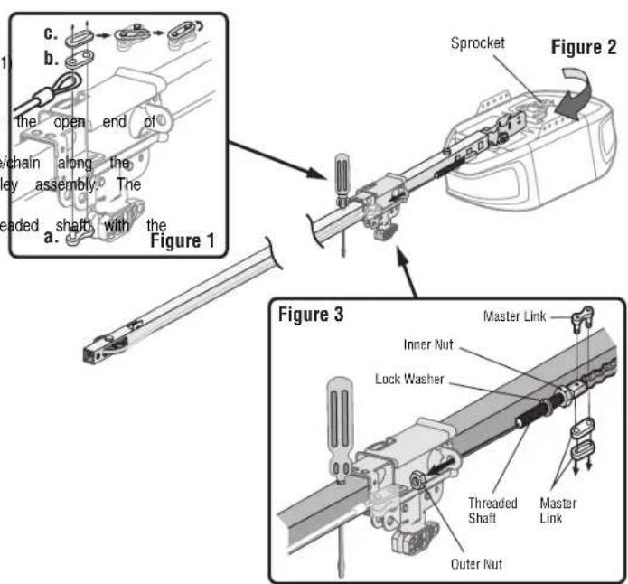
Pull the cable around the idler pulley and toward the trolley.
-
Connect the cable to the retaining slot on the trolley, as shown. (Figure)
a. Push pins of master link bar through cable link and trolley slot.
b. Push master linkcap over pinsand pastpin notches.
c. Slide the closed end ofthe clip-on spring over one ofthe pins.Push
the clip-on spring onto the other pin.
- With the trolley against the screwdriver, dispense the remainder of the car rail toward the motor unit around the sprocket and continuing to the sprocket teeth mustengage the chain. (Figure 2)
- Check to make sure the chain is not twisted, then connect it to the remaining master link.
- Thread the inner nut and lock washer onto the trolley threaded shaft.
- Insert the trolley threaded shaft through the hole in the trolley. Be sure the chain is not twisted. (Figure 3)
- Loosely thread the outer nut onto the trolley threaded shaft.
- Remove the screwdriver.
Assembly
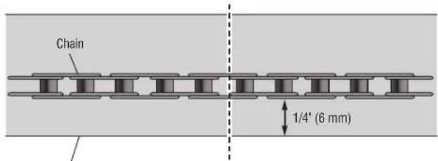
STEP 5 Tighten the chain
- Spin the inner nut and lock washer down the trolley threaded shaft, away from the trolley.
- To tighten the chain, turn the outer nut in the direction shown.
- When the chain is approximately 1 / 4 (6 mm) above the base of the rail at its midpoint,
retighten the inner nut to secure the adjustment.
Sprocket noise can result ifthe chain is too loose.When installation is complete, you may notice some chain droop with the door closed. This is normal. If the chain returns to the position shown when the door is open, do not re-adjust the chain.
NOTE: During future maintenance, ALWAYS pull the emergency release handle to disconnect the trolley before adjusting the chain.
You have now finished assembling your garage door opener. Please read the following warnings before proceeding to the installation section.
Mid length of RailBase of Rail
Installation
| IMPORTANT INSTALLATION INSTRUCTIONS | |
| WARNING | |
| To reduce the risk of SEVERE INJURY or DEATH: | |
| 1. READ ANDFOLLOW ALL INSTALLATION WARNINGS AND INSTRUCTIONS. 9. Install wall-mounted garage door control: | |
| 2. Install garage door opener ONLY on properly balanced and lubricated garage door, within sighttothe garage door. | |
| improperly balanced door mayNOT reverse when required and could result in SEVERE of reach of small children at a minimum heightof5 feet (1.5 m) atinjury or DEATH. | |
| 3. ALL repairs to cables, spring assemblies and other hardware MUST be made by- awaffixed Abbor moving partsof the door. | |
| systems technician BEFORE installing opener. 10. Place entrapment warning label on wall nextto garage door control. | |
| 4. Disable ALL locks and remove ALL ropes connected to garage door BEFORE installangpenerelase/safetyreverse testlabel in plain view on inside ofgarage to avoid entanglement. 12. Upon completion ofinstallation, test safetyreversal system.Do must reverse | |
| 5. Install garage door opener 7 feet (2.13 m) or more above floor. 1-1/2" (3.8 cm) high object (or a 2x4 laid flat) on the floor. | |
| 6. Mount the emergencyrelease within reach,but at least6 feet (1.83 m) above 13the Tiooovaid SERIOUS PERSONAL INJURY or DEATH from electrocution,disconne | |
| avoiding contact with vehicles to avoid accidental release. power BEFORE performing ANY service or maintenance. | |
| 7. NEVER connect garage door opener to power source until instructed to do14.SO DO NOT install on a one-piece door ifusing devices or features providing | |
| 8. NEVER wear watches, rings or loose clothing while installing or servicing openedtoffected codevices and features are to be used ONLY with sectional door be caught in garage door or opener mechanisms. |
Installation
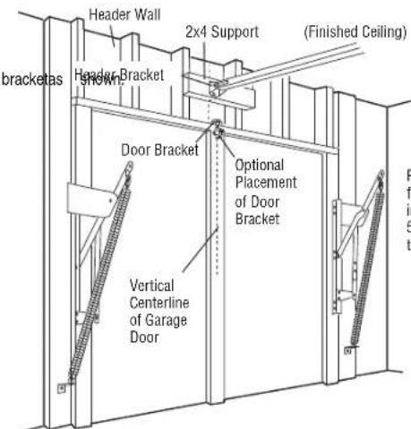
STEP 1 Determine the header bracket location
WARNING
To preventpossible SERIOUS INJURY or DEATH:
- Header bracket MUST be RIGIDLY fastened to structural supporton header wa otherwise garage door might NOT reverse when required.DO NOTinstall header drywall.
Concrete anchors MUST be used if mounting header bracket or 2x4 into m - NEVER try to loosen, move or adjustgarage door, springs,cables,pulleys,brackets, hardware, ALL of which are under EXTREME tension.
ALWAYS call a trained door systems technician if garage door binds, sticks, or is out of balance.
An unbalanced garage door might NOT reverse when required.
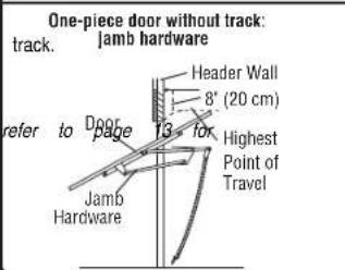
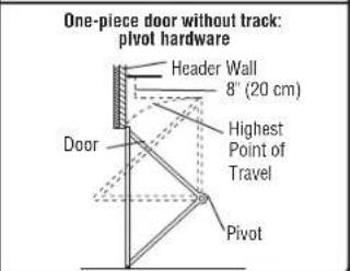
Installation procedures vary according to garage door types. Follow the instructions which door.
- Close the door and mark the inside vertical centerline of the garage door.
- Extend the line onto the header wall above the door. You can fasten the h 4 feet(1.22 m) of the left for right of the door center only if a torsion spring plate is in the way; or you can attach it to the ceiling (see page 13) with (It may be mounted on the wall upside down if necessary, to gain approx you need to install the header bracket on a 2x4 (on wall or ceiling). Use provided) to securely fasten the 2x4 to structural supports as shown here and
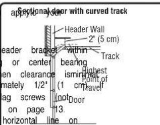
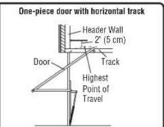
- Open your door to the highest point of travel as shown. Draw an intersecting the header wall 2" (5 cm) above the high point:
2" (5 cm) above the high point for sectional door and one-piece door - 8" (20 cm) above the high pointfor one-piece door withouttrack.
This height will provide travel clearance for the top edge of the door. NOTE: If the total number of inches exceeds the height available in your garage, use the maximum height possible, ceiling installation.
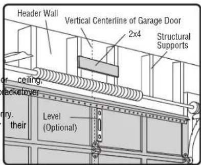
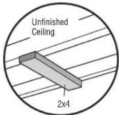
OPTIONAL CEILING MOUNT FOR HEADER BRACKET
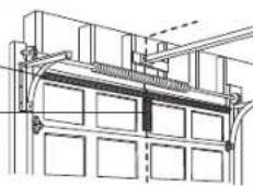
Installation
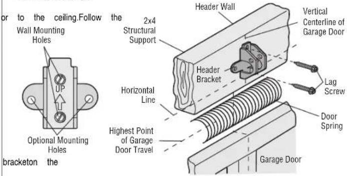
STEP 2 Install the header bracket
You can attach the header bracketeither to the wall above the garage door, instructions which will work best for your particular requirements. Do not Install the header bracket over drywall.If Installinginto masonry,use concrete anchors (not provided).
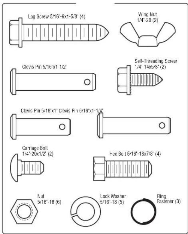
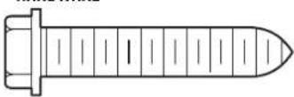
Lag Screw 5/16'-9x1-5/8'
HARDWARE
OPTION A WALL INSTALLATION
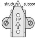
- Center the bracketon the vertical centerline with the bottomedge of the horizontal line as shown (with the arrow pointing toward the ceiling).
- Mark the vertical set of bracket holes.Drill 3/16" pilot holes and fasten structural supportwith the hardware provided.
OPTION B CEILING INSTALLATION
- Extend the vertical centerline onto the ceiling as shown.
- Center the bracketon the vertical mark, no more than 6" (15 cm) from arrow is pointing away from the wall.The bracket can be mounted flush when clearance is minimal.
- Mark the side holes.Drill 3/16" pilot holes and fasten bracket securely to with the hardware provided.
WALL INSTALLATION
CEILING INSTALLATION
the bracket securely to a
the wall. Make sure the against stilling Houing holes
Installation
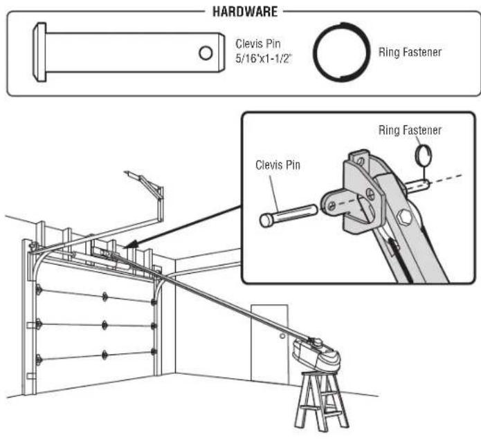
STEP 3 Attach the rail to the header bracket
- Position the opener on the garage floor below the header bracket. Use protective base.
NOTE: If the door spring is in the way, you will need help. Have securely on a temporary support to allow the rail to clear the spring. - Position the rail bracket againstthe header bracket.
- Align the bracketholes and join with a clevis pin as shown.
- Insert a ring fastener to secure.
STEP 4 Position the garage door opener
packing material as a CAUTION
meone hold the opener
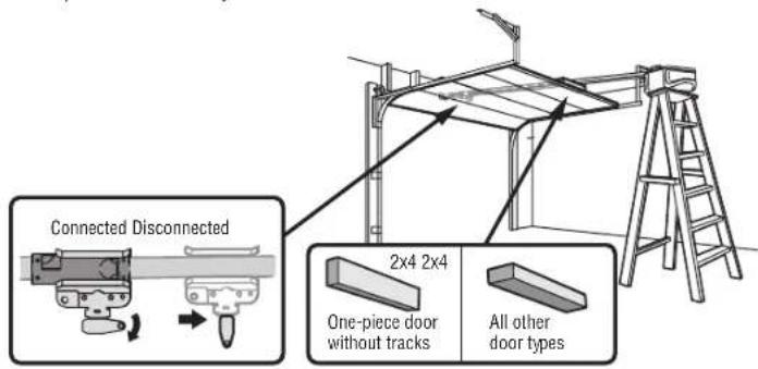
To preventdamage to garage door, rest garage door opener rail on 2x4 placed o door.
- Remove the packing material and liftthe garage door opener onto a ladder.
- Fully open the door and place a 2x4 (laid flat) under the rail. For one-piec tracks, lay the 2x4 on its side.
NOTE: A 2x4 is ideal for setting the distance between the rail and the door. If the ladder is not tall enough you will need help at this point. If the door hits the trolley when it is on release arm down to disconnect the inner and outer trolley. Slide the outer trolley door opener. The trolley can remain disconnected until instructed.
Installation
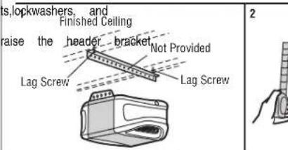
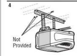
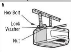
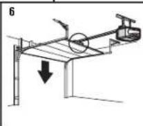
STEP 5 Hang the garage door opener
WARNING
To avoid possible SERIOUS INJURY from a falling garage door opener, fast structural supports of the garage. Concrete anchors MUST be used if installing masonry.
Hanging the garage door opener will vary depending on your garage.Below are installations. Your installation maybe different.For ALL installations the garage door connected to structural supports.The instructions illustrate one of the examples be
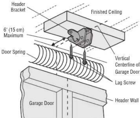
- On finished ceilings,use the lag screwsto attach a support bracket (not provided) structural supports before installing the garage door opener.
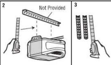
- Make sure the garage door opener is aligned with the header bracket.Measure the from each side offthe garage door opener to the support bracket.
- Cutboth pieces of the hanging bracketo required lengths.
- Attach the end of each hanging bracket to the support bracket with appropriate provided).
- Attach the garage door opener to the hanging brackets with the hexbolts, lockwaste nuts.
- Remove the 2x4 and manually close the door. If the door hits the rail.

opEAMPTST be
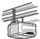
Unfinished Ceiling
Installation
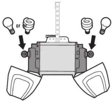
STEP 6 Install the light bulbs
CAUTION
To prevent possible OVERHEATING of the end panel or light socket:
Use ONLY A19 incandescent(100W maximum) or compact fluorescent(26W max) bulbs.
DO NOT use incandescent bulbslarger than 100W.
DO NOT use compact fluorescentlight bulbs larger than 26W (100W equivalent
DO NOT use halogen bulbs.
DO NOT use short neckor specialty lightbulbs.
- Pull on the top sides of the light lensand rotate the light lensdown.
- Insertan A19 incandescent (100W maximum) or compactfluorescent(26W,100W
equivalent) light bulb into the light socket. - Rotate the lens up to close.
NOTE: Do not use halogen, short neck, or specially light bulbs as these may overheat the end panel or
light socket. Do not use LED bulbs as they may reduce the range or performance controls.
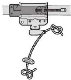
STEP 7 Attach the emergency release rope and handle
WARNING
To prevent possible SERIOUS INJURY or DEATH from a falling garage door:
If eligible, use emergency release handle to disengage trolley ONLY when garag CLOSED. Weak or broken springs or unbalanced door could result in an open rapidly and/or unexpectedly.
NEVER use emergency release handle unlessgarage doorway is clear of persona
obstructions.
NEVER use handle to pull door open or closed. If rope knot becomesuhtied,
- Insertone end of the emergency release rope through the handle. Make sure it is rightside up. Secure with an overhand knot at least 1" (2.5 cm) from the preventslipping.
- Insertthe other end of the emergency release rope through the hole in the Mount the emergency release within reach, but atleast 6 feet (1.83 m) above floor mance contaithwtherticles to prevent accidental release and secure with an overhand
NOTE: If it is necessary to cut the emergency release rope, seal the cutend with a match or lighter to
prevent unraveling. Ensure the emergency release rope and handle are above the to avoid entanglement.
Installation
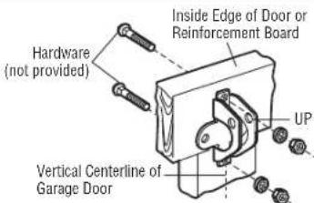
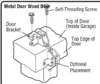
STEP 8 Install the door bracket
CAUTION
Fiberglass, aluminum or lightweight steel garage doors WILL REQUIRE reinforcement BEFORE installation of door bracket.Contactthe garage door manufacturer or installing dealer reinforcement instructions or reinforcement kit.Failure to reinforce the top section according to the door manufacturer may void the door warranty.
A horizontal and vertical reinforcement is needed for lightweight garage doors (steel, doors with glass panel,etc.) (notprovided). A horizontal reinforcement brace is enough to be secured to two or three vertical supports. A vertical reinforcement height off the top panel. Contact the garage door manufacturer or installing dealer. Reinforcement instructions or reinforcement kit.
NOTE: Many door reinforcement kits provide for direct attachment of the clevis pin and door arm. In this case you will not need the door bracket; proceed to the nextstep.
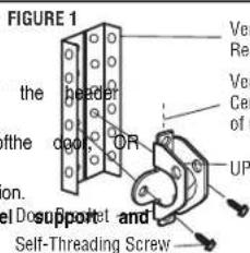
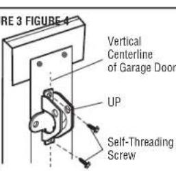
OPTION A SECTIONAL DOORS
- Center the door bracket on the previously marked vertical centerline used bracketinstallation.Note correctUP placement, asstamped inside the bracket.
- Position the top edge of the bracket 2^ - 4^ (5-10 cm) below the top edge directly below any structural support across the top of the door.
- Mark, drill holes and install as follows, depending on your door's consti
Metal orlight weig the door bracket:
- Drill 3 / 16" fastening holes. Secure the door bracket using the two 1 / 4" - 14x5 / 8" self-threading screws. (Figure 1)
- Alternately, use two 5/16" -18x2" bolts, lock washers and nuts (not provided). (Figure 2)
Metal, insulated orlight weight factory reinforced doors:
- Drill 3 / 16^ fastening holes. Secure the door bracket using the self-threading screws. (Figure 3)
Wood doors:
- Use top and bottom or side to side door bracket holes. Drill 5 / 16^ holes through the door and secure bracket with 5 / 16^ - 18x2^ carriage bolts, lockwashers and nuts (not provided). (Figure 4)
NOTE: The 1/4^ - 14 × 5/8^ self-threading screws are not intended for use on wood

for -openera as required
Horizontal Reinforcement
berglass,aluminum,
Vertical Reinforcement
brace should cover the for opener
for the

Installation
STEP 8 Install the door bracket (continued)
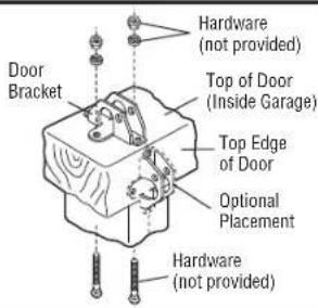
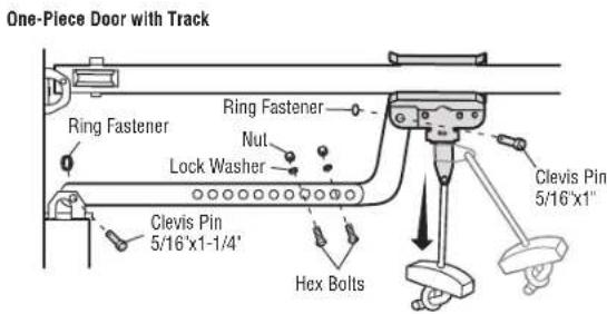
OPTION B ONE-PIECE DOORS
- Center the door bracket on the top of the door, in line with the header
- Mark either the left and right, or the top and bottom holes.
Metal Doors:
- Drill 3/16" pilot holes and fasten the bracket with the self-threading screws provided.
WoodDoors:
Drill 5/16" holes and use 5 / 16^ - 18x2^ carriage bolts, lock washers and nuts (not provided) or
5/16'x1-1/2 lag screws (not provided) depending on your installation needs.
NOTE: The door bracket may be installed on the top edge of the door if required for your installation.
(Refer to the dotted line optional placement drawing.)
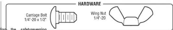
HARDWARE
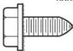
Self-Threading Screw 1 / 4^ - 14x5 / 8^
For a door with no exposed framing, or for the optional installation, use lag screws 5 / 16^× 1 - 1 / 2^ (not provided) to fasten the door bracket.
Installation
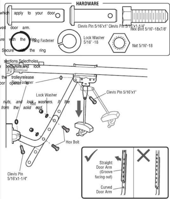
STEP 9 Connect the door arm to the trolley
Installation will vary according to the garage door type. Follow the instructions
OPTION A SECTIONAL DOORS
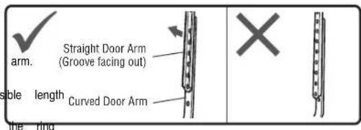
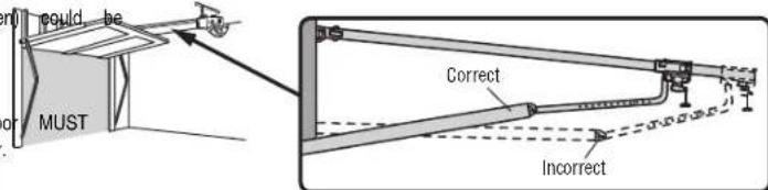
IMPORTANT: The groove on the straightdoor arm MUST face awayfrom the curved
- Close the door. Disconnectthe trolleyby pulling the emergencyrelease handle.
- Attach the straightdoor arm to the outer trolley using the clevispin. Secure fastener.
- Attach the curved door arm to the door bracket using the clevis pin. S fastener.
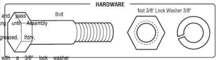
- Bring arm sections together. Find two pairsof holes that line up and join as far apartas possible to increase door arm rigidityand attach using the washers.
- Pull the emergency release handle toward the garage door opener until the arm is horizontal. The trolleywill re-engage automatically when the garage door activated.
NOTE: If the holes in the curved door arm and the straight door arm do not align, reverse the straight door arm, select two holes (as far apart as possible) and attach using bolts, straight door arm is hanging down too far, you may cut 6 inches (15 cm)
Installation
STEP 9 Connect the door arm to the trolley (continued)
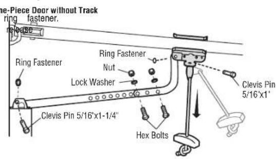
OPTION B ONE-PIECE DOORS
IMPORTANT: The groove on the straight door arm MUST face awayfrom the curved door
- Close the door. Disconnect the trolley by pulling the emergency release handle.
- Fasten the straight door arm and the curved door arm together to the longestpos
(with a 2 or 3 hole overlap) using the bolts,nuts, and lockwashers. - Attach the straight door arm to the door bracket using the clevisin. Secure with
fastener.
4. Attach the curved door arm to the trolley using the clevis pin. Secure with the
5. Pull the emergency release handle toward the garage door opener until
Installation
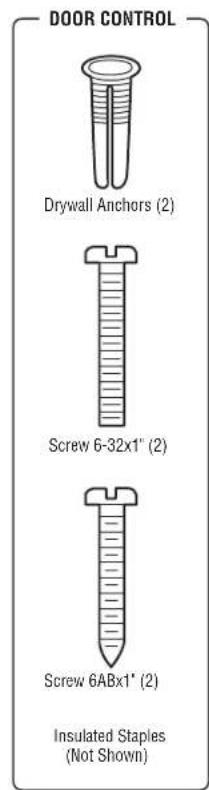
STEP 10 Install the door control
WARNING
To preventpossible SERIOUS INJURY or DEATH from electrocution:
- Be sure power is NOT connected BEFORE installing door control.
- Connectdoor control ONLY to 12 VOLT low voltage wires.
To preventpossible SERIOUS INJURY or DEATHfrom a closing garage door.
Install door control within sight of garage door, out of reach of small children at a minimum height of 5 feet (1.5 m) above floors, landings, steps or any other adjacent away from ALL moving parts of door.
- NEVER permit children to operate or play with door control push button transmitters.
Activate door ONLY when it can be seen clearly, is properly adjusted, obstructions to door travel.
- ALWAYS keep garage door in sight until completely closed. NEVER permit anyone path of closing garage door.
INTRODUCTION
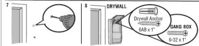
Compatible with Nigabled accessories, see page 41. Your garage door opener up to 2 controls. NOTE: Older Chamberlain door controls and third party products are not compatible.
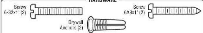
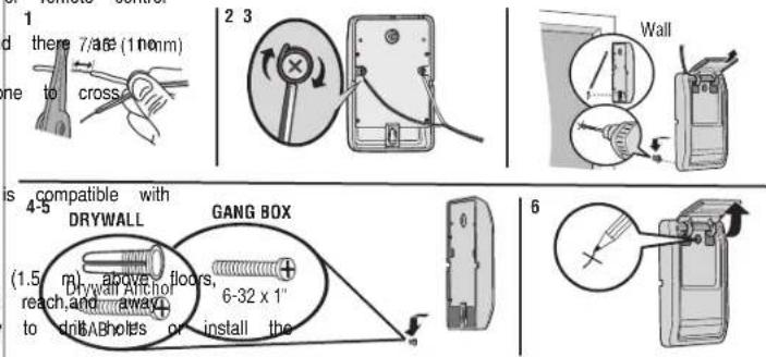
Install the door control within sight of the door at a minimum height of 5 feet landings, steps or any other adjacent walking surface, where small children cannot from the moving parts of the door. For gang box installations it is not necessary drywall anchors.Use the existing holes in the gang box.
NOTE: Your product may look different than the illustrations.
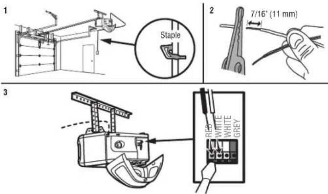
- Strip 7/16 inch (11 mm) of insulation from one end of the wire and separate
- Connect one wire to each of the two screws on the back of the door coil connected to either screw.If your garage is pre-wired for the door control cft wires to connect, note which wires are used so the correctwires are connected door opener in a later step.
- Mark the location of the bottom mounting hole and drill a 5/32 inch hole.
- Install the bottom screw,allowing 1/8 inch (3 mm) to protrude from the wall.
- Position the bottom hole of the door control over the screw and slide down
- Lift the push bar up and mark the top hole.
- Remove the door control from the wall and drill a 5/32 inch hole for the surface and the bottom hole of the door control over the screw and slide dow
or remote the top screw.
Installation
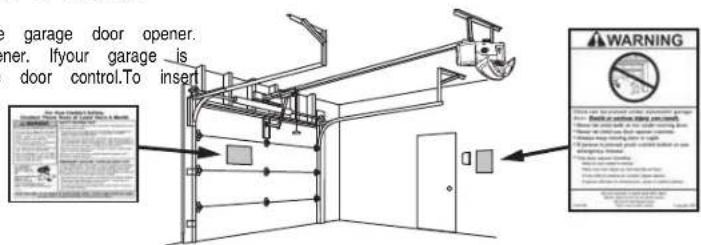
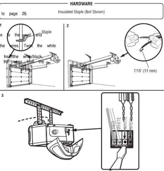
STEP 11 Wire the door control to the garage door oSfep 12 Attach the warning labels
- Run the white and red/white wire from the door control to the garage door. othert h t n the wall near the door control with t wire to the wall and ceiling with the staple (not applicable for gang box atchedthe manual release/safety reverse test label in a visible location on the installations). Do not pierce the wire with the staple as thismaycause a short or gattepedoor.
- Strip 7/16 inch (11 mm) ofinsulation from the end of the wire near the garage door opener.
- Connectthe wire to the red and white terminals on the garage door opener. If your garage is
pre-wired make sure you use the same wires that are connected to the door control.To insert
or release wires from the terminal, push in the tab with screwdriver tip.
HARDWARE
Insulated Staple (Not Shown)
Installation
STEP 13 Install the Protector® System
WARNING
Be sure power is NOT connected to the garage door opener BEFORE install sensor.
To preventSERIOUS INJURY or DEATHfrom closing garage door:
- Correctly connect and align the safety reversing sensor. This required safety device MUST NOT be disabled.
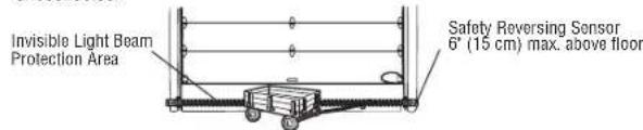
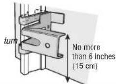
Install the safety reversing sensor so beam is NO HIGHER than 6" (15 cm) above garage floor.
IMPORTANT INFORMATIONABOUT THE SAFETY REVERSING SENSORS
The safety reversingsensors must be connected and alignedcorrectly before the openerwillmove in the down direction.
The sending sensor (with an amber LED) transmits an invisible light beam to a green LED). If an obstruction breaks the light beam while the door is closing, the reverse to the full open position, and the garage door opener lights will flash. NOTE: For energy efficiency the garage door opener will enter sleep mode with closed. The sleep mode shuts the garage door opener down until activated. The sequenced with the garage door opener light bulb; as the light bulb turns off, off and whenever the garage door opener lights turn on the sensor LEDs will opener will not go into the sleep mode until the garage door opener has closed power up.
When installing the safety reversing sensors check the following:
- Sensorsare installed inside the garage,one on either side of the door.
- Sensors are facing each other with the lenses aligned and the receiving sensor lens does not receive direct sunlight.
- Sensorsare no more than 6 inches (15 cm) above the floor and the unobstructed.
Facing the door from inside the garage
The safetyreversing sensors can be attached to the door track, the wall, or the floor.
be no more than 6 inches (15 cm) above the floor. If the door track will not s
wall installation is recommended. Choose one of the following installations.
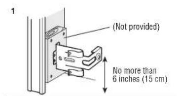
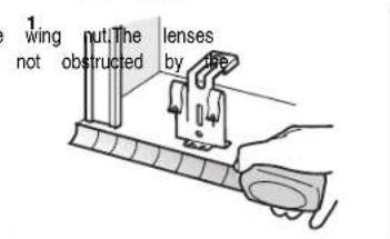
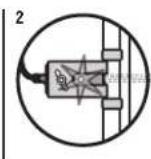
OPTION A DOOR TRACK INSTALLATION
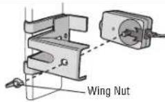
- Slide the curved arms off the sensor bracket around the edge of the door trap place so that the sensor bracket is flush against the track.
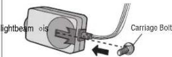
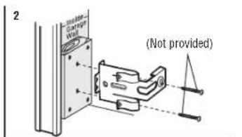
- Slide the carriage boltinto the sloton each sensor.
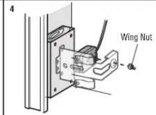
gagda 3. Insert the bolt through the hole in the sensor bracket and attach with the win on both sensors should pointtoward each other. Make sure the lensis not obsl te receiving sensor with sensor bracket
101 times.
en the door is fully.
sleep mode is
the sensor LEDs willlight . The garage doorcompleted 5 cycles upon
2
3
Installation
STEP 13 Install the Protector®(Systemed)
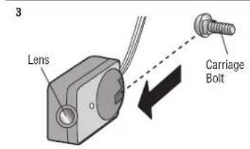
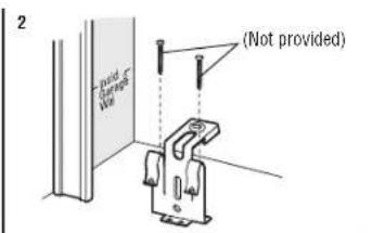
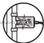
OPTION B WALL INSTALLATION
If additional clearance is needed an extension bracket (not provided) or wood Make sure each bracket has the same amountofclearance so they will align
- Position the sensor bracket against the wall with the curved armsfacing there isenough clearance for the beam to be unobstructed. Markholes.
- Drill 3/16 inch pilot holes for each sensor bracket and attach the sc using lag screws (notprovided).
- Slide the carriage bolt into the slot on each sensor.
- Insert the boltthrough the hole in the sensor bracket and attach with on both sensors should point toward each other. Make sure the lens sensor bracket.
OPTION C FLOOR INSTALLATION
Use an extension bracket (not provided) or wood blockto raise the sensor bracket
1. Carefully measure the position of both sensor brackets so they will be the s blocks caphe wall used unobstructed.
rectly2. Attach the sensor bracketsto the floor using concrete anchors (notprovided). The doorSlidmakthe surbarriage bolt into the slot on each sensor.
4. Insert the bolt through the hole in the sensor bracket and attach with the wire or bracket both the sensors should point toward each other. Make sure the lens is no sensor bracket.

Installation
STEP 14 Wire the Safety Reversing Sensors
If your garage alreadyhas wires installed for the safety reversing sensors, proceed
OPTION A INSTALLATION WITHOUT PRE-WIRING
- Run the wire from both sensors to the garage door opener. Attach the wire ceiling with the staples.
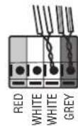
- Strip 7/16 inch (11 mm) of insulation from each set of wires. Separate the wires together. Twist the white/black wires together.
- Insert the white wires into the white terminal on the garage door opener. wires into the greyterminal on the garage door opener.To insert or remove terminal, push in the tab with a screwdriver tip.
Installation
STEP 14 Wire the Safety Reversing Sensors (continued)
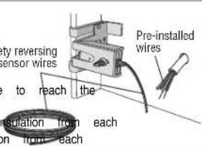
OPTION B PRE-WIRED INSTALLATION
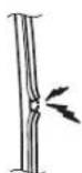
- Cutthe end of the safetyreversing sensor wire, making sure there is enough pre-installed wires from the wall.
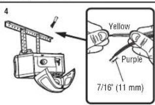
- Separate the safety reversing sensor wires and strip 7/16 inch (11 mm) end.Choose two offhe pre-installed wires and strip 7/16 inch (11 mm) end.Make sure that you choose the same color pre-installed wires for ea
- Connect the pre-installed wires to the sensor wires with wire nuts making correspond for each sensor. For example, the white wire would connect to the white/blackwire would connect to the purple wire.
- At the garage door opener, strip 7/16 inch (11 mm) of insulation from previously chosen for the safety reversing sensors. Twistthe like-colored wire
- Insert the wires connected to the white safety sensor wires to the white door opener. Insertthe wires that are connected to the white/blacksafety se greyterminal on the garage door opener.
1

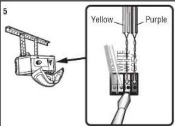
To insert or remove the wires from the terminal, push in the tab with a screwdriver tip.
Installation
STEP 15 Connect power
WARNING
To preventpossible SERIOUS INJURY or DEATHfrom electrocution or fire:
- Be sure power is NOT connected to the opener, and disconnectpower to removing cover to establish permanent wiring connection.
- Garage door installation and wiring MUST be in compliance with ALL local building codes.
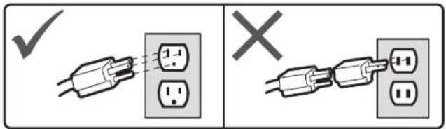
- NEVER use an extension cord, 2-wire adapter, or change plug in ANY way to make it fit outlet. Be sure the opener is grounded.
To avoid installationdifficulties, donot runthe openerat this time.
To reduce the riskof electric shock,your garage door opener has a grounding type grounding pin.Thisplug will only fit into a grounding type outlet. Ifthe plug doesn't have, contact a qualified electrician to install the proper outlet.
THERE ARE TWO OPTIONS FOR CONNECTING POWER:
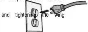
OPTION A TYPICAL WIRING
- Plug in the garage door opener into a grounded outlet.
- DO NOT run garage door opener at this time.
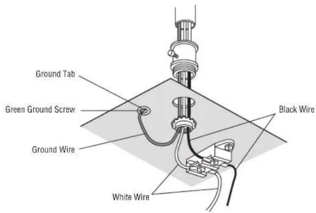
cIOPTIONOREB PERMANENT WIRING
If permanent wiring is required by your local code, refer to the following procedure. If permanent connection through the 7/8 inch hole in the top of the motor unit (code):
- Remove the motor unit cover screws and set the cover aside.
- Remove the attached 3-prong cord.
- Connect the black(line) wire to the screw on the brass terminal; the white
plug screw on the silver terminal; and the ground wire to the green ground sc
inmusthebeoutgrounged.
4. Reinstall the cover.
Installation
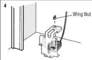
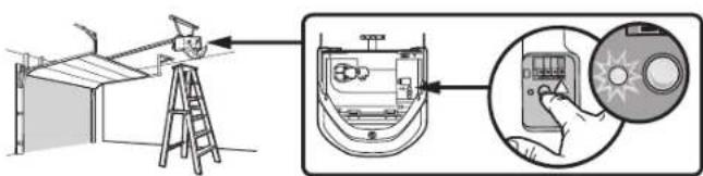
STEP 16 Aligning the safety reversing sensors
The door will not close If the sensors have not been installed andalign When the lightbeam is obstructed or misaligned while the door is closing, the garage door opener lightswill flash ten times.If the door is already open, it will
- Check to make sure the LEDs in both sensors are glowing steadily. will glow steadily if they are aligned and wired correctly. The sensors can be aligned by loosening the wing nuts, aligning the sensor nuts.
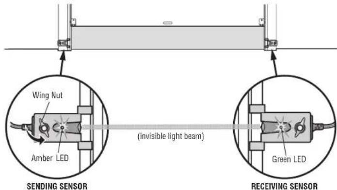
If the receiving sensor is in direct sunlight, switch it with sending sensor so it is on the opposite side of the door.
IF THE AMBER LED ON THE SENDING SENSOR IS NOT GLOWING:
- Make sure there is power to the garage door opener.
edcorrecty. Make sure the sensor wire is not shorted/broken.
door wall Make sure the sensor has been wired correctly:white wires to white terminal
not close.wires to grey terminal.
theLEpsinboth sensors
3
IF THE GREEN LED ON THE RECEIVING SENSOR IS NOT GLOWING:
-
Make sure the sensor wire is not shorted/broken.
-
Make sure the sensors are aligned.
1
STEP 17 Ensure the door control is wired correctly
If the door control has been installed and wired correctly, the command LED on the Control Panel will blink.
Adjustments
Introduction
| WARNING |
| Without a properly installed safetyreversal system, persons (particularly small ch SERIOUSLY INJURED or KILLED by a closing garage door. Incorrect adjustment of garage door travel limits will interfere with proper operation of safety reversal system. After ANY adjustmentsare made,the safety reversal system MUST be tested. reverse on contactwith 1-1/2" (3.8 cm) high object(or 2x4 laid flat) on t |
CAUTION
To prevent damage to vehicles, be sure fully open door provides adequate
Your garage door opener is designed with electronic controls to make setup and adjustments allow you to program where the door will stop in the open (UP) position. The electronic controls sense the amount of force required to open a force is adjusted automatically when you programthe travel.
NOTE: If anything interferes with the door's upward travel it will stop. If anything interferes with the door's downward travel, it will reverse.
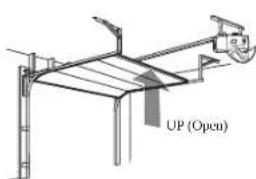
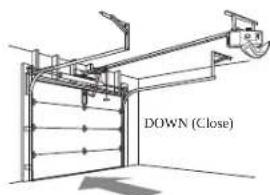
One-Piece Doors Only
When setting the UP travel for a one-piece door ensure that the door does not slant fully open (UP). If the door is slanted backwards this will cause unnecessary bucking when the door is opening or closing.
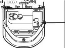
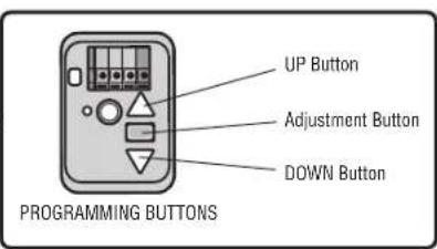
Programming Buttons
The programming buttons are located on the left side panel of the garage door opera program the travel. While programming, the UP and DOWN buttons can be used to
and, close (DOWN)
Adjustments
STEP 1 Program the Travel
WARNING
Without a properly installed safetyreversal system, persons (particularly small children) SERIOUSLY INJURED or KILLED by a closing garage door.
Incorrect adjustment of garage door travel limits will interfere with proper operation of safety reversal system.
After ANY adjustments are made, the safety reversal system MUST be tested. Do reverse on contact with 1 - 1 / 2^n (3.8 cm) high object(or 2x4 laid flat) on floor.
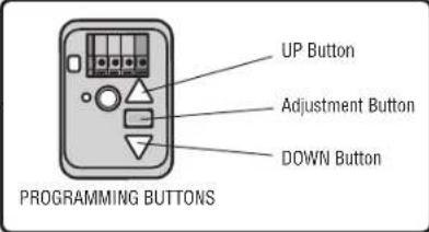
While programming, the UP and DOWN buttons can be used to move the door 1 as needed
- Pressand hold the Adjustment Button until the UP Button begins to flash and/or a deep
- Pressand hold the UP Button until the door is in the desired UP position.
- Once the door is in the desired UP position press and release the Adjustment Button. The garage door opener lights will flash twice and the DOWNButton will begin to flash
IMPORTANT NOTE: For one-piece door installations refer to page 29.
- Pressand hold the DOWNbutton until the door is in the desired DOWN
- Once the door is in the desired DOWN position press and release the Adjustment Button.
garage door opener lights will flash twice and the UP Button will begin to flash. - Pressand release the UP Button.When the door travelsto the programmed UP position,the DOWN Button will begin to flash.
- Pressand release the DOWN Button.The door will travel to the programmed DOWNposition. Programming is complete.
If the garage door opener lights are flashing 5 times during the steps for Pr programming has timed out. If the garage door opener lights are flashing 10 Program the Travel, the safetyreversing sensors are misaligned or obstructed (refer the sensors are aligned and unobstructed, cycle the door through a complete the remote control or the UP and DOWN buttons. Programming is complete. If operate the door up and down, repeat the stepsfor Programming the Travel.
gram the Travel , thetimesduring the stepsfordto page 28.Whenup and down cycle onyou are unable to

To watch a video, go to tinyurl.com/kkwbnhj
5
Adjustments
STEP 2 Test the Safety Reversal System
WARNING
Without a properly installed safetyreversal system, persons (particularly small child) SERIOUSLY INJURED or KILLED by a closing garage door.
-
Safety reversal system MUST be tested every month.
After ANY adjustments are made, the safety reversal system MUST be tested. reverse on contactwith 1 - 1 / 2^n (3.8 cm) high object(or 2x4 laid flat) on In -
With the door fully open, place a 1-1/2 inch (3.8 cm) board (or a centered under the garage door.
- Pressthe remote control push button to close the door. The door MUST makes contact with the board.
If the door stops and doesnotreverse on the obstruction, increase the down travel Step 1).Repeatthe test.When the door reversesupon contact with the 1-1/2 inch board and open/close the door 3 or 4 times to test the adjustment.If the ga to fail the safety reversal test, call a trained door systems technician.
STEP 3 Test the Protector® System
WARNING
I would be properly installed safetyreversing sensor, persons (particularly small children) SERIOUSLY INJURED or KILLED by a closing garage door.
Door 1 MUpen the door. Place the garage door opener carton in the path offthe do floor: Pressthe remote control push button to close the door.The door will notmove inch (2.5 cm), and the garage door opener lights will flash 10 times.
The laid garde door the open floor will notclose from a remote control if the LEDin either is off (alerting you to the factthat the sensor is misaligned or obstructed).If the ga close when door when the safety reversing sensor is obstructed (and the sensorsare 6 inches [15 cm]above the floor),call for a trained door systemtechnician.
Operation
IMPORTANT SAFETY INSTRUCTIONS
WARNING
To reduce the risk of SEVERE INJURY or DEATH:
- READ ANDFOLLOW ALL WARNINGS ANDINSTRUCTIONS.
- ALWAYS keep remote controls out of reach of children. NEVER permit children play with garage door control push buttons or remote controls.
- ONLY activate garage door when it can be seen clearly, it is properly adjusted, obstructions to door travel. 11
- ALWAYS keep garage door in sight and away from people and objectsuntil NO ONE SHOULD CROSS THE PATHOF THE MOVING DOOR.
- NO ONE SHOULD GO UNDER A STOPPED, PARTIALLY OPENED DOOR.
- If possible, use emergency release handle to disengage trolley ONLY when CLOSED. Use caution when using this release with the door open. Weak unbalanced door could result in an open door falling rapidly and/or unexpected the riskof SEVERE INJURY OR DEATH.
- NEVER use emergency release handle unless garage doorways clear of persons obstructions.
- NEVER use handle to pull garage door open or closed. Ifrope knot become fall.
After ANY adjustments are made, the safetyreversal system MUST be tested. Safepersabr system MUST be tested every month. Garage door MUST revers with 1-1/2" (3.8 cm) high object(or a 2x4 laid flat) on the floor. Failure to
andodtherpeper properly increases the riskof SEVERE INJURY or DEATH. 11.ALWAYS KEEP GARAGE DOOR PROPERLY BALANCED (see page 2).An ir completed door may NOT reverse when required and could result in SEVERE DEATH.
12. ALL repairs to cables, spring assemblies and other hardware, ALL of which are
arageExTeRMb tension, MUSTbe made by a trained door systems technician. 13.broWAYgsconect electric power to garage door opener BEFORE making AN andentmoing sivovers.
14. This operator system is equipped with an unattended operation feature. The c andunexpectcdy.NO ONE SHOULD CROSS THE PATHOF THE MOVING DOOR. 15. DO NOT install on a one-piece door if using devices or features providing suntiednattendoutdevicestand features are to be used ONLY with sectional doors.
16. SAVE THESE INSTRUCTIONS.
Operation
Features
Your garage door opener is equipped with features to provide you with greater garage door operation.
MyQ®
MyQ® technology uses a 900MHz signal to provide two-way communication between opener and MyTabled accessories. Your garage door opener is compatible with accessories. For Smartphone App control of your garage door open@accessorether Chamberlain's MyInternet Gateway (model CIGBUC) is required.
TIMER-TO-CLOSE (TTC)
The Timer-to-Close feature automatically closes the garage door after a specified time period. DO NOT enable TTC if operating a one-piece door. TTC is tobe used ONLY with default is set to off. The garage door opener will beep and the lights will be The TTC feature will deactivate if the garage door encounters an obstruction or reversing sensors are incorrectly installed. The garage door will reverse open as until the obstructions are clear or the safetyreversing sensors are correctly instobstruction has been cleared or the safetyreversing sensors have been aligned, when the garage door opener isactivated. TTC WILL NOT workif the garage by battery power or ifthe safety reversing sensors are misaligned. Thisfeature is the primary method of closing the door. A keyless entry should be installel accidentallock out when using this feature.
REMOTE CONTROLS AND DOOR CONTROLS (MyQ
Your garage door opener has already been programmed at the factory to op control, which changes with each use, randomly accessing over 100 billion new MyQ®enabled accessories, see page 41.
NOTE: Older Chamberlain remote controls, door controls, and third party products are not compatible.
| MyQ®Accessories | MEMORY | CAPACITY | |||||||||
| Remote | Controls | Up | to | 8 | |||||||
| Door | Controls | Up to | 2 | ddopa | controls | ||||||
| KeylessEntries | Up | to | 1 | ||||||||
THE PROTECTOR SYSTEM SAFETY REVERSING SENSORS)
When properly connected and aligned, the safety reversing sensors will detect an oth path of the infrared beam. If an obstruction breaks the infrared beam while the door will stop and reverse to full open position, and the opener lightswill flash 10 time open, and the safety reversing sensors are not installed, or are misaligned, the do the manage control.However,you can close the door ifyou hold the button on the door uantio. until Mydoor is fully closed. The safety reversing sensorsdo not effectthe open EENERGY CONSERVATION
For energy efficiency the garage door opener will enter sleep mode when the door sleep mode shuts the garage door opener down until activated. The sleep mode isgaragedoor opener light bulb; as the light bulb turns off the sensor LEDswill turnsegaledeed . deryf y lightsturn on the sensor LEDswill light .The garagedoor opener 'shetbeep cleard e till d . garagedoor opener has completed 5 cyclesupon power u
wiche is safe id wihl NOT cso
The garer the door opener light bulbs will tum on when the opener is initially plugged
the restored after clepruption, or when the garage door opener is activated. The lightswi
ocutepically is after 1/2 minutes. An incandescent A19 light bulb (100 wattmaximum)
Nenerterie ci ene be 26W (100W equivalent) compactfluorescent light (CFL) bulb may be
The nove f aloan short neck, or specialty light bulbs as these may overheat t
socket. Do not use LED bulbs as they may reduce the range or performance of
Light Feature
The safetyreversing sensor infrared beam is added control over the light bulbs on your garage door opener, see page 34.
Operation
Using your Garage Door Opener
The garage door opener can be activated through a wall-mounted door control, wirelesskeyless entryor MyAccessory.
When the door is closed and the garage door opener is activated the door is an obstruction or is interrupted while opening the door will stop. When the door is not closed and the garage door opener is activated the door will close. If the doors are senses an obstruction while closing, the door will reverse. If the obstruction interrupts the garage door opener lightwill blink 10 times. However, you can close the door on the door control or keyless entryuntil the door is fully closed.
The safety reversing sensors do not affect the opening cycle. The safety reversing s connected and aligned correctly before the garage door opener will move in th
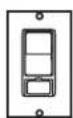
Motion Detecting Control Panel
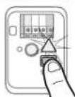
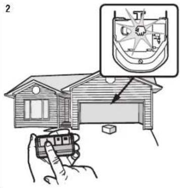
SYNCHRONIZE THE DOOR CONTROL
To synchronize the door control to the garage door opener, press the push bar opener activates (it may take up to 3 presses). Test the door control by pressing press of the push bar will activate the garage door opener.
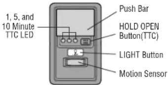
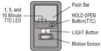
MOTION DETECTING CONTROL PANEL FEATURES
PUSH BAR
Press the push bar to open or close the door.
will open. If the door senses
LIGHTS or is in any position other
garage door opener Press the sensor light button to turn the garage door opener lightson or off. When the they will stay on the LIGHT button is pressed again, or until the garage door Once the garage door opener is activated the lightswill tum offafter the specified p factory setting is 4-1/2 minutes).The LIGHTbutton will not control the lightswhen the
To change the amount of time the garage door opener lights will stay on:
Press and hold the LOCK button (approximately 10 seconds) until the garage door
The time interval is indicated by the number times the garage door opener flashes
1 flash is 1-1/2 minutes
2 flashes is 2-1/2 minutes
the flagrate is dogr1/2 minutes
push bar, each 4-1/2 minutes
To cycle through the time intervals repeatthe step above.
Light Feature
The lightswill turn on when someone enters through the open garage door and the sensor infrared beam is broken.
- Deactivate: Press and hold the LIGHT button (approximately 10 seconds) until the garage door opener lightstum on, then offagain.
- Activate: Start with the garage door opener lights on. Press and hold the LIGHT button
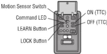
(approximately 10 seconds) until the garage door opener lightsturn off, then c If the command LED is continuouslyblinking, the LOCK feature needs to be deactiva Motion Sensor
Factory default is set to on. Thisfeature automatically turns on the garage door op. motion is sensed. The lightswill come on for the setperiod of time, then shut off. I opener light as a work light disable the motion sensor, otherwise the light will turn are beyond the range of the sensor.
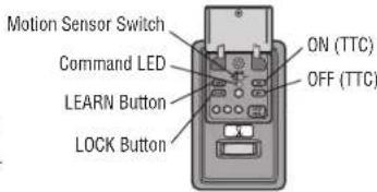
Activate/Deactivate: Slide the motion sensor switch ON or OFF.
Operation
Motion Detecting Control Panel (continued)
LOCK
The LOCK feature is designed to prevent activation of the garage door opener while still allowing activation from the door control and keyless entry. This feature is a peace of mind when the home is empty (i.e. vacation).
Activate: Press and hold the LOCK button for 2 seconds. The command LED will flash as long as the lockfeature is activated and your handheld remote control door at this time.
- Deactivate: Press and hold the LOCK button again for 2 seconds. The command LED will stop flashing and normal operation will resume.
TIMER-TO-CLOSE
DO NOT enable TTC if operating a one-piece door. The TTC can be turned off, the interval can be adjusted to 1, 5, and 10 minute intervals. Once the TTC has been open, the selected close interval will blink and begin to count down to close it.
- Activate: Press and hold the ON button until one of the TTC LEDs light up. Then press the ON button again to cycle through the time interval options (the color light for each time interval). The garage door opener light bulbs will
- Deactivate: Press and hold the OFF button until all TTC LEDs turn off and a beep is heard from the motor unit.
- Temporarily hold door open (suspend TTC): Press and release the HOLD OPEN button. Press the HOLD OPEN button again to resume normal TTC operation
PROGRAM
Any compatible remote controls, wireless the garage door opener by pressing
keylessentryAccedyies can be programmed the Learn button.
Remote Control and Keyless Entry
Pre-programed remote control included, no need to program the remote.
ToaddRemote represeem a remote control, follow the instructions below.Older Chamberlain
contralsetare for NCoded compatible, see page 41 for compatible accessories.
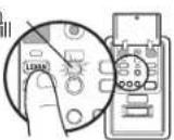
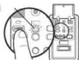
PROGRAM USING THE DOOR CONTROL
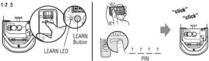
- Press the LEARN button on the door control to enter Programming Mode.
- Press the LEARN button again, the LED will flash once.
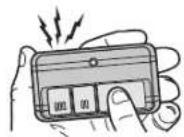
- Remote Control: Press the button on the remote control that you wish to operate your garage door.
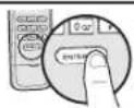
Keyless Entry: Enter a 4-digit personal identification number (PIN) of your cl keyless entry, keypad. Then presthe ENTER button.
Thee eaege aegr theepener lightswill flash (or two clicks will be heard) when the con
The command LED will flash once as confirmation.
2 The command LED will flash once again.
3
OR
?PIN
Operation
Remote Control (continued)
PROGRAM USING THE LEARN BUTTON
- Locate the Learn Button.
- Press and immediately release the Learn button. The Learn LED will seconds.Within 30 seconds...
- Remote Control: Press and hold the button on the remote control that you wish to use. Keyless Entry: Enter a 4-digit personal identification number (PIN) of keyless entrykeypad. Then press and hold the ENTER button.
Release the button when the garage door opener lights blink or two clicks are the light lens cover, ensure the antenna wires are hanging straight down.

To watch a video, go to tinyurl.com/lsf6xt
HomeLink
If your vehicle is equipped with HomeLink, a CaffiscityBridge may be necessary for certain vehicles. Visit bridge.chamberlain.com to find out ifa Bridge is needed.
To Erase the Memory
ERASE ALL REMOTE CONTROLS AND KEYLESS ENTRIES
- Press and hold the LEARN button on garage door opener until the learn LE stead (approximately 6 seconds). All remote control and keylessentrycodes are now era Reprogram any accessory you wish to use.
ERASE ALL THE DEVICES (Including dMgDed accessories)
- Press and hold the LEARNbutton on garage door opener until the learn LE (approximately 6 seconds).
- Immediately press and hold the LEARNbutton again until the learn LED goes are now erased. Reprogram any accessory you wish to use.
Operation
To Open the Door Manually
WARNING
To prevent possible SERIOUS INJURY or DEATHfrom a falling garage door:
If possible, use emergency release handle to disengage trolley ONLY when garage door is CLOSED.Weak or broken springs or unbalanced door could result in an open door falling rapidly and/or unexpectedly.
NEVER use emergency release handle unlessgarage doorway is clear of persons and obstructions.
NEVER use handle to pull door open or closed. Ifrope knot becomesuntied, you could fall.
- The door should be fully closed if possible.
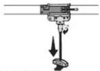
- Pull down on the emergencyrelease handle so the trolley release arm snaps to the vertical
position. The door can now be raised and lowered as often as necessary.
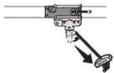
- Pull the emergency release handle toward the garage door opener so the trolley release arm snaps to the horizontal position. The trolley will reconnect the next UP or DOWN operation, either manually or by using the door control or remote control.
Maintenance
Maintenance Schedule
EVERYMONTH
- Manually operate door. If it is unbalanced or binding, call a trained door systems technician.
Check to be sure door opens and closesfully. Adjust if necessary, see page
Test the safetyreversal system. Adjust if necessary, see page 31.
EVERY YEAR
- Oil door rollers, bearings and hinges. The garage door opener does not require lubrication. Do not grease the door tracks.
The Remote Control Battery
WARNING
To prevent possible SERIOUS INJURY or DEATH:
NEVER allow small children near batteries.
If battery is swallowed, immediately notify doctor.
To reduce risk of fire, explosion or chemical burn:
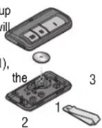
- Replace ONLY with 3V CR2032 coin batteries.
DO NOT recharge, disassemble, heat above 212^ (100^) or incinerate.
The 3V CR2032 Lithium battery should produce power for up to 3 years.If the battery is low, the remote control's LED will not flash when the button is pressed.
To replace battery, pry open the case first in the middle (1), then at each side (2 and 3) with the visor clip. Replace batteries with only 3V CR2032 coin cell batteries. Insert battery positive side up. Dispense of old batteries properly.
NOTICE: This device complies with Part 15 of the FCC rules and Industry Canada's license-ex Operation is subject to the following two conditions: (1) this device may not cause harmful int device must accept any interference received, including interference that may cause undesired ope Any changes or modifications not expressly approved by the party responsible for compliance co authority to operate the equipment.
2This device must be installed to ensure a minimum 20 cm (8 in.) distance is maintained between and device. This device has been tested and found to comply with the limits for a Class B digital device against harmful interference in a residential installation. This equipment generates, uses and can generate energy and, if not installed and used in accordance with the instructions, may cause radio communications. However, there is no guarantee that interference will not occur in a device that does cause harmful interference to radio or television reception, which can be turning the equipment off and on, the user is encouraged to try to correct the interference by following measures:
Reorient or relocate the receiving antenna.
- Increase the separation between the equipment and receiver.
Connect the equipment into an outlet on a circuit different from that to which the receiver is connected.
Consult the dealer or an experienced radioTV technician for help.
Your garde door opener is programmed with self-diagnostic capabities. The UP and DOWN arrows on the garage door opener flash the diagnostic codes.
| DIAGNOSTIC CODE SYMPTOM SOLUTION | |||
| Up Arrow Flash(es) | Down Arrow Flash(es) | ||
| 1 | 1 | The garage door opener will not close and the light bulbs flash. | Safety reversing sensors are not installed, connected, or wires may be cut. Inspect sensor wires for a disconnected or cutwire. |
| 1 | 2 | The garage door opener will not close and the light bulbs flash. | There is a short or reversed wire for the safety reversing sensors. Inspect safety sensor wire at all staple and connection points, replace wire or correctas needed. |
| 1 | 3 | The door control will not function. | The wires for the door control are shorted or the door control is faulty. Inspect door control wires at all staple and connection points, replace wire or correctas needed. |
| 1 | 4 | The garage door opener will not close and the light bulbs flash. | Safety reversing sensors are misaligned or were momentarily obstructed. Realign both sensors to ensure both LEDsare steady and not flickering. Make sure nothing is hanging that would interrupt the sensor's path while closing. |
| 1 | 5 | Door moves 6-8" (15-20 cm) stops or reverses. | Manually open and close the door. Check for binding or obstructions, such as a broken spring or door lock, correctas needed. Checkwiring connections at travel module and at the lo travel module if necessary. |
| No movement, only a single click. | Manually open and close the door. Check for binding or obstructions, such as a broken spring or door lock, correctas needed. Replace logic board if necessary. | ||
| Opener hums for 1-2 seconds no movement. | Manually open and close the door. Check for binding or obstructions, such as a broken spring or door lock, correctas needed. Replace motor ifnecessary. | ||
| 1 | 6 | Door coats after it has come to a complete stop. | Program travel to coasting position or have door balanced by a trained door systems technician. |
| 2 | 1-5 | No movement, or sound. Replace logic board. | |
| 3 | 2 | Unable to set the travel or retain position. | Check travel module for proper assembly, replace if necessary. |
Troubleshooting
| DIAGNOSTIC CODE SYMPTOM SOLUTION | |||
| Up Arrow Flash(es) | Down Arrow Flash(es) | ||
| 4 1-4 | Door is moving stops or reverses. | Manually open and close the door. Check for binding or obstructions, such as a broken spring or door lock, correct as needed. If the door isbinding or sticking contact a trained door system is not binding or sticking attempt to reprogram travel (refer to page 30). | |
| 4 | 5 | Openers runs approximately 6-8" (15-20 cm), stop communication error to travel module. Check travel module connections, replace travel mode necessary. | |
| 4 | 6 | The garage door opener will notclose and the flash. | Slightly本市ing sensors are misaligned or were momentarilyobstructed. Realign both sensors both LEDs are steady and not flickering. Make sure nothing is hanging or mounted or interruptthe sensor's path while closing. |
The garage door openercanbeep forseveralreasons:
- Garage door opener has been activated through a device or feature such as Timer-to-Close or garage door monitor, see page 33.
My remote controlwill not activate the garage door:
- Verify the lockfeature isnot activated on the door control.
- Reprogram the remote control.
- If the remote control will still not activate the door check the diagnostic codes to ensure the garage door opener is working properly.
My door will not close and the light bulbs blink on my motor unit:
The safety reversing sensor must be connected and aligned correctly before will move in the down direction.
- Verify the safety reversing sensors are properly installed, aligned and free of any obstructions.
My garage door openerlight(s) willnot turn off whenthe doors open:
The garage door opener is equipped with a feature that turns the light on when the sensors have been obstructed or when the motion sensor on the door control detects garage. These features can be disabled using the door control, see page page 34.
My neighbor's remote control opens my garage door:
Erase the memory from your garage door opener and reprogram the remote control(s);
My vehicle's Hom@link not programming to my garage door opener:
Compatibility Bridge (notincluded) may be necessary for certain vehicles. Visit
bridge.chamberlain.com to find outif a Bridge isneeded.
e garage door opener
Accessories
7708CB

8 Foot (2.4 m) Rail
Extension:
To allow an 8 foot (2.4 m) door to open fully.
041A5281-1 Extension Brackets:

(Optionai) For safety reversing sensor installation onto the wall or floor.
940EVC Wireless Keypad:

For use outside of the home to enable access to the garage using a 4-digit PIN. Works with ALL Chamberlain openers from 1993-present. MyQ compatible.
953EVC

Remote Control:
Works with ALL Chamberlain openers from 1993-present. MyQ compatible. Includes visor clip.
7710CB

10 Foot (3 m) Rall Extension:
To allow a 10 foot (3 m) door to open fully.
CLLP1 Laser Parking Assistant:

Park in the right spot every time! A laser beam is activated by your garage door opener and projected on to the dashboard of your vehicle to guide perfect parking.
956EVC Keychain Remote Control:

Works with ALL Chamberlain openers from 1993-present. MyQ compatible. With key ring.
MyQ® Accessories
PILCEVC MyQ Remote Lamp Control:

in lamp switch with the MyQ Smartphone App.
WSLCEVC MyQ 念 Interior/Exterior Light
Switch Monitor and control this wall light switch with the MyQ Smartphone App.
CIGBUC

MyQ® Internet Gateway: Offers longer range wireless signal than standard Wi-Fi. Plugs into your home router as an optional way to provide MyQ® Smartphone Control for your garage door opener and MyQ® light controls.
Warranty
STOP!
This garage door opener WILL NOT work until the safety reversing sensors are properly installed and aligned.
Contact Information
For installation and service information:
www.chamberlain.com
1-800-528-9131
Before calling, please have the model number of the garage door opener.
If you are calling about a Troubleshooting issue, it is recommended that you have access to your garage door opener while calling.
If you are ordering a repair part please have the following information:
part number, part name, and model number.
CHAMBERLAIN® LIMITED WARRANTY
The Chamberlain Group, Inc. ("Seller") warrants to the first retail purchaser of this product, for the residence in which this product is originally installed, that it is free from defects in materials and/or workmanship for a specific period of time as defined below (the "Warranty Period"). The warranty period commences from the date of purchase.
| WARRANTY PERIOD | ||
| Parts Motor Chain Accessories | ||
| 5 Years Lifetime 5 Years 1 Year | ||
The proper operation of this product is dependent on your compliance with the instructions regarding installation, operation, and maintenance and testing. Failure to comply strictly with those instructions will void this limited warranty in its entirety. If, during the limited warranty period, this product appears to contain a defect covered by this limited warranty, call 1-800-528-9131, toll free, before dismantling this product. You will be advised of disassembly and shipping instructions when you call. Then send the product or component, pre-paid and insured, as directed to our service center for warranty repair. Please include a brief description of the problem and a dated proof-of-purchase receipt with any product returned for warranty repair. Products returned to Seller for warranty repair, which upon receipt by Seller are confirmed to be defective and covered by this limited warranty, will be repaired or replaced (at Seller's sole option) at no cost to you and returned pre-paid. Defective parts will be repaired or replaced with new or factory rebuilt parts at Seller's sole option. [You are responsible for any costs incurred in removing and/or reinstalling the product or any component.]
ALL IMPLIED WARRANTYES FOR THE PRODUCT, INCLUDING BUT NOT LIMITED TO ANY IMPLIED WARRANTYES OF MERCHANTABILITY AND FITNESS FOR A PARTICULAR PURPOSE, ARE LIMITED IN DURATION TO THE APPLICABLE LIMITED WARRANTY PERIOD SET FORTH ABOVE FOR THE RELATED COMPONENT(S), AND NO IMPLIED WARRANTY WILL EXIST OR APPLY AFTER SUCH PERIOD. Some States and Provinces do not allow limitations on how long an implied warranty lasts, so the above limitation may not apply to you. THIS LIMITED WARRANTY DOES NOT COVER NON-DEFECT DAMAGE, DAMAGE CAUSED BY IMPROPER INSTALLATION, OPERATION OR CARE (INCLUDING, BUT NOT LIMITED TO ABUSE, MISUSE, FAILURE TO PROVIDE REASONABLE AND
NECESSARY MAINTENANCE, UNAUTHORIZED REPAIRS OR ANY ALTERATIONS TO THIS PRODUCT), LABOR CHARGES FOR REINSTALLING A REPAIRED OR REPLACED UNIT, REPLACEMENT OF CONSUMABLE ITEMS (E.G., BATTERIES IN REMOTE CONTROL TRANSMITTERS AND LIGHT BULBS), OR UNITS INSTALLED FOR NON-RESIDENTIAL USE. THIS LIMITED WARRANTY DOES NOT COVER ANY PROBLEMS WITH, OR RELATING TO, THE GARAGE DOOR OR GARAGE DOOR HARDWARE, INCLUDING BUT NOT LIMITED TO THE DOOR SPRINGS, DOOR ROLLERS, DOOR ALIGNMENT OR HINGES. THIS LIMITED WARRANTY ALSO DOES NOT COVER ANY PROBLEMS CAUSED BY INTERFERENCE. UNDER NO CIRCUMSTANCES SHALL SELLER BE LIABLE FOR CONSEQUENTIAL, INCIDENTAL OR SPECIAL DAMAGES ARISING IN CONNECTION WITH USE, OR INABILITY TO USE, THIS PRODUCT. IN NO EVENT SHALL SELLER'S LIABILITY FOR BREACH OF WARRANTY, BREACH OF CONTRACT, NEGLIGENCE OR STRICT LIABILITY EXCEED THE COST OF THE PRODUCT COVERED HEREBY. NO PERSON IS AUTHORIZED TO ASSUME FOR US ANY OTHER LIABILITY IN CONNECTION WITH THE SALE OF THIS PRODUCT.
Some states and provinces do not allow the exclusion or limitation of consequential, incidental or special damages, so the above limitation or exclusion may not apply to you. This limited warranty gives you specific legal rights, and you may also have other rights, which vary from state to state and province to province.
Repair Parts
Rail Assembly Parts
| Description Part Number |
| 1 Chain and Cable 041A5807 |
| 2 Pulley Kit 144C56 |
| 3 Master Link 4A1008 |
| 4 Rail 041A5665 |
| 5 Trolley Assembly 041C5141-1 |
| 6 "U" Bracket 041D0598-1 |
| Not Shown |
| Wear Pads 183A163 |
| Hardware Bag 041A7920 |
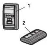
Accessories
| Description | Part Number | |
| 1 | Motion Detecting Control Panel | 041A7327-1 |
| 2 | 3-Button Remote Control | 953ESTD |
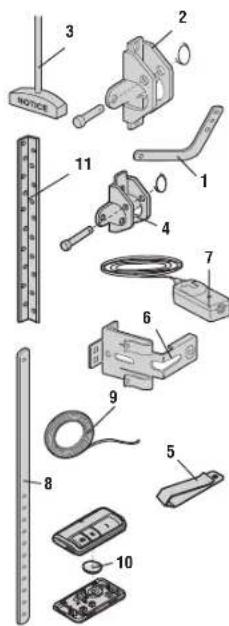
Installation Parts
| Description Part Number | ||
| 1 Curved Door Arm 178B35 | ||
| 2 Door Bracket with Clevis Pin and Fastener | 41A5047-1 | |
| 3 Emergency Release Rope and Handle | 41A2828 | |
| 4 Header Bracket with Clevis Pin and Fastener | 41A5047-2 | |
| 5 Remote Control Visor Clip | 29B137 | |
| 6 Safety Sensor Bracket 041A5266-3 | ||
| 7 Safety Sensor Kit Receiving and sending sensors with 2-conductor wire | 41A5034 | |
| 8 Straight Door Arm 178B34 | ||
| 9 White and Red/White Wire | 41B4494-1 | |
| 10 3V CR2032 Lithium Battery | 10A20 | |
| 11 Hanging Brackets | 12B776 | |
| Not Shown | ||
| Owner's Manual | 114A5063 | |
Repair Parts
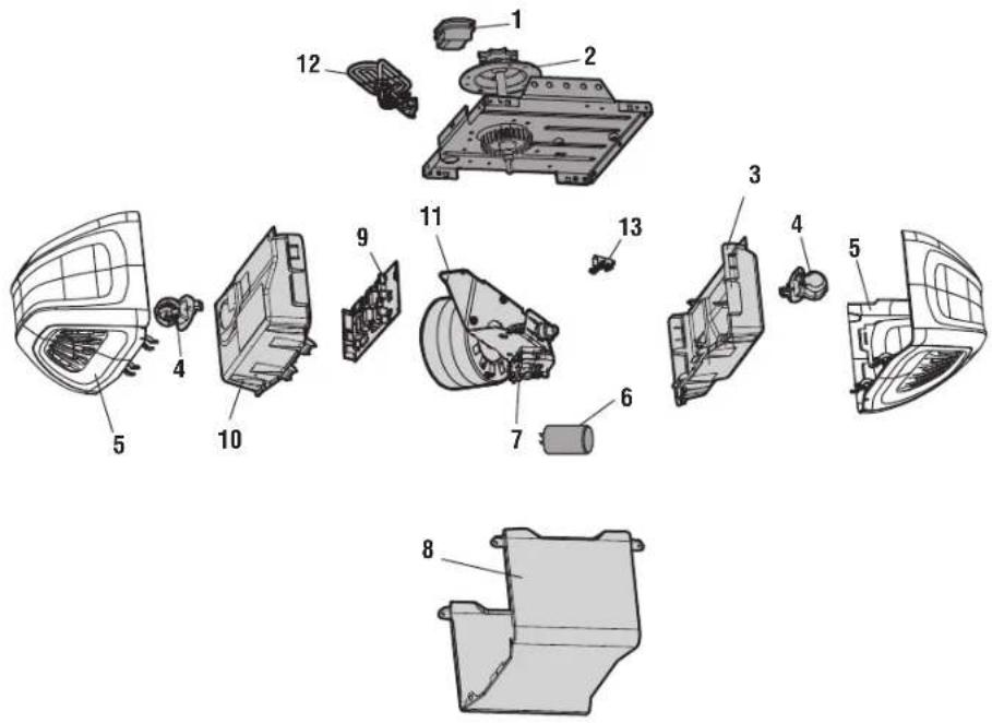
Garage Door Opener Parts
© 2017, The Chamberlain Group, Inc.
114A5063 All Rights Reserved
| Description Part Number | |
| 1 Chain Spreader 041A5615 | |
| 2 Gear and Sprocket 041A5585 | |
| 3 End Panel with Light Socket 041A7760 | |
| 4 Light Socket 041C0279 | |
| 5 Light Lens 041D7572 | |
| 6 Capacitor 30B652 | |
| 7 Travel Module 041D7742-5 | |
| 8 Cover 041D8807 | |
| 9 Receiver Logic Board 045ACT | |
| 10 End Panel for Receiver Logic Board with Light Socket | 041D7638 |
| 11 Motor with Travel Module 041A7766 | |
| 12 Line Cord 041B4245-1 | |
| 13 Terminal Block 041A3150 | |
| Not Shown | |
| Wire Harness | 041D8921 |
The Chamberlain Group, Inc.
300 Windsor Drive
Oak Brook, IL 60523
OPTION A INSTALLATION AU MUR
OPTION C POSE AU SOL
Portes rigides unquipment
© 2017, The Chamberlain Group, Inc.
The Chamberlain Group, Inc.
300 Windsor Drive
Oak Brook, IL 60523