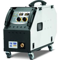
Easymig 1804XL - Welding machine GYS - Free user manual and instructions
Find the device manual for free Easymig 1804XL GYS in PDF.


User questions about Easymig 1804XL GYS
0 question about this device. Answer the ones you know or ask your own.
Ask a new question about this device
Download the instructions for your Welding machine in PDF format for free! Find your manual Easymig 1804XL - GYS and take your electronic device back in hand. On this page are published all the documents necessary for the use of your device. Easymig 1804XL by GYS.
USER MANUAL Easymig 1804XL GYS
natural_image
Line drawing of a portable electronic device with control panel, buttons, and wiring (no text or symbols)FR 2-11 / 94-112
EN 12-21 / 94-112
DE 22-31 / 94-112
ES 32-41 / 94-112
RU 42-52 / 94-112
NL 53-62 / 94-112
IT 63-72 / 94-112
PL 73-83 / 94-112
cz 84-93 / 94-112
Easymig 160 Easymig 160 XL Easymig 180-4XL
Poste à souder MIG
MIG/MAG Welding
natural_image
Silhouette of a person with a large number 6 and a small object nearby, no text or symbols presenttext_image
Warning symbol and warning icon with house, speaker, and warning symbolnatural_image
Silhouette of a person with motion lines and a small object, no text or symbols presentINSTALLATION – FONCTIONNEMENT PRODUIT
DESCRIPTION
ANOMALIES, CAUSES, REMEDES
Read and understand the following safety recommendations before using or servicing the unit.
Any change or servicing that is not specified in the instruction manual must not be undertaken.
The manufacturer is not liable for any injury or damage caused due to non-compliance with the instructions featured in this manual.
In the event of problems or uncertainties, please consult a qualified person to handle the installation properly.
ENVIRONMENT
This equipment must only be used for welding operations in accordance with the limits indicated on the descriptive panel and/or in the user manual. The operator must respect the safety precautions that apply to this type of welding. In case of inedaquate or unsafe use, the manufacturer cannot be held liable for damage or injury.
This equipment must be used and stored in a place protected from dust, acid or any other corrosive agent.
Operate the machine in an open, or well-ventilated area.
Operating temperature:
Use between -10 and +40°C (+14 and +104°F).
Store between -20 and +55°C (-4 and 131°F).
Air humidity:
Lower or equal to 50% at 40°C (104°F).
Lower or equal to 90% at 20°C (68°F).
Altitude: Up to 1000 meters above sea level (3280 feet).
INDIVIDUAL PROTECTIONS AND OTHERS
Arc welding can be dangerous and can cause serious and even fatal injuries.
Welding exposes the user to dangerous heat, arc rays, electromagnetic fields, noise, gas fumes, and electrical shocks. People wearing pacemakers are advised to consult with their doctor before using this device.
To protect oneself as well as the other, ensure the following safety precautions are taken:

In order to protect you from burns and radiations, wear clothing without cuffs. These clothes must be insulated, dry, fireproof and in good condition, and cover the whole body.

Wear protective gloves which guarantee electrical and thermal insulation.

Use sufficient welding protective gear for the whole body: hood, gloves, jacket, trousers... (varies depending on the application/operation). Protect the eyes during cleaning operations. Do not operate whilst wearing contact lenses.
It may be necessary to install fireproof welding curtains to protect the area against arc rays, weld spatters and sparks.
Inform the people around the working area to never look at the arc nor the molten metal, and to wear protective clothes.

Ensure ear protection is worn by the operator if the work exceeds the authorised noise limit (the same applies to any person in the welding area).
Stay away from moving parts (e.g. engine, fan...) with hands, hair, clothes etc...
Never remove the safety covers from the cooling unit when the machine is plugged in - The manufacturer is not responsible for any accident or injury that happens as a result of not following these safety precautions.
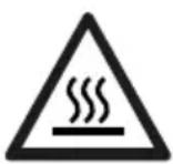
The pieces that have just been welded are hot and may cause burns when manipulated. During maintenance work on the torch or the electrode holder, you should make sure it's cold enough and wait at least 10 minutes before any intervention. The cooling unit must be on when using a water cooled torch in order to ensure that the liquid does not cause any burns. ALWAYS ensure the working area is left as safe and secure as possible to prevent damage or accidents.
WELDING FUMES AND GAS
natural_image
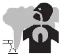
Silhouette of a person with a question mark inside, standing beside a smokestack (no text or symbols)The fumes, gases and dust produced during welding are hazardous. It is mandatory to ensure adequate ventilation and/or extraction to keep fumes and gases away from the work area. An air fed helmet is recommended in cases of insufficient air supply in the workplace. Check that the air intake is in compliance with safety standards.
Care must be taken when welding in small areas, and the operator will need supervision from a safe distance. Welding certain pieces of metal containing lead, cadmium, zinc, mercury or beryllium can be extremely toxic. The user will also need to degrease the workpiece before welding.
Gas cylinders must be stored in an open or ventilated area. The cylinders must be in a vertical position secured to a support or trolley.
Do not weld in areas where grease or paint are stored.
FIRE AND EXPLOSIONS RISKS
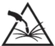
Protect the entire welding area. Compressed gas containers and other inflammable material must be moved to a minimum safe distance of 11 meters. A fire extinguisher must be readily available.
Be careful of spatter and sparks, even through cracks. It can be the source of a fire or an explosion.
Keep people, flammable objects and containers under pressure at a safe distance.
Welding of sealed containers or closed pipes should not be undertaken, and if opened, the operator must remove any inflammable or explosive materials (oil, petrol, gas...).
Grinding operations should not be directed towards the device itself, the power supply or any flammable materials.
GAS BOTTLE

Gas leaking from the cylinder can lead to suffocation if present in high concentrations around the work area.
Transport must be done safely: Cylinders closed and product off. Always keep cylinders in an upright position securely chained to a fixed support or trolley.
Close the bottle after any welding operation. Be wary of temperature changes or exposure to sunlight.
Cylinders should be located away from areas where they may be struck or subjected to physical damage.
Always keep gas bottles at a safe distance from arc welding or cutting operations, and any source of heat, sparks or flames.
Be careful when opening the valve on the gas bottle, it is necessary to remove the tip of the valve and make sure the gas meets your welding requirements.
ELECTRIC SAFETY
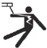
The machine must be connected to an earthed electrical supply. Use the recommended fuse size.
An electrical discharge can directly or indirectly cause serious or deadly accidents.
Do not touch any live part of the machine (inside or outside) when it is plugged in (Torches, earth cable, cables, electrodes) because they are connected to the welding circuit.
Before opening the device, it is imperative to disconnect it from the mains and wait 2 minutes, so that all the capacitors are discharged.
Do not touch the torch or electrode holder and earth clamp at the same time.
Damaged cables and torches must be changed by a qualified and skilled professional. Make sure that the cable cross section is adequate with the usage (extensions and welding cables). Always wear dry clothes in good condition, in order to be insulated from the electrical circuit. Wear insulating shoes, regardless of the environment in which you work in.
CEM CLASSIFIED MATERIAL

These Class A devices are not intended to be used on a residential site where the electric current is supplied by the public network, with a low voltage power supply. There may be potential difficulties in ensuring electromagnetic compatibility on these sites, because of the interferences, as well as radio frequencies.
This equipment does not comply with IEC 61000-3-12 and is intended to be connected to private low-voltage systems interfacing with the public supply only at the medium- or high-voltage level. On a public low-voltage power grid, it is the responsibility of the installer or user of the device to ensure, by checking with the operator of the distribution network, which device can be connected.
Provided that the impedance of the low-voltage public electrical network at the common coupling point is less than Zmax = 0.41 Ohms, this equipment complies with IEC 61000-3-11 and can be connected to public low-voltage electrical mains. It is the responsibility of the installer or user of the equipment to ensure, in consultation with the distribution network operator if necessary, that the network impedance complies with the impedance restrictions.
ELECTROMAGNETIC INTERFERENCES
natural_image
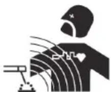
Silhouette of a person with motion lines and a small object, no text or symbols presentThe electric currents flowing through a conductor cause electrical and magnetic fields (EMF). The welding current generates an EMF field around the welding circuit and the welding equipment.
The EMF fields may disrupt some medical implants, such as pacemakers. Protection measures should be taken for people wearing medical implants. For example, access restrictions for passers-by or an individual risk evaluation for the welders.
All welders should take the following precautions in order to minimise exposure to the electromagnetic fields (EMF) generated by the welding circuit::
- position the welding cables together – if possible, attach them;
- keep your head and torso as far as possible from the welding circuit;
- never enroll the cables around your body;
-
never position your body between the welding cables. Hold both welding cables on the same side of your body;
-
connect the earth clamp as close as possible to the area being welded;
- do not work too close to, do not lean and do not sit on the welding machine
- do not weld when you're carrying the welding machine or its wire feeder.
People wearing pacemakers are advised to consult their doctor before using this device. Exposure to electromagnetic fields while welding may have other health effects which are not yet known.
RECOMMENDATIONS TO ASSESS THE WELDING AREA AND WELDING INSTALLATION
Overview
The user is responsible for installing and using the arc welding equipment in accordance with the manufacturer's instructions. If electromagnetic disturbances are detected, it is the responsibility of the user of the arc welding equipment to resolve the situation with the manufacturer's technical assistance. In some cases, this remedial action may be as simple as earthing the welding circuit. In other cases, it may be necessary to construct an electromagnetic shield around the welding power source and around the entire piece by fitting input filters. In all cases, electromagnetic interferences must be reduced until they are no longer bothersome.
Welding area assessment
Before installing the machine, the user must evaluate the possible electromagnetic problems that may arise in the area where the installation is planned.
. In particular, it should consider the following:
a) the presence of other power cables (power supply cables, telephone cables, command cable, etc...) above, below and on the sides of the arc welding machine.
b) television transmitters and receivers ;
c) computers and other hardware;
d) critical safety equipment such as industrial machine protections;
e) the health and safety of the people in the area such as people with pacemakers or hearing aids;
f) calibration and measuring equipment
g)The isolation of the equipment from other machinery.
The user will have to make sure that the devices and equipments that are in the same room are compatible with each other. This may require extra precautions;
h) make sure of the exact hour when the welding and/or other operations will take place.
The surface of the area to be considered around the device depends on the building's structure and other activities that take place there. The area taken in consideration can be larger than the limits determined by the companies.
Welding area assessment
Besides the welding area, the assessment of the arc welding systems intallation itself can be used to identify and resolve cases of disturbances. The assessment of emissions must include in situ measurements as specified in Article 10 of CISPR 11. In situ measurements can also be used to confirm the effectiveness of mitigation measures.
RECOMMENDATION ON METHODS OF ELECTROMAGNETIC EMISSIONS REDUCTION
a. National power grid: The arc welding machine must be connected to the national power grid in accordance with the manufacturer's recommendation. If interferences occur, it may be necessary to take additional preventive measures such as the filtering of the power supply network. Consideration should be given to shielding the power supply cable in a metal conduit. It is necessary to ensure the shielding's electrical continuity along the cable's entire length. The shielding should be connected to the welding current's source to ensure good electrical contact between the conduct and the casing of the welding current source.
b. Maintenance of the arc welding equipment: The arc welding machine should be submitted to a routine maintenance check according to the manufacturer's recommendations. All accesses, service doors and covers should be closed and properly locked when the arc welding equipment is on.. The arc welding equipment must not be modified in any way, except for the changes and settings outlined in the manufacturer's instructions. The spark gap of the arc start and arc stabilization devices must be adjusted and maintained according to the manufacturer's recommendations.
c. Welding cables: Cables must be as short as possible, close to each other and close to the ground, if not on the ground.
d. Electrical bonding : consideration should be given to bonding all metal objects in the surrounding area. However, metal objects connected to the workpiece increase the riskof electric shock if the operator touches both these metal elements and the electrode. It is necessary to insulate the operator from such metal objects.
e. Earthing of the welded part : When the part is not earthed - due to electrical safety reasons or because of its size and its location (which is the case with ship hulls or metallic building structures), the earthing of the part can, in some cases but not systematically, reduce emissions It is preferable to avoid the earthing of parts that could increase the risk of injury to the users or damage other electrical equipment. If necessary, it is appropriate that the earthing of the part is done directly, but in some countries that do not allow such a direct connection, it is appropriate that the connection is made with a capacitor selected according to national regulations.
f. Protection and plating : The selective protection and plating of other cables and devices in the area can reduce perturbation issues. The protection of the entire welding area can be considered for specific situations.
TRANSPORT AND TRANSIT OF THE WELDING MACHINE

The machine is fitted with handle(s) to facilitate transportation. Be careful not to underestimate the machine's weight. The handle(s) cannot be used for slinging.
Do not use the cables or torch to move the machine. The welding equipment must be moved in an upright position.
Do not place/carry the unit over people or objects.
Never lift the machine while there is a gas cylinder on the support shelf. A clear path is available when moving the item. The removal of the wire reel from the machine is recommended before undertaking any lifting operation.

Stray welding currents/voltages may destroy earth conductors, damage electrical equipment or cause components to warm up which may cause a fire.
- All welding connections must be firmly secured, check regularly!
- Check that the metal piece fixation is strong and without any electrical problems!
- Attach or hang all the electrically conductive elements, such as the trolley and slinging equipment, in order to insulate them
- Do not place any electrical equipment, such as drills or grinders, on top of the welding machine without insulating them!
- Always place welding torches or electrodes holders on an insulated surface when they're not in use!
EQUIPMENT INSTALLATION
- Put the machine on the floor (maximum incline of 10^ ).
- Ensure the work area has sufficient ventilation for welding, and that there is easy access to the control panel.
- The machine must not be used in an area with conductive metal dusts.
- The machine must be placed in a sheltered area away from rain or direct sunlight.
- The machine protection level is IP21, which means :
- Protection against access to dangerous parts from solid bodies of a ≥12.5mm diameter and,
- Protection against vertically falling drops.
The power cables, extensions and welding cables must be fully uncoiled to prevent overheating.

The manufacturer does not incur any responsibility regarding damages to both objects and persons that result from an incorrect and/or dangerous use of the machine.
MAINTENANCE / RECOMMENDATIONS
- Maintenance should only be carried out by a qualified person. Annual maintenance is recommended.
- Ensure the machine is unplugged from the mains, and wait for two minutes before carrying out maintenance work. DANGER High Voltage and Currents inside the machine.
- Remove the casing 2 or 3 times a year to remove any excess dust. Take this opportunity to have the electrical connections checked by a qualified person, with an insulated tool.
- Regularly check the condition of the power supply cable. If the power cable is damaged, it must be replaced by the manufacturer, its after sales service or an equally qualified person.
- Ensure the ventilation holes of the device are not blocked to allow adequate air circulation.
- Do not use this equipment to thaw pipes, to charge batteries, or to start any engine.
INSTALLATION – PRODUCT OPERATION
DESCRIPTION
Thank you for choosing this machine. To get the best use from your machine, please read the following carefully: The Easymig range are semi-automatic MIG/MAG, MMA and flux cored wire welding stations. They are manual settings machine, with the help of the table printed on the product. They are recommended for welding steel, stainless steel and aluminium.
ELECTRICITY SUPPLY
This machine is fitted with a 16A socket type CEE7/7 which must be connected to a single-phase 230V (50 - 60 Hz) power supply fitted with three wires and one earthed neutral. The absorbed effective current (I1eff) is displayed on the machine, for optimal use. Check that the power supply and its protection (fuse and/or circuit breaker) are compatible with the current needed by the machine. In some countries, it may be necessary to change the plug to allow the use at maximum settings. The device must be installed so that the mains socket is accessible.
Do not use an extension cable with a diameter of less than 1.5mm^2 . Easymig is delivered with a 16amp plug (TYPE CEE7-7).
This machine must be connected to an EARTHED power supply 230V, 50/60 Hz, and protected by a 16A circuit breaker.
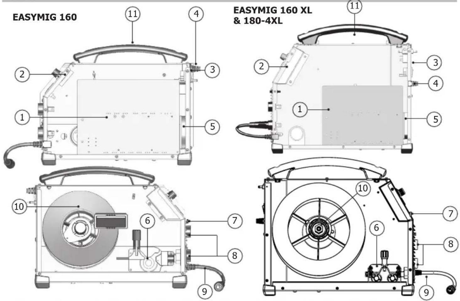
MACHINE DESCRIPTION (FIG I / P.76)
1 : Adjustment of welding settings (wire speed, welding voltage and inductance).
2 : Switch MIG/ MMA
3 : European standard torch connection.
4 : Connectors
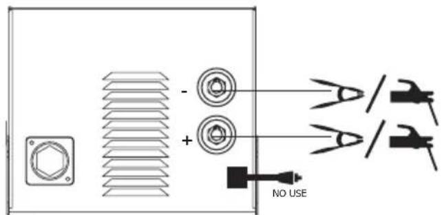
5 : Polarity reversal cable
6 : Power Cable (2 m)
7 : Power switch
8 : Reel adaptor 100/200mm (EASYMIG 160)
Reel adaptor 200/300mm (EASYMIG 160 XL)
9 : Digital displays
SEMI-AUTOMATIC WELDING FOR STEEL / STAINLESS STEEL (MAG MODE)
Set the voltage output and the wire speed according to the thickness of the weld piece, following the instructions/recommendations printed on the side of the machine.
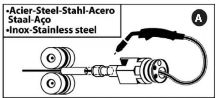
The Easymig can weld Steel wire 0.6/0.8mm, and Stainless Steel of 0.8mm.
The machine is fitted with ∅ 0.8mm Steel or Stainless Steel rollers. The contact tube, the groove of the roller and the sleeve of the torch are all compatible with 0.8mm wire. Should you wish to weld 0,6 wire, use a torch
of maximum 3m long. The contact tip must be changed (fig II A / p.76) as well as the wire feeder's roller that must be replaced by an optional reference (042339) with a 0.6 diameter groove. In this case, the position in such a way to observe 0.6. For use with Steel, the gas requirement is argon + CO2. (Ar+CO2). The proportion of CO2 required will vary depending on the use. For Stainless Steel, use the combination of 2% CO2 For specific gas requirements, please contact your gas distributor. The gas flow in steel is between 8 and 12 Litres/minute depending on the environment.
SEMI-AUTOMATIC WELDING FOR ALUMINIUM (MIG MODE)
Set the voltage output and the wire speed according to the thickness of the weld piece, following the instructions/recommendations printed on the side of the machine.
The Easymig can be equipped to weld with aluminium wire ∅ 0,8 or 1,0 (fig II-B / p.76).
For use with aluminium, the gas requirement is pure argon (Ar). For the specific gas requirements please contact your distributor. The gas flow in Aluminium is between 20 and 30 Litres/minute depending on the environment, and the experience of the welder.
Below are the differences between welding with Steel and Aluminium :
- Specific rollers are needed for welding with Aluminium.
- Adjust the pressure of the drive rolls to prevent the wire being crushed.
- Only use a capillary tube for welding with Steel or Stainless Steel.
- Use a special Aluminium Torch with a teflon sheath to reduce friction.
DO NOT cut the sheath close to the joint, it is used to guide the wire from the the rollers.
- Contact Tube : Use a special aluminium contact tube specific to the diameter of wire being used.
GASLESS WIRE WELDING
Set the voltage output and the wire speed according to the thickness of the weld piece, following the instructions/recommendations printed on the side of the machine.
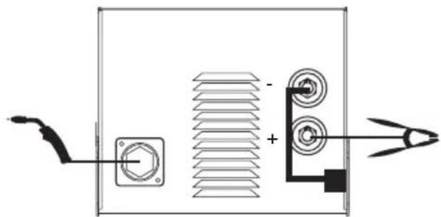
The Easymig can weld gasless wire up to 0.9mm, if the polarity is reversed (fig III / p.77) respecting a maximum pressure of 5Nm. For parameters of use, please refer to the instructions indicated on page 76. Welding gasless wire with a standard nozzle can lead to overheating and deterioration of the torch. It is recommended to use a "No Gas" nozzle (ref. 041868), or remove the genuine nozzle (Fig. III / p.77).
ELECTRODE WELDING
- The reverse polarity cable must be disconnected in MMA (stick welding) mode in order to connect the electrode holder and earth clamp. Connect the electrode holder and earth clamp as indicated on the electrode packaging.
- Respect the basic rules of welding.
- This device has 1 feature specific to Inverter machines :
- Anti-Sticking: Enables easy removal of the electrode from the metal. The anti-sticking feature, after its start, requires approximately a 3 seconds delay before resuming normal welding operations.
The proportion of CO2 can vary according to the type of metal being welded.
SETTINGS PANEL (FIG V/P.77)
 | · Green light «ON»: when the machine is switched on the light turns on.· In case of power failure, the green light goes off but the device remains powered while the power cable is unplugged. |  |
 3 3 | · Orange light :· Over-temperature: in such a case you shall wait a few minutes, the light will turn off and the machine will start again.· Over-current on primary circuit: in such a case you shall switch off the machine (with the main switch) and switch on.- MIG / MAG Welding : Adjust the wire feeder speed up to maximum speed.Wire speed selection from 3 to 10 m/min.- MMA welding : Adjust the welding current. | 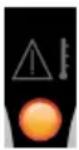 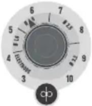 |
| 4 | •Adjust the voltage reference up to the maximum value. | 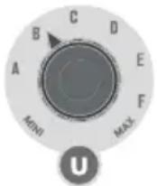 |
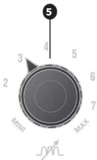
| 5 | Welding arc dynamic potentiometer : Can manually adjust the arc dynamic.MINI to MAX settings : Hard arc to soft arc. | 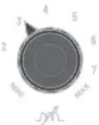 |
| MIG/MAG recommendationsThe wire speed adjustment is often determined « with the assistance of sound »: the arc must be stable and have a low crackling.If the speed is too low, the arc is not continuous.If the speed is too high, the arc crackles and the wire pushes back the torch.The inductance adjustment is done according to the welder's preferences :The lower the inductance, the more the arc will be hard and guiding.The higher the inductance and the softer the arc with little splatter. | ||
PROCESS OF REELS AND TORCHES ASSEMBLY (FIG IV / P.77):
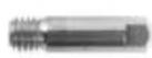
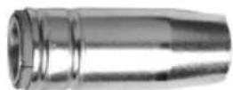
- Remove the contact tube and its support (fig D), and the nozzle (fig E) from the torch.
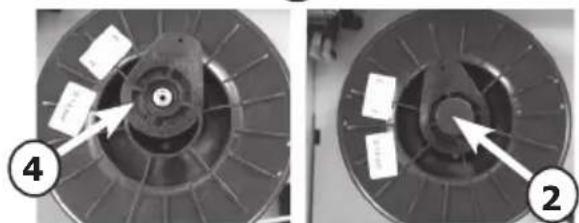
Fig A : • Position the wire reel on the reel support :
- Adjust the reel brake (1) to avoid reel movement tangling the wire when welding stops. Be careful not to tighten too much.
- For a 200mm wire reel tighten the reel to the maximum. The adaptor (4) is only to be used for a 200mm reel.
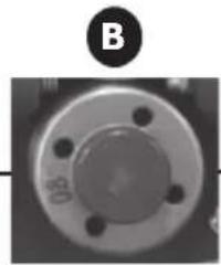
Fig B : The drive rollers included have 2 grooves (0,8 and 0,9). For 0.8mm steel wire, use the V shaped groove. For flux cored wire, remove and reverse the roller to use the 0.9mm groove.
For 0.8mm aluminium wire, remove and replace the roll with a model specifically designed for aluminium with a U shaped groove (not included).
Fig C : To select the adjustment of the drive rollers.
- Loosen the drive roller knob (3) as far as possible and insert the wire, tighten the knob again slightly.
- Start the motor by pressing the trigger of the torch.
- Tighten the knob whilst pressing the trigger until the wire starts to move.
Nb : When welding with Aluminium, use the minimum possible pressure to avoid crushing the wire
- Leave about 5cm of wire out of the torch, then put the contact tube (fig. D), and the nozzle (fig. E) adapted to the wire to be used at the extremity.
GAS COUPLING
- Connect a pressure regulator to the gas bottle. Connect the welding machine using the pipes supplied, and place the two clamps to avoid leakages.
- Set the gas flow by adjusting the dial located on the pressure regulator.
NB : to help facilitate the adjustment of the gas flow, operate the drive rollers by pressing the trigger of the torch (ensure that the drive roller is completely loose so the wire is not fed through).
Maximum gas pressure 0.5MPA (5 bars).
This procedure does not apply to «Gasless» welding mode.
RISK OF INJURY DUE TO MOVING PARTS
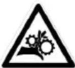
The wire feeders contain moving parts that may catch hand, hair, clothes or tools which can lead to injuries! Take extra care.
- Do not lay a hand to swivel or moving components or parts to the drive!
- Ensure that the housing covers or protective covers remain closed during operation!
ADVICE & THERMAL PROTECTION
This device is equipped with a ventilator regulated by the inside temperature. When the machine's thermal protection is activated, it will not deliver any current. Orange light (Fig-V-2 / p.77) will turn on until the temperature of the machine has returned to normal.
- Do not block/cover the ventilation holes, ensure free flow of air.
- Whilst in thermal protection mode leave the machine plugged into the mains after welding to allow it to cool. General observations :
• Always respect the basic rules of welding.
• Always work in an adequately ventilated area. - Do not work on a damp surface.
TROUBLESHOOTING
| SYMPTOMS POSSIBLE CAUSES REMEDIES | ||
| The welding wire speed is not constant. | Debris is blocking up the opening. Clean | out the contact batch or change it and replace the anti-adherence product. Ref.041806. |
| The wire skids in the rollers. • Control the roller pressure or replace it. • Wire diameter non-compatible with roller • Covering wire guide in the torch non-compatible." | ||
| The wire-feeder motor doesn't operate. | Reel or roller brake too tight. Release the brake and rollers. | |
| Electrical supply problem. Check that the power switch is in the "On" position. | ||
| Bad wire feeding. Covering | wire guide dirty or damaged. Clean or replace | |
| The drive roller is too loose Tighten the drive roller knob | ||
| Reel brake too tight Release the brake | ||
| No welding current Bad connection to the main supply. Check the mains connection and look if the plug is fed by 230 V (1PH) power socket. | ||
| The welding bead is porous | The gas flow rate is not sufficient. Adjust flow range 15 to 20 L / min. | |
| Gas bottle empty. Replace it. | ||
| Gas quality unsatisfactory. Replace it. | ||
| Air flow or wind influence. Prevent drafts, protect welding area. | ||
| Gas nozzle dirty. Clean or replace the gas nozzle. | ||
| Poor quality wire. Use suitable WIRE for MIG-MAG welding. | ||
| Surface to weld in bad condition. (rust, etc...) | Clean the metal before welding. | |
| Very important flashing particules. | Arc voltage too low or too high. See welding settings. | |
| Bad earth connection. Adjust the earth cable for a better connection. | ||
| Insufficient gas flow. Adjust the gas flow. | ||
| No gas flow at the end of the torch. | Bad gas connection. Check the gas connection at the welding machine. Check the gas regulator and the solenoid valves. | |
natural_image
Silhouette of a person with a large number 6 and a downward arrow, symbolizing decline or reduction (no text or symbols present)natural_image
Silhouette of a person wearing a helmet and holding a device, with no visible text or symbolsnatural_image
Silhouette of a person with a question mark inside, emitting smoke from a cloud-like shape (no text or symbols)natural_image
Silhouette of a person wearing a helmet and holding a device, with motion lines indicating movement (no text or symbols)natural_image
Silhouette of a person with a smokestack emitting vapor, next to a small lamp (no text or symbols)WAARSCHUWING - VEILIGHEIDSINSTRUCTIES
ALGEMENE INSTRUCTIES

natural_image
Silhouette of a person with a smokestack emitting vapor, no text or symbols presenttext_image
Warning symbols including a house, a switch, and an orange warning symbol with an exclamation marknatural_image
Silhouette of a person with motion lines and abstract patterns, possibly depicting a dynamic scene or signal (no text or symbols)INSTALLATIE VAN HET APPARAAT
natural_image
Silhouette of a person with a downward arrow and a small object, no text or symbols presentnatural_image
Silhouette of a person wearing a helmet and holding a tool, with motion lines indicating movement (no text or symbols)natural_image
Silhouette of a person with a smokestack emitting vapor, no text or symbols presenttext_image
Warning symbol and warning icon with house, speaker, and warning symbolnatural_image
Silhouette of a person with heart-shaped symbols inside, possibly indicating cardiac or medical imaging (no text or labels)natural_image
Silhouette of a person with a downward arrow and a small object, no text or symbols presenttext_image
Warning symbol and warning icon with Chinese text, including a house outline, speaker, and electrical hazard symbolnatural_image
Silhouette of a person with motion lines and abstract shapes, possibly depicting a dynamic or mechanical process (no text or symbols)CONDITIONS DE GARANTIE
The warranty covers faulty workmanship for 2 years from the date of purchase (parts and labour).
The warranty does not cover:
- Transit damage.
- Normal wear of parts (eg. : cables, clamps, etc..).
- Damages due to misuse (power supply error, dropping of equipment, disassembling).
- Environment related failures (pollution, rust, dust).
In case of failure, return the unit to your distributor together with:
- The proof of purchase (receipt etc ...)
- A description of the fault reported
GARANTIE
text_image
Labeled diagram of a device front panel with numbered components for identification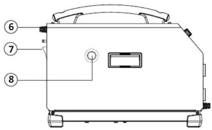
text_image
⑥ ⑦ ⑧II
text_image
•Acier-Steel-Stahl-Acero Staal-Aço •Inox-Stainless steel A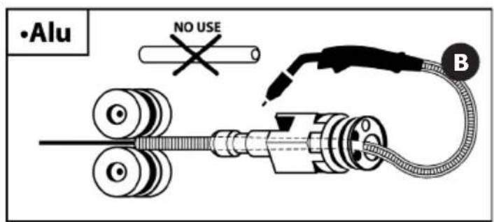
text_image
•Alu NO USE BMIG-MAG
natural_image
Pure electrical circuit lines without any symbols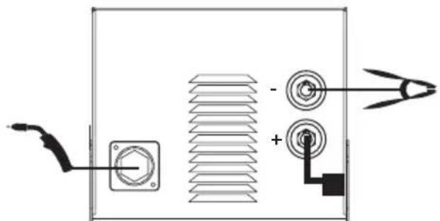
natural_image
Pure electrical circuit lines without any symbolsGASNO GAS
MMA
FR - Vérifier la polarité de l'électrode sur l'emballage.
EN - Check the electrode polarity on the packaging.
DE - Beachten Sie die auf der Elektrodenverpackung beschriebenen Angaben zur Polarität.
ES – Compruebe la polaridad del electrodo sobre el embalaje.
RU – Проверить полярность электрода на упаковке.
NL - Controleer de polariteit van de elektrode aangegeven op de verpakking.
IT - Verificare la polarità dell'elettrodo sulla confezione.
PL - Sprawdzić polaryzację elektrody na opakowaniu.
CZ - Zkontrolujte polaritu elektrody uvedena na obalu.
text_image
- + NO USEnatural_image
Two mechanical components: a cylindrical connector with a metallic end and a circular knob with an arrow pointing to it, labeled ① and ② (no text or symbols on the parts themselves)A
natural_image
Two circular mechanical components with labeled parts, shown from different angles (no text or symbols present)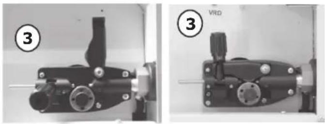
natural_image
Two views of a mechanical device with labeled parts, showing front and side views (no readable text or symbols)C
natural_image
Close-up of a mechanical component with a circular flange and four bolt holes, labeled 'B' (no readable text or symbols beyond label)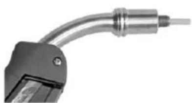
natural_image
Close-up of a metallic tool with a curved handle and shaft (no visible text or symbols)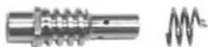
D
E
V
text_image
5 4 3 2 MINI MAX 5 6 7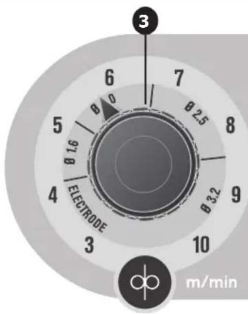
text_image
6 7 8 9 10 m/min 3 0 0 0.25 0.32 0.16 0 5 4 ELECTRODE 3 dp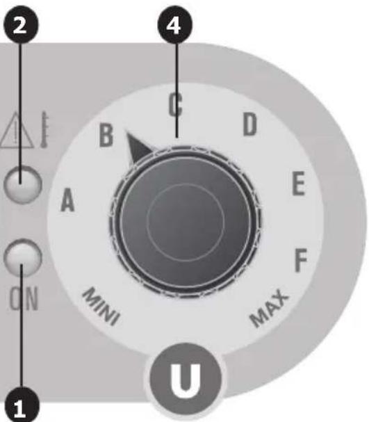
text_image
2 4 C B D A E MINI F MAX U ON 1PIÈCES DE RECHANGE / SPARE PARTS / ERSATZTEILE / PIEZAS DE REPUESTO / ЗАПАСНЫЕ ЧАСТИ / RESERVE ONDERDELEN / PEZZI DI RICAMBIO / CZĘŚCI ZAMIENNE / NAHRÁDNÍ DÍLY
| N° | 160 | 160 XL | 180 -4 XL | |
| 1 | Carte principale / Main circuit board / Hauptplatine / Tarjeta principal / Основная плата / Hoofd printplaat / Carta principale / Płyta główna / Hlavní deska | 53497 B4111 | ||
| 2 | Carte affichage / Display card / Anzeigeplatine /Placa frontal (display) / Плата отображения на дисплее / Display plaat / Scheda display / Karta graficzna / Deska indikací | 53498 | ||
| 3 | Interrupteur /Switch / An/ Aus- Schalter /Interruptor / Переключатель / Schakelaar / Interruttore / Wyłącznik / Spínač zap./vyp. | 53546 | ||
| 4 | Câble d'alimentation / Power lead / Netzstromkabel / Cable de alimentación / Шнур питания / Voedingskabel / Cavo di rifornimento / Kabel zasilania / Napájecí kabel | 21468 | ||
| 5 | Ventilateur / Fan /Ventilator/Ventilador / Вентилятор / Ventilator / Ventilatore / Wentylator / Ventilátor | 51048 | C16550 | |
| 6 | Motodévidoir (sans galet) / Wire feeder (without roller) / Drahtvorschubantrieb (ohne Drahtrollen) / Devanadera (sin rodillos) / Подающий механизм (без ролика) / Spoeldraadhaspel (zonder rol) / Trainafilo (senza rullo) / Podajnik drutu (bez rolki) / Podavač drátu (bez kladky) | 51026 | 53530 Q | 51566 |
| 7 | Interrupteur MIG/MMA /Switch MIG/MMA/ An/ Aus- Schalter MIG/MMA /Interruptor MIG/MMA/ Переключатель MIG/MMA / Schakelaar MIG/MMA / interruttore MIG/MMA / Przełącznik MIG/MMA / Spínač výběru režimu MIG/ MMA | 52466 | ||
| 8 | Connecteur 1/4 cable de masse / Earth cable connector (1/4) / (+) und (-) Anschlussbuchsen / Conector cable de masa (1/4) / Коннектор (1/4) кабеля массы / 1/4 massa kabel aansluiting / Connettore 1/4 cavo di massa / Złącze 1/4 kabla uziemienia / Připojka kabelu ukostření | 51469 | ||
| 9 | Câble d'inversion de polarité / Polarity reversal cable / Polaritätswahlstecker / Cable de inversión de polaridad / Кабель инверсии полярности / Polariteit inversie kabel / Cavo d'inversione di polarità / Kabel odwracający biegunowość / Kabel přepolování | 71918 | ||
| 10 | Support bobine / Reel stand / Rollenhalter / Soporte de bobina / Подставка для катушки / Spoel houder / Supporto bobina / Wspornik szpuli / Držák role | 71601 | 71608 + 56056 | |
| 11 | Poignée / handle / Griff / Asa / Рукоятка / Hendel / Impugnatura / Uchwyt / Rukojet' | 56048 | 56014 | |
SCHÉMA ÉLECTRIQUE / CIRCUIT DIAGRAM /SCHALTPLAN/ DIAGRAMA ELECTRICO
/ЭЛЕКТРИЧЕСКАЯ СХЕМА / ELEKTRISCHE SCHEMA / SCEMA ELETTRICO / SCHEMAT ELEKTRY-CZNY / ELEKTRICKÁ SCHÉMA
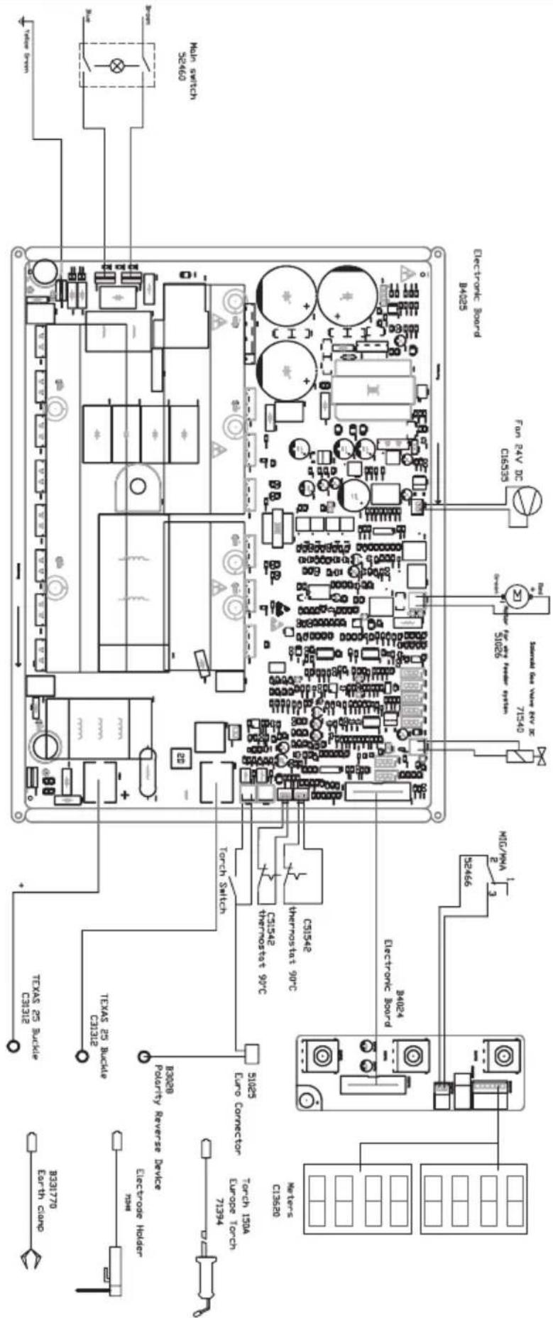
EASYMIG 160
text_image
Electric Board H4025 Electronic Board H4025 Main switch SE460 Power 316535 Fan 24V DC 71540 71026 71540 Motor C13520 Torch 150A Euro Connector 7394 Electrode Holder B0208 Torch Switch CS1542 Thermostat 90°C CS1542 Thermostat 90°C Texas 25 Bucide CAC12 Texas 25 Bucide CAC12 B33170 Earth clampEASYMIG 160 XL
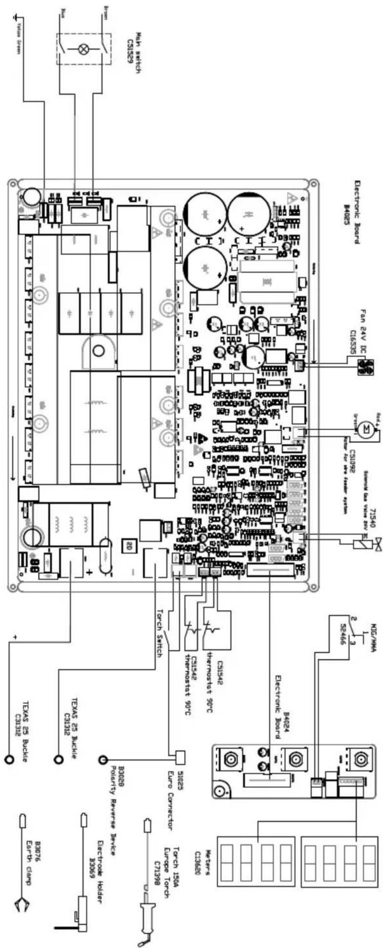
text_image
Electric Board M025 Electronic Board M025 Fan 24V DC C16535 CS1092 71540 SMMW 6A VOUT 24V 2 MIC/MA 5E-466 8024 Electronic Board B4024 3 M1G/MA 51025 Euro Connector Torch Switch TSX 25 Bucile C3132 TX 25 Bucile C3132 Texas 25 Bucile C3132 B3076 Earth Clamp Electrode Holder 33069 Electrode Holder CT1998 Torch 150A Europe Torch CT1998 Mears CD360EASYMIG 180 4-XL
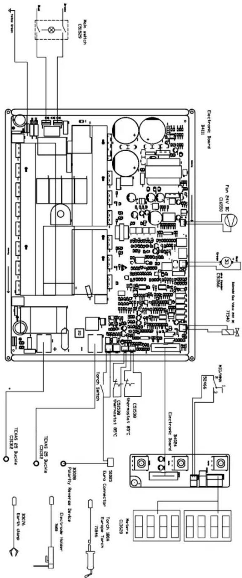
text_image
30076 Earth clamp Texas 25 Aucile C8132 Texas 25 Aucile C8132 3008 POUPITY REVERSE DEVICE Electrode Holder 7486 Torch 180A Euro Connector 7146 31025 Motor's C13620 Electronic Board 34024 52466 MIG/ANA 2 3 71540 SLS566 71540 SLS566 Fan 24V DC C16590 Electronic Board P4111Wiring Diogram EASYMIG 180-4XL
ICÔNES / SYMBOLS / ZEICHENERKLÄRUNG / SÍMBOLOS / CUMBOLЫ / PICTOGRAMMEN / ICONA / IKONY / VYSVĚTLENÍ SYMBOLŮ
| A Ampères - Ampes - Ampere - Amperios - Amnep - Ampère - Amper - Ampery - Ampér | |
| V Volt - Volt - Volt - Volt - Volt - Volt - Volt | |
| Hz Hertz - Hertz - Hertz - Hertz - Hertz - Hertz - Hertz - Hertz | |
 | - Soudage MIG/MAG (MIG: Metal Inert Gas / MAG: Metal Active Gas)- MIG/MAG Welding (MIG: Metal Inert Gas / MAG: Metal Active Gas)- MIG/MAG Schweißen (MIG: Metal Inert Gas/ MAG: Metal Active Gas)- Soldadura MIG/MAG (MIG: Metal Inert Gas / MAG: Metal Active Gas)- Полувтоматическая сварка MIG/MAG (MIG: Metal Inert Gas / MAG: Metal Active Gas)- MIG/MAG lassen (MIG: Metal Inert Gas / MAG: Metal Active Gas)- Saldatura MIG/MAG (MIG: Metal Inert Gas / MAG: Metal Active Gas)- Spawanie MIG / MAG (MIG: Metal Inert Gas / MAG: Metal Active Gas)- Svařování metodou MIG/MAG (MIG: Metal Inert Gas / MAG: Metal Active Gas) |
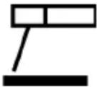 | - Soudage à l'électrode enrobée (MMA – Manual Metal Arc)- Electrode welding (MMA – Manual Metal Arc)- Schweißen mit umhüllter Elektrode (E-Handschweißen)- Soldadura con electrodos revestidos (MMA - Manual Metal Arc)- Ручная дуговая сварка (MMA)- Booglassen met beklede elektrode (MMA – Manual Metal Arc)- Saldatura all'elettrodo rivestito (MMA – Manual Metal Arc)- Spawanie elektrodami otulonymi (MMA - Manual Metal Arc)- Svařování obalenou elektrodou (MMA - Manual Metal Arc) |
 | - Convient au soudage dans un environnement avec risque accru de choc électrique. La source de courant elle-même ne doit toutefois pas être placée dans de tels locaux.- Adapted for welding in environment with increased risks of electrical shock. However, the welding source must not be placed in such places.- Geeignet für Schweißarbeiten im Bereich mit erhöhten elektrischen Risiken. Trotzdem sollte die Schweißquelle nicht unbedingt in solchen Bereichen betrieben werden.- Adaptado a la soldadura en un entorno que comprende riesgos de choque eléctrico. La fuente de corriente ella misma no debe estar situada dentro de tal locales.- Адаптирован для сварки в среде с повышенным риском электрошока. Однако сам источник питания не должен быть расположен в таких местах.- Geschikt voor het lassen in een ruimte met verhoogd risico op elektrische schok. De voedingsbron zelf moet echter niet in dergelijke ruimte worden geplaatst.- Conviene alla saldatura in un ambiente a grande rischio di scosse elettriche. L'origine della corrente non deve essere localizzata in tale posto.- Nadaje się do spawania w środowisku o zwiększonym ryzyku porażenia prądem. Samo źródło prądu nie może jednak być umieszczone w tego typu pomieszczeniach- Vhodné pro svářečské práce v oblasti se zvýšenými elektrickými riziky. Nicméně by zdroj nemusel být nutně provozován v těchto oblastech. |
| IP21 | - Le matériel est de degré de protection IP21, signifiant :une protection contre l'accès aux parties dangereuses des corps solides de diam >12.5mm et une protection contre les chutes verticales de gouttes d'eau.- The material is IP21 degree of protection, meaning:Protection against access to dangerous parts of solid bodies of diam> 12.5mm and protection against vertical drops of water drops.- Das Material hat Schutzart IP21, das heißt:Schutz gegen den Zugang zu gefährlichen Teile Festkörper mit einem Durchmesser von> 12,5 mm und Schutz gegen senkrecht fallende Wassertropfen.- El material tiene un grado de protección IP21, es decir:la protección contra el acceso a partes peligrosas de cuerpos sólidos de diámetro> 12,5 mm y la protección contra la caída vertical de gotas de agua.- Материал имеет степень защиты IP21, а это означает:защитa от доступа к опасным частям твердых тел диаметром> 12,5 mm и защита от вертикально падающих капель воды.- Het materiaal heeft beschermingsgraad IP21, betekenis:bescherming tegen toegang tot gevaarlijke delen van vaste stoffen met een diameter van> 12,5 mm en bescherming tegen verticaal vallende waterdruppels.- Il materiale ha grado di protezione IP21, significato:la protezione contro l'accesso a parti pericolose di corpi solidi di diametro> 12,5 millimetri e la protezione contro la caduta verticale di gocce d'acqua.- Urządzenie należy ustawiać i eksploatować wyłącznie zgodnie z informacjami o stopniu ochrony IP21, to znaczy:ochrona przed dostępem do niebezpiecznych części ciał stałych o średnicy >12,5mm oraz ochrona przed pionowymi kroplami wody.- Zařízení má stupeň krytí IP21, což znamená, že :ochrana před přístupem k nebezpečným částem pevných těles o průměru > 12,5 mm a ochrana před svislýmikapkami vody.10 |
| - Courant de soudage continu.- Welding direct current.- Gleichschweißstrom.- La corriente de soldadura es continua. | - Сварка на постоянном токе.- DC lasstroom.- Corrente di saldatura continuo.- Stały prąd spawania.- Stejnosměrný svařecí proud | |
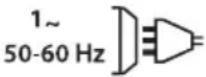 | - Alimentation électrique monophasée 50 ou 60Hz.- Single phase power supply 50 or 60Hz.- Einphasige Netzversorgung mit 50 oder 60Hz.- Alimentación eléctrica monofásica 50 o 60 Hz. | - Одnofазное напряжение 50 или 60Гц.- Enkel fase elektrische voeding 50Hz of 60Hz.- Alimentazione elettrica monofase 50 ou 60Hz.- Zasilanie jednofazowe 50 lub 60Hz- Jednofázové napájení 50 nebo 60 Hz. |
| U0 | - Tension assignée à vide.- Rated no-load voltage.- Leerlaufspannung.- Tensión asignada de vacío. | - Напряжение холостого хода.- Nullastspanning.- Tensione nominale a vuoto.- Znamionowe napięcie próżniowe.- Napětí naprázdno |
| U1 | - Tension assignée d'alimentation.- rated supply voltage.- Netzspannung.- Tensión de la red. | - Напряжение сети.- Netspanning.- Tensione nominale di alimentazione.- Napięcie znamionowe zasilania.- Napětí napájení |
| I1max | - Courant d'alimentation assigné maximal (valeur efficace).- Rated maximum supply current (effective value).- Maximaler Versorgungsstrom (Effektivwert).- Corriente máxima de alimentación de la red. | - Максимальный сетевой ток (эффективная мощность).- Aangewende maximale voedingstroom (effectieve waarde).- Corrente di alimentazione nominale massimo (valore efficace).- Maksymalny znamionowy prąd zasilania (wartość skuteczna).- Maximální jmenovitý napájecí proud (efektivní hodnota). |
| I1eff | - Courant d'alimentation effectif maximal.- Maximum effective supply current.- Maximaler tatsächlicher Versorgungsstrom.- Corriente de alimentación efectiva máxima.- Максимальный эффективный сетевой ток.- Maximale effectieve voedingstroom.- Corrente di alimentazione effettivo massimo.- Maksymalny skuteczny prąd zasilania.- Maximální skutečný napájecí proud. | |
| IEC 60974-1IEC 60974-5IEC 60974-10 | - L'apparell respecte les normes IEC 60974-1, IEC 60974-5, IEC 60974-10.- The device complies with IEC 60974-1, IEC 60974-5, IEC 60974-10 standard relative to welding units.- Das Gerät entspricht der Norm IEC 60974-1, IEC 60974-5, IEC 60974-10 für Schweißgeräte.- El aparato está conforme a las normas IEC 60974-1, IEC 60974-5, IEC 60974-10 referente a los aparatos de soldadura.- Annapat соответствует европейской норме IEC 60974-1, IEC 60974-5, IEC 60974-10.- Dit toestel voldoet aan de IEC 60974-1, IEC 60974-5, IEC 60974-10 norm.- Il dispositivo rispetta las normas IEC 60974-1, IEC 60974-5, IEC 60974-10.- Urządzenie to jest zgodne z normą EN60974-1, EN60974-5, EN60974-10.- Zařízení je v souladu s normami IEC 60974-1, IEC 60974-5, IEC 60974-10. | |
| [IMAGE] | - Source de courant de technologie onduleur délivrant un courant continu.- Inverter current technology based source delivering direct curent.- Invertergleichstromquelle.- Fuente de corriente de tecnología ondulador que libera corriente continua.- Источник тока с технологией преобразователя, выдающий постоянный ток.- Stroombron met UPS technologie, levert gelijkstroom.- Fonte di corrente con tecnologia inverter che rilascia una corrente continua.- Žródło prądu technologii falownika dostarczającego prąd stały.- Svařovací invertor generující jednosměrný proud. | |
| X(40°C) | - Facteur de marche selon la norme IEC 60974-1 (10 minutes – 40°C).- Duty cycle according to the standar IEC 60974-1 (10 minutes – 40°C).- Einschaltdauer gemäß IEC 60974-1 (10 Minuten – 40°C).- Factor de marcha según la norma IEC 60974-1 (10 minutos – 40°C).- ПВ% по норме IEC 60974-1 (10 минут – 40°C).- De vermogensfactor volgens de IEC 60974-1 norm (10 minuten - 40°C).- Ciclo di lavoro secondo la norma IEC 60974-1 (10 minuti – 40°C).- Cykl pracy zgodny z normą EN 60974-1 (10 minut - 40 °C).- Pracovní cyklus podle IEC 60974-1 (10 minut - 40 °C). | |
EASYMIG 160 / 160 XL / 180-4XL
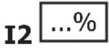 | - I2: courant de soudage conventionnel correspondant.- I2: corresponding conventional welding current.- I2: entsprechender Schweißstrom.- I2: Corrientes correspondientes. | - I2: Toki, соответствующие X*- I2 : overeenkomstige conventionele lasstroom.- I2: corrente di saldatura convenzionale corrispondente- Odpowiedni prąd spawania konwencjonalnego.- Odpovídající konvenční svařovací proud. |
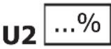 | - U2: Tensions conventionnelles en charges correspondantes.- U2: conventional voltages in corresponding load.- U2: entsprechende Arbeitsspannung.- U2: Tensiones convencionales en carga.- U2: соответствующие сварочные напряжения*- U2: conventionele spanning in corresponderende belasting.- U2: Tensioni convenzionali in cariche corrispondenti.- Napięcia konwencjonalne przy odpowiednich obciążeniach.- Konvenční napětí v odpovídajících zátěžích. | |
 | - Appareil conforme aux directives européennes. La déclaration de conformité est disponible sur notre site internet.- The device complies with European Directive. The certificate of compliance is available on our website.- Gerät entspricht europäischen Richtlinien. Die Konformitätserklärung finden Sie auf unsere Webseite.- El aparato está conforme a las normas europeas. La declaración de conformidad está disponible en nuestra página Web.- Устройство соответствует европейским нормам. Декларация соответствия есть на нашем сайте.- Het toestel is in overeenstemming met de Europese richtlijnen. De conformiteitsverklaring is te vinden op onze internetsite.- Dispositivo in conformità con le norme europee. La dichiarazione di conformità è disponibile sul nostro sito internet.- Urządzenie spełnia wymagania dyrektyw Unii Europejskiej. Deklaracja zgodności dostępna jest na naszej stronie internetowej.- Zařízení odpovídá evropským směrnicím. Prohlášení o shodě je dostupné na našich webových strankách | |
 | - Marque de conformité EAC (Communauté économique Eurasienne).- Conformity mark EAC (Eurasian Economic Commission).- EAC-Konformitätszeichen (Eurasische Wirtschaftsgemeinschaft).- Marca de conformidad EAC (Comunidad económica euroasiática).- Маркировка соответствия EAC (Евразийское экономическое сообщество).- EAC (Euraziatische Economische Gemeenschap) merkteken van overeenstemming.- Marca di conformità EAC (Comunità Economica Eurasiatica)- Znak zgodności EaWG (EAC) - Euroazjatycka Wspólnota Gospodarcza.- V souladu s normou EAC. | |
   | - L’arc électrique produit des rayons dangereux pour les yeux et la peau (protégez-vous !).- The electric arc produces dangerous rays for eyes and skin (protect yourself !).- Der elektrische Lichtbogen verursacht Strahlungen auf Augen und Haut (Schützen Sie sich !).- El arco produce rayos peligrosos para los ojos y la piel (i Protéjase !).- Электрическая дуга производит опасные лучи для глаз и кожи (защитите себя!). - Внимание! Сварка может вызвать пожар или взрыв.- De elektrische boog veroorzaakt gevaarlijke stralen voor ogen en huid (bescherm uzelf!)- L’arco elettrico produce delle radiazioni pericolose per gli occhi e per la pelle (proteggersil!).- Łuk elektryczny wytwarza promienie niebezpieczne dla oczu i dla skóry (należy się chronić!).- Elektrický svételný oblouk vytváří záření působící n aoči a pokožku (chraňte se !) | |
 | - Attention, souder peut déclencher un feu ou une explosion.- Caution, welding can produce fire or explosion.- Achtung! Schweißen kann Feuer oder Explosion verursachen.- Cuidado, soldar puede iniciar un fuego o una explosión.- Внимание! Сварка может вызвать пожар или взрыв.- Let op, het lassen kan brand of explosie veroorzaken.- Attenzione, saldare potrebbe far scatenare un incendio o un’esplosione.- Attenzione! Leggere il manuale d’istruzioni prima dell’uso.- Ostrożnie, spawanie może powodować pożar lub wybuch.- Pozor: Svařování může způsobit požár nebo výbuch. | |
 | - Attention ! Lire le manuel d’instruction avant utilisation.- Caution ! Read the user manual.- Achtung! Lesen Sie die Betriebsanleitung.- Cuidado, leer las instrucciones de utilización.- Внимание ! Читайте инструкцию по использованию.- Let op! Lees voorzichtig de gebruiksaanwijzing.- Attenzione! Leggere il manuale d’istruzioni prima dell’uso.- Uwaga! Przed użyciem należy dokładnie zapoznać się z instrukcją obsługi.- Pozor! Přečtete si prosím pozorně tento návod k obsluze před použítím. | |
 | - Produit faisant l'objet d'une collecte sélective - Ne pas jeter dans une poubelle domestique.- Separate collection required, Do not throw in a domestic dustbin.- Für die Entsorgung Ihres Gerätes gelten besondere Bestimmungen (Sondermüll). Es darf nicht mit dem Hausmüll entsorgt werden.- Este aparato es objeto de una recolección selectiva. No debe ser tirado en un cubo doméstico.- Продукт требует специальной утилизации. Не выбрасывать с бытовыми отходами.- Afzonderlijke inzameling vereist. Gooi niet in het huishoudelijk afval.- Prodotto soggetto alla raccolta differenziata - Non buttare nei rifiuti domestici.- Produkt podlega selektywnej zbiórce odpadów - Nie wyrzucać do zwykłego kosza.- Produkty pro tříděný sběr odpadu- Nelikvidujte toto zařízení do domácího odpadu. | |
| „„„„„„„„„„„„„„„„„„„„„„„„„„„„„„„„„„„„„„„„„„„„„„„„„„„„„„„„„„„„„„„„„„„„„„„„„„„„„„„„„„„„„„„„„„„„„„„„„„„„ ^1 „„„„„„„„„„„„„„„„„„„„„„„„„„„„„„„„„„„„„„„„„„„„„„„„„„„„„„„„„„„„„„„„„„„„„„„„„„„„„„„„„„„„„„„„„„„„„„„„„„„} ^2 „„„„„„„„„„„„„„„„„„„ ^3 „„„„„„„„„„„„„„„ ^4 „„„„„„„„„„„„ ^5 „ ^6 „ ^7 „ ^8 „ ^9 „ ^10 „ ^11 „ ^12 „ ^13 „ ^14 „ ^15 „ ^16 „ ^17 „ ^18 „ ^19 „ ^20 „ ^21 „ ^22 „ ^23 „ ^24 „ ^25 „ ^26 „ ^27 „ ^28 „ ^29 „ ^30 „ ^31 „ ^32 „ ^33 „ ^34 „ ^35 „ ^36 „ ^37 „ ^38 „ ^39 „ ^40 „ ^41 „ ^42 „ ^43 „ ^44 „ ^45 „ ^46 „ ^47 „ ^48 „ ^49 „ ^50 „ ^51 „ ^52 „ ^53 „ ^54 „ ^55 „ ^56 „ ^57 „ ^58 „ ^59 „ ^60 „ ^61 „ ^62 „ ^63 „ ^64 „ ^65 „ ^66 „ ^67 „ ^68 „ ^69 „ ^70 „ ^71 „ ^72 „ ^73 „ ^74 „ ^75 „ ^76 „ ^77 „ ^78 „ ^79 „ ^80 „ ^81 „ ^82 „ ^83 „ ^84 „ ^85 „ ^86 „ ^87 „ ^88 „ ^89 „ ^90 „ ^91 „ ^92 „ ^93 „ ^94 „ ^95 „ ^96 „ ^97 „ ^98 „ ^99 „ ^100 „ ^101 „ ^102 „ ^103 „ ^104 „ ^105 „ ^106 „ ^107 „ ^108 „ ^109 „ ^110 „ ^111 „ ^112 „ ^113 „ ^114 „ ^115 „ ^116 „ ^117 „ ^118 „ ^119 „ ^120 „ ^121 „ ^122 „ ^123 „ ^124 „ ^125 „ ^126 „ ^127 „ ^128 „ ^129 „ ^130 „ ^131 „ ^132 „ ^133 „ ^134 „ ^135 „ ^136 „ ^137 „ ^138 „ ^139 „ ^140 „ ^141 „ ^142 „ ^143 „ ^144 „ ^145 „ ^146 „ ^147 „ ^148 „ ^149 „ ^150 „ ^151 „ ^152 „ ^153 „ ^154 „ ^155 „ ^156 „ ^157 „ ^158 „ ^159 „ ^160 „ ^161 „ ^162 „ ^163 „ ^164 „ ^165 „ ^166 „ ^167 „ ^168 „ ^169 „ ^170 „ ^171 „ ^172 „ ^173 „ ^174 „ ^175 „ ^176 „ ^177 „ ^178 „ ^179 „ ^180 „ ^181 „ ^182 „ ^183 „ ^184 „ ^185 „ ^186 „ ^187 „ ^188 „ ^189 „ ^190 „ ^191 „ ^192 „ ^193 „ ^194 „ ^195 „ ^196 „ ^197 „ ^198 „ ^199 „ ^200 „ ^201 „ ^202 „ ^203 „ ^204 „ ^205 „ ^206 „ ^207 „ ^208 „ ^209 „ ^210 „ ^211 „ ^212 „ ^213 „ ^214 „ ^215 „ ^216 „ ^217 „ ^218 „ ^219 „ ^220 „ ^221 „ ^222 „ ^223 „ ^224 „ ^225 „ ^226 „ ^227 „ ^228 „ ^229 „ ^230 „ ^231 „ ^232 „ ^233 „ ^234 „ ^235 „ ^236 „ ^237 „ ^238 „ ^239 „ ^240 „ ^241 „ ^242 „ ^243 „ ^244 „ ^245 „ ^246 „ ^247 „ ^248 „ ^249 „ ^250 „ ^251 „ ^252 „ ^253 „ ^254 „ ^255 „ ^256 „ ^257 „ ^258 „ ^259 „ ^260 „ ^261 „ ^262 „ ^263 „ ^264 „ ^265 „ ^266 „ ^267 „ ^268 „ ^269 „ ^270 „ ^271 „ ^272 „ ^273 „ ^274 „ ^275 „ ^276 „ ^277 „ ^278 „ ^279 „ ^280 „ ^281 „ ^282 „ ^283 „ ^284 „ ^285 „ ^286 „ ^287 „ ^288 „ ^289 „ ^290 „ ^291 „ ^292 „ ^293 „ ^294 „ ^295 „ ^296 „ ^297 „ ^298 „ ^299 „ ^300 „ ^301 „ ^302 „ ^303 „ ^304 „ ^305 „ ^306 „ ^307 „ ^308 „ ^309 „ ^310 „ ^311 „ ^312 „ ^313 „ ^314 „ ^315 „ ^316 „ ^317 „ ^318 „ ^319 „ ^320 „ ^321 „ ^322 „ ^323 „ ^324 „ ^325 „ ^326 „ ^327 „ ^328 „ ^329 „ ^330 „ ^331 „ ^332 „ ^333 „ ^334 „ ^335 „ ^336 „ ^337 „ ^338 „ ^339 „ ^340 „ ^341 „ ^342 „ ^343 „ ^344 „ ^345 „ ^346 „ ^347 „ ^348 „ ^349 „ ^350 „ ^351 „ ^352 „ ^353 „ ^354 „ ^355 „ ^356 „ ^357 „ ^358 „ ^359 „ ^360 „ ^361 „ ^362 „ ^363 „ ^364 „ ^365 „ ^366 „ ^367 „ ^368 „ ^369 „ ^370 „ ^371 „ ^372 „ ^373 „ ^374 „ ^375 „ ^376 „ ^377 „ ^378 „ ^379 „ ^380 „ ^381 „ ^382 „ ^383 „ ^384 „ ^385 „ ^386 „ ^387 „ ^388 „ ^389 „ ^390 „ ^391 „ ^392 „ ^393 „ ^394 „ ^395 „ ^396 „ ^397 „ ^398 „ ^399 „ ^400 „ ^401 „ ^402 „ ^403 „ ^404 „ ^405 „ ^406 „ ^407 „ ^408 „ ^409 „ ^410 „ ^411 „ ^412 „ ^413 „ ^414 „ ^415 „ ^416 „ ^417 „ ^418 „ ^419 „ ^420 „ ^421 „ ^422 „ ^423 „ ^424 „ ^425 „ ^426 „ ^427 „ ^428 „ ^429 „ ^430 „ ^431 „ ^432 „ ^433 „ ^434 „ ^435 „ ^436 „ ^437 „ ^438 „ ^439 „ ^440 „ ^441 „ ^442 „ ^443 „ ^444 „ ^445 „ ^446 „ ^447 „ ^448 „ ^449 „ ^450 „ ^451 „ ^452 „ ^453 „ ^454 „ ^455 „ ^456 „ ^457 „ ^458 „ ^459 „ ^460 „ ^461 „ ^462 „ ^463 „ ^464 „ ^465 „ ^466 „ ^467 „ ^468 „ ^469 „ ^470 „ ^471 „ ^472 „ ^473 „ ^474 „ ^475 „ ^476 „ ^477 „ ^478 „ ^479 „ ^480 „ ^481 „ ^482 „ ^483 „ ^484 „ ^485 „ ^486 „ ^487 „ ^488 „ ^489 „ ^490 „ ^491 „ ^492 „ ^493 „ ^494 „ ^495 „ ^496 „ ^497 „ ^498 „ ^499 „ ^500 „ ^501 „ ^502 „ ^503 „ ^504 „ ^505 „ ^506 „ ^507 „ ^508 „ ^509 „ ^510 „ ^511 „ ^512 „ ^513 „ ^514 „ ^515 „ ^516 „ ^517 „ ^518 „ ^519 „ ^520 „ ^521 „ ^522 „ ^523 „ ^524 „ ^525 „ ^526 „ ^527 „ ^528 „ ^529 „ ^530 „ ^531 „ ^532 „ ^533 „ ^534 „ ^535 „ ^536 „ ^537 „ ^538 „ ^539 „ ^540 „ ^541 „ ^542 „ ^543 „ ^544 „ ^545 „ ^546 „ ^547 „ ^548 „ ^549 „ ^550 „ ^551 „ ^552 „ ^553 „ ^554 „ ^555 „ ^556 „ ^557 „ ^558 „ ^559 „ ^560 „ ^561 „ ^562 „ ^563 „ ^564 „ ^565 „ ^566 „ ^567 „ ^568 „ ^569 „ ^570 „ ^571 „ ^572 „ ^573 „ ^574 „ ^575 „ ^576 „\( ^{57 | ||
ACCESSOIRES/ACCESSORIES / ZUBEHÖR / ACCESORIOS / AKCECCYAPЫ / ACCESSOIRES / ACCESSORI / AKCESORIA / PRÍSLUŠENSTVI

flowchart
graph LR
    A["Device with x1"] --> B["Cable"]
    B --> C["Connector"]
    C --> D["Component x10"]
    D --> E["Component x3"]
    E --> F["Final component x1"]
| EASYMIG 160 | ||||||||
| ø 100 ø 200 | ø 0.6 - 1 | |||||||
| Acier/Steel/Stahl/ acero / сталь / staal / acciaio / Stal / Ocel | 086593 (ø0.6)086609 (ø0.8) | 086111 (ø0.6)086128 (ø0.8) | 042339 (ø0.6/0.8) | 041592(ø0.6/0.8 - 3m) | 041424(150A - 3m) | 041905 (ø0.6)041912 (ø0.8) | 041875 | 20L/min04199830L/min041622 (FR)041646 (UK)041219 (DE) |
| Inox/Stainless/Edelstahl/acero inoxidable/нержавеющая сталь/roestvrij staal/acciaio inossidabile / Stalnierdzewna / Nerezová ocel | 086616 (ø0.8) | 086579 (ø0.8)086326 (ø0.8) | ||||||
| CuSi3 | 086692 (ø0.8) | 086647 (ø0.8) | ||||||
| CuAl8 | - 086661 | (ø0.8) | ||||||
| No Gas | 086104 (ø0.9) | 086623 (ø0.9) 042346 (ø0.9/1) | 041868(150A) | |||||
| Alu AlMg5 | 086548 (ø0.8) | 086555 (ø0.8) | 041196(ø0.8/1.0mm) | 041578(ø0.8-3m) | 041462(150A-3m) | 041059 (ø0.8) | 041875 | |
| Alu AISi5 | 086685 (ø0.8) | |||||||
| Alu AISi12 | 086678 (ø0.8) | |||||||

flowchart
graph LR
    A["x1"] --> B["x1"]
    B --> C["x10"]
    C --> D["x3"]
    D --> E["x1"]
| EASYMIG 160 XL & EASYMIG 180-4XL | ||||||||
| ø 200 ø 300 | ø 0.6 - 1 | |||||||
| Acier/Steel/Stahl/ acero / сталь / staal / acciaio / Stal / Ocel | 086111 (ø0.6)086128 (ø0.8)086135 (ø1.0) | 086166 (ø0.6)086227 (ø0.8)086234 (ø1.0) | 042339 (ø0.6/0.8) | 041592(ø0.6/0.8 - 3m) | 041424(150A - 3m) | 041905 (ø0.6)041912 (ø0.8) | 041875 | 20L/min04199830L/min041622 (FR)041646 (UK)041219 (DE) |
| Inox/Stainless/Edelstahl/acero inoxidable/нержавеющая сталь/roestvrij staal/acciaio inossidabile / Stalnierdzewna / Nerezová ocel | 086579 (ø0.8)086340 (ø1.0) | - | ||||||
| CuSi3 | 086647 (ø0.8)086654 (ø1.0) | - | ||||||
| CuAl8 | 086661 (ø0.8)086197 (ø1.0) | 086180 (ø1.0) | ||||||
| No Gas | 086623 (ø1.0) | 042346 (ø0.9/1) | 041868(150A) | |||||
| Alu AlMg5 | 086555 (ø0.8)086562 (ø1.0) | 086524 (ø0.8) | 041196(ø0.8/1.0mm) | 041578(ø0.8-3m) | 041462(150A-3m) | 041059 (ø0.8) | 041875 | |
| Alu AISi5 | 086142 (ø1.0) | |||||||
| Alu AISi12 | 086067 (ø1.0) | |||||||
SPÉCIFICATIONS TECHNIQUES / TECHNICAL SPECIFICATIONS / TECHNISCHE DATEN / ESPECIFICACIONES TÉCNICAS / ТЕХНИЧЕСКИЕ СПЕЦИФИКАЦИИ / TECHNISCHE GEGEVENS / SPECIFICHE TECNICHE / DANE TECHNICZNE / TECHNICKÉ VLASTNOSTI
| EASYMIG 160 - 160XL - 180-4XL | |||||
| Primaire / Primary / Primär / Primario / Первичka / Primario / Primaire / Podstawowy / Primární | |||||
| Tension d'alimentation / Power supply voltage / Stromversorgung / Tensione di alimentazione / Напряжение питания / Tensión de red eléctrica / Voedingsspanning / Napięcie zasilania / Napětí napájení | 230 V +/- 15% | ||||
| Fréquence secteur / Mains frequency / Netzfrequenz / Frequenza settore / Частота сети / Frecuencia / Frequentie sector / Częstotliwość sieci zasilania / Frekvence napájení | 50 / 60 Hz | ||||
| Fusible disjoncteur / Fuse / Sicherung / Fusibile / Плавкий предохранитель / Fusible / Zekering / Wyłącznik bezpieczników / Jistič | 14 A | ||||
| Secondaire / Secondary / Sekundär / Secondario / Вторичка / Secundario / Secondair / Zapasowy / Sekundární | MMA MIG-MAG | ||||
| 160160 XL | 180-4XL | 160160 XL | 180-4 XL | ||
| Tension à vide / No load voltage / Leerlaufspannung / Tensione a vuoto / Напряжение холостого хода / Tensión al vacío / Nullastspanning / Napięcie próżniowe / Napětí naprázdno | 59 V | ||||
| Courant de sortie nominal (I2) / Normal current output (I2) / nominaler Ausgangsstrom (I2) / Corrente di uscita nominale (I2) / Номинальный выходной ток (I2) / Corriente de salida nominal (I2) / Nominale uitgangsstroom (I2) / Nominalny prąd wyjściowy (I2) / Jmenovitý výstupní proud (I2) | 20 → 140 A | 30→150 A | 30→160 A | 30 → 180 A | |
| Tension de sortie conventionnelle (U2) / Conventional voltage output (U2) / entsprechende Arbeitsspannung (U2) / Tensione di uscita convenzionale (U) / Условное выходные напряжения (U2) / Tensión de salida convencional (U2) / Conventionele uitgangsspanning (U2) / Konwencjonalne napięcie wyjściowe (U2) / Konvenční výstupní napětí (U2) | 20.8 V→25.6 V | 20.8V →25.6 V | 15.5 V →22 V | 15.5 V →23 V | |
| Facteur de marche à 40°C (10 min)*Norme EN60974-1.Duty cycle at 40°C (10 min)*Standard EN60974-1.Einschaltdauer @ 40°C (10 min)*EN60974-1 -Norm.Ciclo de trabajo a 40°C (10 min)*Norma EN60974-1 | ПВ% при 40°C (10 мин)*Норма EN60974-1Ciclo di lavoro a 40°C (10 min)*Norma EN60974-1.Cykl pracy w 40°C (10 min)*Norma EN60974-1.Zatěžovatel při 40°C (10 min)*Norma EN60974-1. | Imax 20% | |||
| 100% 70 A 80 A 75 A | 90 A | ||||
| 60% 90 A 100 A 95 A | 110 A | ||||
| Vitesse de moteur / Motor speed / Velocidad de motor / Скорость двигателя / Snelheid motor / Velocità del motore / Prędkość silnika / Rychlost podávání drátu | 3 > 10 m/min | ||||
| Bobines supportées / Supported wire reels / Bobinas soportadas / Подходящие бобины / Ondersteunde spoelen / Bobine supportate / Obsługiwane szpule / Typ civek | ∅ 200 - 300 mm | ||||
| Pression maximale de gaz (Pmax) / Maximum gas pressure (Pmax) / Maximaler Gasdruck (Pmax) / Presión máxima de gas (Pmax) / Максимальное давление газа (Pmax) / Maximale gasdruk (Pmax) / Pressione massima del gas (Pmax) / Maksymalne ciśnienie gazu (Pmax) / Maximální tlak plynu (Pmax) | 0.5 MPa (5 bars) | ||||
| Type de galet / Drive roller type / Drahtführungsrolle-Typ / Tipo de rodillo / Тип ролика / Type draadaanvoerrol / Tipo di rullo / Typ rolki / Typ kladek | A | ||||
| Température de fonctionnement / Functionning temperature / Betriebstemperatur / Temperatura de funcionamiento / Рабочая температура / Gebruikstemperatuur / Temperatura di funzionamento / Temperatura urządzenia podczas pracy / Provozní teplota | -10°C → +40°C | ||||
| Température de stockage / Storage temperature / Lagertemperatur / Temperatura de almacenaje / Температура хранения / Bewaartemperatuur / Temperatura di stoccaggio / Temperatura przechowywania / Skladovací teplota | -20°C → +55°C | ||||
| Degré de protection / Protection level / Schutzart / Grado de protección / Степень защиты / Beschermingsklasse / Grado di protezione / Stopień ochrony / Třída krytí | IP21 | ||||
| EASYMIG 160 | EASYMIG160XL | EASYMIG180-4 XL | |||
| Dimensions (Lxlxh) / Dimensions (LxWxH) / Abmessungen (Lxbxt) / Dimensiones (Lxlxh) / Размеры (ДхШхВ) / Afmetingen (Lxlxh) / Dimensioni (Lxlxh) / Wymiary (DxSxW) / Rozměry (D x Š x V) | 40 x 20 x33 cm | 55 x 44 x25 cm | 56,5 x45,5x 28 cm | ||
| Poids / Weight / Gewicht / Bec / Peso / Gewicht / Peso / Waga / Hmotnost 10.1 kg 16 kg 16.8 kg | |||||
*The duty cycles are measured according to standard EN60974-1 à 40°C and on a 10 min cycle.
While under intense use (> to duty cycle) the thermal protection can turn on, which switches the arc off and the indicator ↓ switches on. Keep the machine's supply on, to enable cooling until protection cancellation.
The machine has a specification with a "dropping current output" in MMA and with a "constant current output" in MIG/MAG.