
Orbitig 200 A - Power Generator GYS - Free user manual and instructions
Find the device manual for free Orbitig 200 A GYS in PDF.
User questions about Orbitig 200 A GYS
0 question about this device. Answer the ones you know or ask your own.
Ask a new question about this device
Download the instructions for your Power Generator in PDF format for free! Find your manual Orbitig 200 A - GYS and take your electronic device back in hand. On this page are published all the documents necessary for the use of your device. Orbitig 200 A by GYS.
USER MANUAL Orbitig 200 A GYS
natural_image
Line drawing of an electronic device with internal circuitry and a coiled cable (no text or symbols)FR 01-07 / 49-56
EN 08-13 / 49-56
DE 14-20 / 49-56
ES 21-27 / 49-56
RU 28-34 / 49-56
NL 35-41 / 49-56
IT 42-48 / 49-56
ORBITIG 200 A
Source de courant
Power source
Stromquelle
INSTALLATION – FONCTIONNEMENT PRODUIT
Read and understand the following safety recommendations before using or servicing the unit. Any change or servicing that is not specified in the instruction manual must not be undertaken.
The manufacturer is not liable for any injury or damage caused due to non-compliance with the instructions featured in this manual.
In the event of problems or uncertainties, please consult a qualified person to handle the installation properly.
ENVIRONMENT
This equipment must only be used for welding operations in accordance with the limits indicated on the descriptive panel and/or in the user manual. The operator must respect the safety precautions that apply to this type of welding. In case of inedaquate or unsafe use, the manufacturer cannot be held liable for damage or injury.
This equipment must be used and stored in a place protected from dust, acid or any other corrosive agent. Operate the machine in an open, or well-ventilated area.
Operating temperature:
Use between -10 and +40°C (+14 and +104°F).
Store between -20 and +55°C (-4 and 131°F).
Air humidity:
Lower or equal to 50% at 40°C (104°F).
Lower or equal to 90% at 20°C (68°F).
Altitude:
Up to 1000 meters above sea level (3280 feet).
PROTECTION OF THE INDIVIDUALS
Arc welding can be dangerous and can cause serious and even fatal injuries.
Welding exposes the user to dangerous heat, arc rays, electromagnetic fields, noise, gas fumes, and electrical shocks.
People wearing pacemakers are advised to consult with their doctor before using this device.
To protect oneself as well as the other, ensure the following safety precautions are taken:

In order to protect you from burns and radiations, wear clothing without cuffs. These clothes must be insulated, dry, fireproof and in good condition, and cover the whole body.

Wear protective gloves which guarantee electrical and thermal insulation.

Use sufficient welding protective gear for the whole body: hood, gloves, jacket, trousers... (varies depending on the application/operation). Protect the eyes during cleaning operations. Do not operate whilst wearing contact lenses.
It may be necessary to install fireproof welding curtains to protect the area against arc rays, weld spatters and sparks.
Inform the people around the working area to never look at the arc nor the molten metal, and to wear protective clothes.

Ensure ear protection is worn by the operator if the work exceeds the authorised noise limit (the same applies to any person in the welding area).
Stay away from moving parts (e.g. engine, fan...) with hands, hair, clothes etc...
Never remove the safety covers from the cooling unit when the machine is plugged in - The manufacturer is not responsible for any accident or injury that happens as a result of not following these safety precautions.

The pieces that have just been welded are hot and may cause burns when manipulated. During maintenance work on the torch or the electrode holder, you should make sure it's cold enough and wait at least 10 minutes before any intervention. The cooling unit must be on when using a water cooled torch in order to ensure that the liquid does not cause any burns.
ALWAYS ensure the working area is left as safe and secure as possible to prevent damage or accidents.
WELDING FUMES AND GAS

The fumes, gases and dust produced during welding are hazardous. It is mandatory to ensure adequate ventilation and/or extraction to keep fumes and gases away from the work area. An air fed helmet is recommended in cases of insufficient air supply in the workplace.
Check that the air intake is in compliance with safety standards.
Care must be taken when welding in small areas, and the operator will need supervision from a safe distance. Welding certain pieces of metal containing lead, cadmium, zinc, mercury or beryllium can be extremely toxic. The user will also need to degrease the workpiece before welding.
Gas cylinders must be stored in an open or ventilated area. The cylinders must be in a vertical position secured to a support or trolley.
Do not weld in areas where grease or paint are stored.
FIRE AND EXPLOSIONS RISKS
Protect the entire welding area. Compressed gas containers and other inflammable material must be moved to a minimum safe distance of 11 meters.
A fire extinguisher must be readily available.
Be careful of spatter and sparks, even through cracks. It can be the source of a fire or an explosion.
Keep people, flammable objects and containers under pressure at a safe distance.
Welding of sealed containers or closed pipes should not be undertaken, and if opened, the operator must remove any inflammable or explosive materials (oil, petrol, gas...).
Grinding operations should not be directed towards the device itself, the power supply or any flammable materials.
ELECTRIC SAFETY

The machine must be connected to an earthed electrical supply. Use the recommended fuse size. An electrical discharge can directly or indirectly cause serious or deadly accidents.
Do not touch any live part of the machine (inside or outside) when it is plugged in (Torches, earth cable, cables, electrodes) because they are connected to the welding circuit.
Before opening the device, it is imperative to disconnect it from the mains and wait 2 minutes, so that all the capacitors are discharged.
Do not touch the torch or electrode holder and earth clamp at the same time.
Damaged cables and torches must be changed by a qualified and skilled professional. Make sure that the cable cross section is adequate with the usage (extensions and welding cables). Always wear dry clothes in good condition, in order to be insulated from the electrical circuit. Wear insulating shoes, regardless of the environment in which you work in.
EMC CLASSIFICATION

These Class A devices are not intended to be used on a residential site where the electric current is supplied by the public network, with a low voltage power supply. There may be potential difficulties in ensuring electromagnetic compatibility on these sites, because of the interferences, as well as radio frequencies.
This equipment complies with the IEC 61000-3-12 standard.
ELECTROMAGNETIC INTERFERENCES
The electric currents flowing through a conductor cause electrical and magnetic fields (EMF). The welding current generates an EMF field around the welding circuit and the welding equipment.
The EMF fields may disrupt some medical implants, such as pacemakers. Protection measures should be taken for people wearing medical implants. For example, access restrictions for passers-by or an individual risk evaluation for the welders.
All welders should take the following precautions in order to minimise exposure to the electromagnetic fields (EMF) generated by the welding circuit::
- position the welding cables together – if possible, attach them;
- keep your head and torso as far as possible from the welding circuit;
- never enroll the cables around your body;
- never position your body between the welding cables. Hold both welding cables on the same side of your body;
- connect the earth clamp as close as possible to the area being welded;
- do not work too close to, do not lean and do not sit on the welding machine
- do not weld when you're carrying the welding machine or its wire feeder.

People wearing pacemakers are advised to consult their doctor before using this device.
Exposure to electromagnetic fields while welding may have other health effects which are not yet known.
RECOMMENDATIONS TO ASSESS THE WELDING AREA AND WELDING INSTALLATION
Overview
The user is responsible for installing and using the arc welding equipment in accordance with the manufacturer's instructions. If electromagnetic disturbances are detected, it is the responsibility of the user of the arc welding equipment to resolve the situation with the manufacturer's technical assistance. In some cases, this remedial action may be as simple as earthing the welding circuit. In other cases, it may be necessary to construct an electromagnetic shield around the welding power source and around the entire piece by fitting input filters. In all cases, electromagnetic interferences must be reduced until they are no longer bothersome.
Welding area assessment
Before installing the machine, the user must evaluate the possible electromagnetic problems that may arise in the area where the installation is planned.
. In particular, it should consider the following:
a) the presence of other power cables (power supply cables, telephone cables, command cable, etc...) above, below and on the sides of the arc welding machine.
b) television transmitters and receivers ;
c) computers and other hardware;
d) critical safety equipment such as industrial machine protections;
e) the health and safety of the people in the area such as people with pacemakers or hearing aids;
f) calibration and measuring equipment
g) The isolation of the equipment from other machinery.
The user will have to make sure that the devices and equipments that are in the same room are compatible with each other. This may require extra precautions;
h) make sure of the exact hour when the welding and/or other operations will take place.
The surface of the area to be considered around the device depends on the building's structure and other activities that take place there. The area taken in consideration can be larger than the limits determined by the companies.
Welding area assessment
Besides the welding area, the assessment of the arc welding systems intallation itself can be used to identify and resolve cases of disturbances. The assessment of emissions must include in situ measurements as specified in Article 10 of CISPR 11. In situ measurements can also be used to confirm the effectiveness of mitigation measures.
RECOMMENDATION ON METHODS OF ELECTROMAGNETIC EMISSIONS REDUCTION
a. National power grid: The arc welding machine must be connected to the national power grid in accordance with the manufacturer's recommendation. If interferences occur, it may be necessary to take additional preventive measures such as the filtering of the power supply network. Consideration should be given to shielding the power supply cable in a metal conduit. It is necessary to ensure the shielding's electrical continuity along the cable's entire length. The shielding should be connected to the welding current's source to ensure good electrical contact between the conduct and the casing of the welding current source.
b. Maintenance of the arc welding equipment: The arc welding machine should be submitted to a routine maintenance check according to the manufacturer's recommendations. All accesses, service doors and covers should be closed and properly locked when the arc welding equipment is on.. The arc welding equipment must not be modified in any way, except for the changes and settings outlined in the manufacturer's instructions. The spark gap of the arc
start and arc stabilization devices must be adjusted and maintained according to the manufacturer's recommendations.
c. Welding cables: Cables must be as short as possible, close to each other and close to the ground, if not on the ground.
d. Electrical bonding : consideration should be given to bonding all metal objects in the surrounding area. However, metal objects connected to the workpiece increase the riskof electric shock if the operator touches both these metal elements and the electrode. It is necessary to insulate the operator from such metal objects.
e. Earthing of the welded part: When the part is not earthed - due to electrical safety reasons or because of its size and its location (which is the case with ship hulls or metallic building structures), the earthing of the part can, in some cases but not systematically, reduce emissions It is preferable to avoid the earthing of parts that could increase the risk of injury to the users or damage other electrical equipment. If necessary, it is appropriate that the earthing of the part is done directly, but in some countries that do not allow such a direct connection, it is appropriate that the connection is made with a capacitor selected according to national regulations.
f. Protection and plating : The selective protection and plating of other cables and devices in the area can reduce perturbation issues. The protection of the entire welding area can be considered for specific situations.
TRANSPORT AND TRANSIT OF THE WELDING MACHINE

Do not use the cables or torch to move the machine. The welding equipment must be moved in an upright position.
Do not place/carry the unit over people or objects.
EQUIPMENT INSTALLATION
- Put the machine on the floor (maximum incline of 10^ ).
- The IP protection rating depends on the integration in the enclosure of the welding system.
- The machine must be placed in a sheltered area away from rain or direct sunlight.
The power cables, extensions and welding cables must be fully uncoiled to prevent overheating

The manufacturer does not incur any responsibility regarding damages to both objects and persons that result from an incorrect and/or dangerous use of the machine.
MAINTENANCE / RECOMMENDATIONS


- Maintenance should only be carried out by a qualified person. Annual maintenance is recommended.
- Ensure the machine is unplugged from the mains, and wait for two minutes before carrying out maintenance work. DANGER High Voltage and Currents inside the machine.
- Remove the casing 2 or 3 times a year to remove any excess dust. Take this opportunity to have the electrical connections checked by a qualified person, with an insulated tool.
- Regularly check the condition of the power supply cable. If the power cable is damaged, it must be replaced by the manufacturer, its after sales service or an equally qualified person.
- Ensure the ventilation holes of the device are not blocked to allow adequate air circulation.
- Do not use this equipment to thaw pipes, to charge batteries, or to start any engine.
INSTALLATION – PRODUCT OPERATION
Only qualified personnel authorized by the manufacturer should perform the installation of the welding equipment. During the installation, the operator must ensure that the machine is disconnected from the mains. Connecting generators in serial or in parallel is forbidden.
PRODUCT DESCRIPTION
This welding machine is an inverter welding unit designed for use on refractory electrodes (TIG) in direct current (DC). Totally driven by a robot, the communication is made through a CAN BUS and a protocol CAN OPEN. The welding machine follows and regulates the current instruction in realtime. This mode is called « TRACKING ».
CAN OPEN COMMUNICATION - CAN BUS ADAPTATION
ref. 012448 120R resistor not present in the product
ref. 075221 120R resistor in the product
POWER SUPPLY - POWER UP
The Orbitig 200A is supplied without a plug and features the «Flexible voltage» technology and as such needs to be connected to an electrical earthed installation supplying power between 110V and 240V (50-60 Hz).
The absorbed effective current (I1eff) is displayed on the machine, for optimal use. Check that the power supply used and its protection (fuse and/or circuit breaker) are compatible with the current required by the machine. The user has to make sure that the plug can be reached.
The device switches to protection mode if the power supply voltage is below or above the required voltage by 15% (the screen displays an error code).
USE ON EXTENSION LEADS
All extension leads must have appropriate size and thickness for the machine voltage.
Use an extension that complies with national safety regulations.
| Current input Length and thickness of the extension lead | ||
| 200A source | 230V < 100m - 110V | 2.5 mm ^2 |
| < 45m - 2.5 mm ^2 < 100m - 4 mm ^2 | ||
TUNGSTEN ELECTRODE WELDING WITH INERT GAS (TIG MODE)
CONNECTIONS AND RECOMMENDATIONS
Connect the earth clamp to the positive connector (+).
Connect the torch earth cable to the negative plug (-).
Ensure that the torch is equipped and ready to weld, and that the consumables (Vise grip, ceramic gas nozzle, collet and collet body) are not damaged.
TIG WELDING PROCESSES
• TIG DC
This welding mode in direct current (DC) is designed for ferrous metal such as steel, stainless steel or even copper and its alloys.
• TIG DC Pulsed
This pulse welding mode chains high current pulses (I, welding pulse) then low current pulses (I_cold, pulses to cool the piece). This pulse mode allows to assemble pieces while while keeping the machine cooler.
SELECT IGNITION MODE
The arc initiating and stabilizing device is designed for manual and mechanically guided operation.
HF TIG: High Frequency start without contact.
Warning: Increasing the length of the torch or earth return cables beyond the maximum length specified by the manufacturer will increase the risk of electric shock.
TIG LIFT : Contact start (for environments sensitive to HF disturbances).
RECOMMENDED COMBINATIONS
| DC |  | Current (A) ∅ Electrode (mm) ∅ Nozzle (mm) | Flow(Argon l/mn) | |||
| 0.3 - 3 mm 5 - 75 1 | 6.5 6 - 7 | |||||
| 2.4 - 6 mm 60 - 150 | 1.6 8 6 - 7 | |||||
| 4 - 8 mm 100 - 200 | 2 9.5 7 - 8 | |||||
| 6.8 - 8.8 mm | 170 - 220 | 2.4 | 11 | 8 - 9 | ||
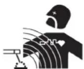
ELECTRODE GRINDING
To optimise the welding process, it is recommended to grind the electrode prior to welding as described below:
text_image
d LL = 3 x d for a low current.
L = 3 x d for a high current
TROUBLESHOOTING
| Problem Cause SOLUTION | |||
| The machine does not start, there is no communication. | The installation is defective (the fuses, the circuit breakers or the differential are defective). | Check the power supply network and replace, if necessary, the faulty protections. | |
| The 200A source does not answer to the automaton. | The communication CAN OPEN between the automaton and the power supply does not happen. | Check the wired connection, the wiring direction and the pins allocation.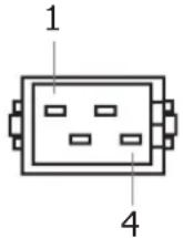 1- GND (0 Vdc)2- CAN_LOW3- CAN_HIGH4- GND (0 Vdc) 1- GND (0 Vdc)2- CAN_LOW3- CAN_HIGH4- GND (0 Vdc) | ref. 012448 |
 1- N.C2- CAN_LOW3- CAN_GND4- N.C5- CAN_SHIELD6- GND (0 Vdc)7- CAN_HIGH8- CAN_V+ (N.C)9- N.C 1- N.C2- CAN_LOW3- CAN_GND4- N.C5- CAN_SHIELD6- GND (0 Vdc)7- CAN_HIGH8- CAN_V+ (N.C)9- N.C | ref. 075221 | ||
| The 200A source does not answer to the automaton. | The communication CAN OPEN between the automaton and the power supply does not happen. |  Bit [1;3] : Baud rate = 250 Kbit/s (100b)Bit [4;8] : Object address = 10 (01010b) Bit [1;3] : Baud rate = 250 Kbit/s (100b)Bit [4;8] : Object address = 10 (01010b) | |
| The 200A source is power up but it no longer delivers power. | The thermal protection has switched on. | Wait for the end of the thermical protection during 3 minutes max. | |
| The 200A source is power up but the machine does not weld. | Fault with earth clamp/cable connection. | Check the connections of the cables and clamps. | |
| The 200A source is power up, you are feeling tingling when touching the case. | No earth continuity. | Multimeter on position « Ohmmeter » Unplugged source, control the earth continuity between the machine and the mains cable.The measured resistance must be low (short-circuit)If OKCheck our electrical installation by a professional. | |
| The 200A source is power up but the machine does not weld well. | Polarity error (+/-). | Check the polarity (+/-). | |
WARRANTY
The warranty covers faulty workmanship for 2 years from the date of purchase (parts and labour).
The warranty does not cover:
- Transit damage.
- Normal wear of parts (eg. : cables, clamps, etc..).
- Damages due to misuse (power supply error, dropping of equipment, disassembling).
- Environment related failures (pollution, rust, dust).
In case of failure, return the unit to your distributor together with:
- The proof of purchase (receipt etc ...)
- A description of the fault reported

WAARSCHUWING - VEILIGHEIDSINSTRUCTIES
ALGEMENE INSTRUCTIES

INSTALLATIE VAN HET APPARAAT
text_image
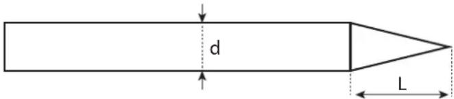
Exploded view diagram of an electronic device with numbered parts for identification| DÉSIGNATION 012448 075221 | |||
| 1 | Embase Texas H21 femelle / Pinhead adaptor H21 female CX0031 / Texas-Buchse T50 CX0031 / Conector mujer Texas H21 / Гнездо «женщина» Texas h21 / Vrouwelijk fitting Texas H21 / Connettore femminile Texas H21 | 51461 | |
| 2 | Transformateur HF / HF transformer / Trafo HF / Transformador HF / Трансформатор ВЧ / Transformator HF / Trasformatore HF | 96130 | |
| 3 | Circuit source de courant 200A / Welding machine circuit 200A / Stromkreisquelle 200 A / Circuito de fuente de corriente de 200A / Плата источника тока 200A / Circuit stroombron 200A / Circuito sorgente di corrente 200A | 97388C | |
| 4 | Self PFC / Self PFC / PFC-Drossel / Inductancia PFC / Дроссель PFC / Inductie PFC | 63691 | |
| 5 | Circuit bridge CAN OPEN / CAN OPEN bridge circuit / Schaltungsbrücke CAN OPEN / Circuito puente CAN OPEN / Схема BRIDGE CAN OPEN / Bridge circuit CAN open / Circuito ponte CAN OPEN | 97378C E0133C | |
| 6 | Passe-fil borgne PVC / Wire-guide PVC / Drahtdurchführungstülle mit Sackloch aus PVC / Pasacable ciego PVC / Глухой нитепроводник из ПВХ / Kabelring PVC / Passa-filo cieco PVC | 43123 | |
| 7 | Cordon secteur / Power supply cable / Netzkabel / Cable de conexión eléctrica / Сетевой шнур / Elektrische netsnoer / Cavo corrente | 91869 F0928 | |
| 8 | Carte CEM / CEM board / EMV-Platine / Tarjeta CEM / Плата CEM / Printplaat / Carta CEM | 63886IND1 | |
| 9 | Grille de protection / Protection grill / Schutzgitter / Rejilla de protección / Защитная решетка / Bescher-mingsrooster / Griglia di protezione | 51010 | |
| 10 | Ventilateur 24V 120x120 / 24V fan 120x120 / Lüfter 24V, 120x120 / Ventilador 24V 120x120 / Вентилятор 24B 120x120 / Ventilator 24V 120x120 / Ventilatore 24V 120x120 | 51021 | |
| 11 | Silent bloc Elastique / Silent elastic block / Elastischer Stoßdämpfer / Silentbloc elástico / Эластичная резинометаллическая втулка / Silent bloc Elastique / Blocco silenziatore Elastico | 71142 | |
SCHÉMA ÉLECTRIQUE / CIRCUIT DIAGRAM /SCHALTPLAN/ DIAGRAMA ELECTRICO /ЭЛЕКТРИЧЕСКАЯ СХЕМА / ELEKTRISCHE SCHEMA / SCEMA ELETTRICO
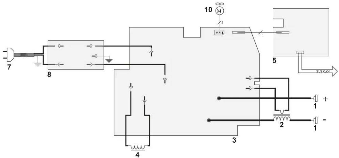
text_image
7 8 10 M 2 10 5 BUS CAN 4 3 2 + - 1 1ICÔNES / SYMBOLS / ZEICHENERKLÄRUNG / SÍMBOLOS / СИМВОЛЫ / PICTOGRAMMEN / ICONA
 | - Attention ! Lire le manuel d'instruction avant utilisation. - Caution ! Read the user manual. - Achtung! Lesen Sie die Betriebsanleitung. - Cuidado, leer las instrucciones de utilización. - Внимание ! Читайте инструкцию по использованию. - Let op! Lees voorzichtig de gebruiksaanwijzing. - Attenzione! Leggere il manuale d'istruzioni prima dell'uso. |
| 1~20000000000000000000000000000000000000000000000000000000000000000000000000000000000000000000000000000 | Source de courant de technologie onduleur délivrant un courant continu. - Undulating current technology based source delivering direct curent. - Invertergleichstromquelle. - Fuente de corriente de tecnología ondulador que libera corriente continua.- Источник тока с технологией преобразователя, выдающий постоянный ток. - Stroombron met UPS technologie, levert gelijkstroom. - Fonte di corrente con tecnologia inverter che rilascia una corrente continua. |
 | Soudage TIG (Tungsten Inert Gaz)TIG – welding (Tungsten Inert Gas) – Schweißen mit Wolfram Elektrode (Wolfram Edelgas) – Soldadura TIG (Tungsten Inert Gaz) – Сварка TIG (Tungsten Inert Gaz) – Saldatura TIG (Tungsten Inert Gaz) – TIG lassen (Tungsten Inert Gaz) |
 | - Convient au soudage dans un environnement avec risque accru de choc électrique. La source de courant elle-même ne doit toutefois pas être placée dans de tels locaux. - Adapted for welding in environments with increased risk of electrical shock. However, the welding machine should not be placed in such places. - Geeignet für Schweißarbeiten im Bereich mit erhöhten elektrischen Risiken. Trotzdem sollte die Schweißquelle nicht unbedingt in solchen Bereichen betrieben werden. - Adaptado a la soldadura en un entorno que comprende riesgos de choque eléctrico. La fuente de corriente ella misma no debe estar situada dentro de tal locales. - Подходит для сварки в среде с повышенной опасностью удара электрическим током. Тем не менее не следует ставить источник тока в такие помещения. - Geschikt voor het lassen in een ruimte met verhoogd risico op elektrische schokken. De voedingsbron zelf moet echter niet in dergelijke ruimte worden geplaatst. - È consigliato per la saldatura in un ambiente con grandi rischi di scosse elettriche. La fonte di corrente non deve essere localizzata in tale posto. |
 | Courant de soudage continu - Welding direct current - Gleichschweissstrom - La corriente de soldadura es continua - Сварка на постоянном токе - Continue lasstroom -Corrente di saldatura continua |
| Uo | Tension assignée à vide - Rated no-load voltage - Leerlaufspannung - Tensión asignada de vacío - Напряжение холостого хода -Nullastspanning - Tensione nominale a vuoto |
| X(40°C) | Facteur de marche selon la norme IEC 60974-1 (10 minutes – 40°C). - Duty cycle according to standard IEC 60974-1 (10 minutes – 40°C). - Einschaltdauer: 10 min - 40°C, richtlinienkonform IEC 60974-1. - Ciclo de trabajo según la norma IEC 60974-1 (10 minutos – 40°C). - ПВ% согласно норме IEC 60974-1 (10 минут – 40°C). - Inschakelduur volgens de norm IEC 60974-1 (10 minuten – 40°C). - Ciclo di lavoro conforme alla norma IEC 60974-1 (10 minuti – 40°C). |
| I2 | I2 : courant de soudage conventionnel correspondant - I2 : corresponding conventional welding current - I2 : entsprechender Schweißstrom - I2 : Corrientes correspondientes - I2 : Соответствующий условный сварочный ток - I2 : overeenkomstige conventionele lasstroom - I2 : corrente di saldatura convenzionale corrispondente |
| A | Ampères - Amps - Ampere - Amperio - Amper - Ampère - Amper |
| U2 | U2 : Tensions conventionnelles en charges correspondantes - U2 : conventional voltages in corresponding load - U2 : entsprechende Arbeitsspannung - U2 : Tensiones convencionales en carga - U2 : Соответствующие условные напряжения под нагрузкой - U2 : conventionele spanning in corresponderende belasting - U2 : Tensioni convenzionali in cariche corrispondenti |
| V | Volt - Volt - Volt - Voltios - Вольт - Volt - Volt |
| Hz | Hertz - Hertz - Hertz - Hertz - Герц - Hertz - Hertz |
| 1~50-60 Hz | - Alimentation électrique monophasée 50 ou 60Hz - Single phase power supply 50 or 60Hz - Einphasige Netzversorgung mit 50 oder 60Hz - Alimentación eléctrica monofásica 50 o 60 Hz - Однофазное напряжение 50 или 60Гц - Enkel fase elektrische voeding 50Hz of 60Hz - Alimentazione elettrica monofase 50 o 60Hz |
| U1 | Tension assignée d'alimentation - rated supply voltage - Netzspannung - Tensión de la red - Напряжение сети - Nominale voedingsspanning - Tensione nominale d'alimentazione |
| I1max | - Courant d'alimentation assigné maximal (valeur efficace) - Rated maximum supply current (effective value) - Maximaler Versorgungsstrom (Effektivwert) - Corriente maxima de alimentacion de la red - Максимальный сетевой ток (эффективная мощность) - Maximale nominale voedingsstroom (effectieve waarde) - Corrente d'alimentazione nominale massima (valore effettivo) |
| I1eff | - Courant d'alimentation effectif maximal - Maximum effective supply current - Maximaler tatsächlicher Versorgungsstrom- Corriente de alimentación efectiva maxima - Максимальный эффективный сетевой ток - Maximale effectieve voedingsstroom- Corrente di alimentazione massima effettiva |
CE | - Appareil conforme aux directives européennes. La déclaration de conformité est disponible sur notre site internet. - The device complies with European Directive. The certificate of compliance is available on our website. - Gerät entspricht europäischen Richtlinien. Die Konformitätserklärung finden Sie auf unsere Webseite. - El aparato está conforme a las normas europeas. La declaración de conformidad está disponible en nuestra página Web. - Устройство соответствует европейским нормам. Декларация соответствия есть на нашем сайте. - Het toestel is in overeenstemming met de Europese richtlijnen. De conformiteitsverklaring is te vinden op onze internetsite. - Dispositivo in conformità con le norme europee. La dichiarazione di conformità è disponibile sul nostro sito internet.- Matériel conforme aux normes Marocaines. La déclaration C_o (CMIM) de conformité est disponible sur notre site (voir à la page de couverture).- Equipment in conformity with Moroccan standards. The declaration C_o (CMIM) of conformity is available on our website (see cover page).- Das Gerät entspricht die marokkanischen Standards. Die Konformitätserklärung C_o (CMIM) ist auf unserer Webseite verfügbar (siehe Titelseite).- Equipamiento conforme a las normas marroquíes. La declaración de conformidad C_o (CMIM) está disponible en nuestra página web (ver página de portada).- Товар соответствует нормам Марокко. Декларация C_o (CMIM) доступна для скачивания на нашем сайте (см на титульной странице).- Dit materiaal voldoet aan de Marokkaanse normen. De verklaring C_o (CMIM) van overeenstemming is beschikbaar op onze internet site (vermeld op de omslag).- Materiale conforme alle normative marocchine. La dichiarazione C_o (CMIM) di conformità è disponibile sul nostro sito (vedi scheda del prodotto) |
| IEC 60974-1IEC 60974-10Class A | - L'appareil respecte les normes IEC 60974-1, IEC 60974-10 et Class A - The device complies with IEC 60974-1, IEC 60974-10, Class A standard relative to welding units - Das Gerät entspricht der Norm IEC 60974-1, IEC 60974-10, Class A für Schweißgeräte - El aparato está conforme a la norma IEC 60974-1, IEC 60974-10, Class A referente a los aparatos de soldadura - Аппарат соответствует европейской норме IEC 60974-1, IEC 60974-10, Class A - Dit toestel voldoet aan de IEC 60974-1, IEC 60974-10, Class A norm.- Il dispositivo rispetta la norma IEC 60974-1, IEC 60974-10, Class A. |
| IEC60974-3 | - L'appareil respecte les normes IEC 60974-3- The device complies with IEC 60974-3 standard relative to welding units - Das Gerät entspricht der Norm IEC 60974-3 für Schweißgeräte - El aparato está conforme a la norma IEC 60974-3 referente a los aparatos de soldadura - Аппарат соответствует европейской норме IEC 60974-3 - Dit toestel voldoet aan de IEC 60974-3 norm - Il dispositivo rispetta la norma IEC 60974-3. |
 | - Ce matériel faisant l'objet d'une collecte sélective selon la directive européenne 2012/19/UE. Ne pas jeter dans une poubelle domestique ! - This hardware is subject to waste collection according to the European directives 2012/19/EU. Do not throw out in a domestic bin ! - Für die Entsorgung Ihres Gerätes gelten besondere Bestimmungen (sondermüll) gemäß europäische Bestimmung 2012/19/EU. Es darf nicht mit dem Hausmüll entsorgt werden! - Este material requiere una recogida de basuras selectiva según la directiva europea 2012/19/UE. iNo tirar este producto a la basura doméstica! - Это оборудование подлежит переработке согласно директиве Евросоюза 2012/19/UE. Не выбрасывать в общий мусоросборник! - Afzonderlijke inzaming vereist volgens de Europese richtlijn 2012/19/UE. Gooi het apparaat niet bij het huishoudelijk afval ! - Questo materiale è soggetto alla raccolta differenziata seguendo la direttiva europea 2012/19/UE. Non smaltire coni rifiuti domestici! |
| UKCA | - Matériel conforme aux exigences britanniques. La déclaration de conformité britannique est disponible sur notre site (voir à la page de couverture).- Equipment in compliance with British requirements. The British Declaration of Conformity is available on our website (see home page).- Das Gerät entspricht den britischen Richtlinien und Normen. Die Konformitätserklärung für Grossbritannien ist auf unserer Internetseite verfügbar (siehe Titelseite).- Equipo conforme a los requisitos británicos. La Declaración de Conformidad Británica está disponible en nuestra página web (véase la portada).- Материал соответствует требованиям Великобритании. Заявление о соответствии для Великобритании доступно на нашем веб-сайте (см. главную страницу).- Materiaal conform aan de Britse eisen. De Britse verklaring van overeenkomt is beschikbaar op onze website (zie omslagpagina).- Materiale conforme alla esigenze britanniche. La dichiarazione di conformità britannica è disponibile sul nostro sito (vedere pagina di copertina). |
 | - Produit recyclable qui relève d'une consigne de tri - This product should be recycled appropriately - Produkt muss getrennt ensorgt werden. Werfen Sie das Gerät nicht in den Hausmüll. - Producto reciclable que requiere una separación determinada. - Этот аппарат подлежит утилизации - Product recyclebaar, niet bij het huishoudelijk afval gooien - Prodotto riciclabile che assume un ordine di smistamento |
 | - Marque de conformité EAC (Communauté économique Eurasienne) - Conformity mark EAC (Eurasian Economic Commission) - EAC-Konformitätszeichen (Eurasische Wirtschaftsgemeinschaft) - Marca de conformidad EAC (Comunidad económica euroasiática) - Маркировка соответствия EAC (Евразийское экономическое сообщество) - EAC (Euraziatische Economische Gemeenschap) merkteken van overeenstemming. - Marca di conformità EAC (Comunità Economica Eurasiatica) |
| ### | - Information sur la température (protection thermique) - Thermal protection information - Information zur Temperatur (Thermoschutz) - Información de la temperatura (protección térmica) - Информация по температуре (термозащита) - - Informatie over de temperatuur (thermische beveiliging) - Informazione sulla temperatura (protezione termiche) |

