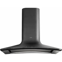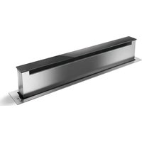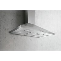
Arezzo EAR634SS - Basket ELICA - Free user manual and instructions
Find the device manual for free Arezzo EAR634SS ELICA in PDF.


User questions about Arezzo EAR634SS ELICA
0 question about this device. Answer the ones you know or ask your own.
Ask a new question about this device
Download the instructions for your Basket in PDF format for free! Find your manual Arezzo EAR634SS - ELICA and take your electronic device back in hand. On this page are published all the documents necessary for the use of your device. Arezzo EAR634SS by ELICA.
USER MANUAL Arezzo EAR634SS ELICA
natural_image
Isometric technical drawing of a mechanical component with a central circular component and two rectangular bases (no text or symbols)Use, Care, and Installation Guide
READ AND SAVE THESE INSTRUCTIONS
LISEZ CES INSTRUCTIONS ET CONSERVEZ-LES
LEA Y CONSERVE ESTAS INSTRUCCIONES
LIB0140797A Printed in Mexico 08/19
Models: ETR134S1
EAR628S4
EAR134S4
EAR140S4
EAR146S4
ENGLISH
Contents
Important safety notice....3
Electrical & installation requirements 4
Before installing the hood 4
Product dimensions 4
List of materials....5
Parts supplied 5
Parts not supplied 5
Ducting options and examples.... 6
Installation 8
Electrical connection....9
Complete the installation....9
Description of the hood....9
Control....9
Maintenance 10
Warranty 11
APPROVED FOR RESIDENTIAL APPLIANCES
READ AND SAVE THESE INSTRUCTIONS
PLEASE READ ENTIRE INSTRUCTIONS BEFORE PROCEEDING.
INSTALLATION MUST COMPLY WITH ALL LOCAL CODES.
IMPORTANT: Save these Instructions for the Local Electrical Inspector's use.
INSTALLER: Please leave these Instructions with this unit for the owner.
OWNER: Please retain these instructions for future reference.
Safety Warning: Turn off power circuit at service panel and lock out panel, before wiring this appliance.
Requirement: 120 V AC, 60 Hz. 15 or 20 A Branch Circuit.

IMPORTANT SAFETY NOTICE
CAUTION
FOR GENERAL VENTILATING USE ONLY. DO NOT USE TO EXHAUST HAZARDOUS OR EXPLOSIVE MATERIALS AND VAPOURS.
⚠ WARNING
TO REDUCE THE RISK OF FIRE, ELECTRIC SHOCK, OR INJURY TO PERSONS, OBSERVE THE FOLLOWING:
A. Use this unit only in the manner intended by the manufacturer. If you have questions, contact the manufacturer.
B. Before servicing or cleaning unit, switch power off at service panel and lock service panel to prevent power from being switched on accidentally.
When the service disconnecting means cannot be locked, securely fasten a prominent warning device, such as a tag, to the service panel.
C. Installation work and electrical wiring must be done by qualified person(s) in accordance with all applicable codes & standards, including fire-rated construction.
D. Sufficient air is needed for power combustion and exhausting of gases through the flue (Chimney) of fuel burning equipment to prevent back- drafting.
Follow the heating equipment manufacturers guideline and safety standards such as those published by the national fire protection association (NFPA), the american society for heating, refrigeration and air conditioning engineers (ASHRAE), and the local code authorities.
E. When cutting or drilling into wall or ceiling, do not damage electrical wiring and other hidden utilities.
F. Ducted fans must always vented to the outdoors.
CAUTION
To reduce risk of fire and to properly exhaust air, be sure to duct air outside - do not vent exhaust air into spaces within walls, ceilings, attics, crawl spaces, or garages.
⚠ WARNING
TO REDUCE THE RISK OF FIRE, USE ONLY METAL DUCT WORK.
Install this hood in accordance with all requirements specified.
⚠ WARNING
To Reduce The Risk Of Fire Or Electric Shock, Do Not Use This Fan With Any Solid-State Speed Control Device.
⚠ WARNING
To Reduce The Risk Of Fire And Electric Shock, Install This Rangehood Only With Integral, In Line, and External Blower Models Rated Maximum 7.7 A/ 926 W, Or Integral Blowers Manufactured by Elica (for model references, see optional accessories table).
| Integral Blower(already included with the hood) | In LineBlower Kit 1200KIT0154387 | ExternalBlower Kit 1200KIT0153054 | ||||
| HOOD MODEL | A | W | A | W | A | W |
| EAR628S4 | 3.9 | 463 | 7.7 | 454 | 7.4 | 884 |
| ETR134S1 | 7.6 | 913 | 7.6 | 913 | 7.4 | 884 |
| EAR140S4 | 7.7 | 926 | 7.7 | 926 | 7.5 | 897 |
| EAR140S4 | 7.7 | 926 | 7.7 | 926 | 7.5 | 897 |
| EAR134S4 | 7.6 | 913 | 7.6 | 913 | 7.4 | 884 |
⚠ WARNING
TO REDUCE THE RISK OF A RANGE TOP GREASE FIRE.
a) Never leave surface units unattended at high settings. Boilovers cause smoking and greasy spillovers that may ignite. Heat oils slowly on low or medium settings.
b) Always turn hood ON when cooking at high heat or when flambeing food (i.e. Crepes Suzette, Cherries Jubilee, Peppercorn Beef Flambe').
c) Clean ventilating fans frequently. Grease should not be allowed to accumulate on fan or filter.
d) Use proper pan size. Always use cookware appropriate for the size of the surface element.
⚠ WARNING
TO REDUCE THE RISK OF INJURY TO PERSONS, IN THE EVENT OF A RANGE TOP GREASE FIRE, OBSERVE THE FOLLOWING: ^4
a) SMOTHER FLAMES with a close-fitting lid, cookie sheet, or metal tray, then turn off the gas burner or the electric element. BE CAREFUL TO PREVENT BURNS. If the flames do not go out immediately, EVACUATE AND CALL THE FIRE DEPARTMENT.
b) NEVER PICK UP A FLAMING PAN - you may be burned.
c) DO NOT USE WATER, including wet dishcloths or towels - a violent steam explosion will result.
d) Use an extinguisher ONLY if:
1) You know you have a class ABC extinguisher, and you already know how to operate it.
2) The fire is small and contained in the area where it started.
3) The fire department is being called.
4) You can fight the fire with your back to an exit.
^a Based on "Kitchen Fire Safety Tips" published by NFPA.
CAUTION
Automatically Operated Device - To reduce the risk of Injury disconnect from power supply before servicing.
ELECTRICAL & INSTALLATION REQUIREMENTS
IMPORTANT
Observe all governing codes and ordinances. It is the customer's responsibility:
• To contact a qualified electrical installer.
- To assure that the electrical installation is adequate and in conformance with National Electrical Code, ANSI/NFPA 70 — latest edition*, or CSA Standards C22.1-94, Canadian Electrical Code, Part 1 and C22.2 No.0-M91-latest edition** and all local codes and ordinances.
- If codes permit and a separate ground wire is used, it is recommended that a qualified electrician determine that the ground path is adequate.
- Do not ground to a gas pipe.
- Check with a qualified electrician if you are not sure range hood is properly grounded.
- Do not have a fuse in the neutral or ground circuit.
IMPORTANT
- Save Installation Instructions for electrical inspector's use.
- The range hood must be connected with copper wire only.
- The range hood should be connected directly to the fused disconnect (Or circuit breaker) box through metal electrical conduit.
- Wire sizes must conform to the requirements of the National Electrical Code ANSI/NFPA 70 — latest edition*, or CSA Standards C22.1-94, Canadian Electrical Code Part 1 and C22.2 No. O-M91 - latest edition** and all local codes and ordinances.
- A U.L.- or C.S.A.-listed conduit connector must be provided at each end of the power supply conduit (at the range hood and at the junction box).
Copies of the standards listed may be obtained from:
* National Fire Protection Association Batterymarch Park Quincy, Massachusetts 02269
** CSA International 8501 East Pleasant Valley Road Cleveland, Ohio 44131-5575
BEFORE INSTALLING THE HOOD
1 For the most efficient air flow exhaust, use a straight run or as few elbows as possible.
CAUTION: Vent unit to outside of building, only.
2 At least two people are necessary for installation.
3 Fittings material is provided to secure the hood to most types of walls/ceilings, consult a Qualified Installer, check if they perfectly fit with your cabinet/wall.
4 Do not use flex ducting.
5 COLD WEATHER installations should have an additional backdraft damper installed to minimize backward cold air flow and a nonmetallic thermal break to minimize conduction of outside temperatures as part of the ductwork. The damper should be on the cold air side of the thermal break.
The break should be as close as possible to where the ducting enters the heated portion of the house.
6 Make up air: Local building codes may require the use of Make-Up Air Systems when using Ducted Ventilation Systems greater than specified CFM of air movement. The specified CFM varies from locale to locale. Consult your HVAC professional for specific requirements in your area.
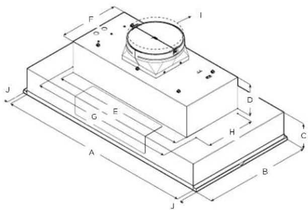
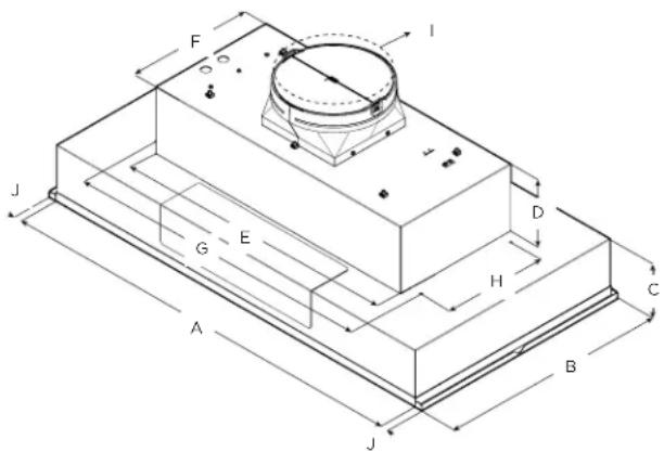
PRODUCT DIMENSIONS
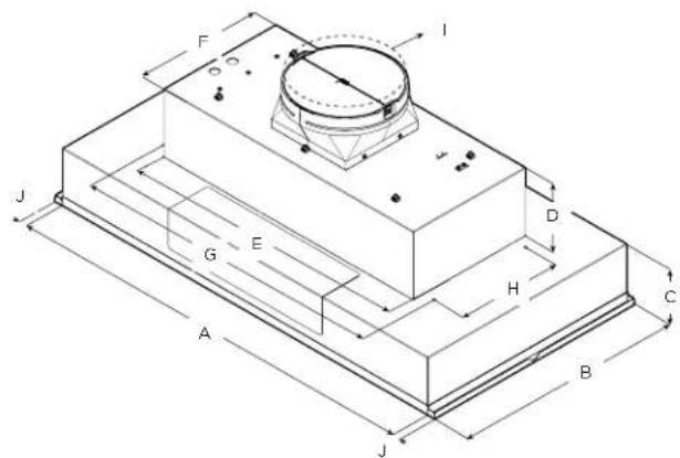
text_image
F I J G E D H C A B J| Models | |||||
| EAR628S4 | ETR134S1 | EAR134S4 | EAR140S4 | EAR146S4 | |
| A | 28 12 " (72.4 cm) | 34 12 " (87.6 cm) | 40 12 " (103 cm) | 46 12 " (118 cm) | |
| B | 22" (55.9 cm) | 18" (45.7 cm) | 22" (55.9 cm) | ||
| C 5 | 316" (13.8 cm) | ||||
| D 6 | 12" (16.4 cm) | ||||
| E 27 | 316" (70 cm) | ||||
| F | 12 116" (31.6 cm) | ||||
| G | 29 116" (75.7 cm) | ||||
| H | 10 18" (25.7 cm) | ||||
| I | 10" (25.4 cm) | ||||
| J | 34" (1.9 cm) | ||||
LIST OF MATERIALS
Removing the packaging.
CAUTION
Remove carton carefully, Wear gloves to protect against sharp edges.
WARNING
Remove the protective film covering the product before putting into operation.
| Supplied Part Pieces Supplied Part Pieces | |||
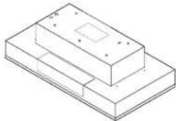 Hood assembly with blower andLED lamps already installed Hood assembly with blower andLED lamps already installed | 1 | 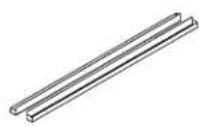 Side spacers Side spacers | 2 |
 5x45 mm 5x45 mm | 4 | 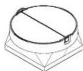 10" round air transition 10" round air transition | 1 |
| 4x8 mm | 10 | ||
Parts no supplied
Tools/Materials required
- Level
- Drill
- 1 14 (3 cm) drill bit
- 1/8'' (3 mm) drill bit
- Pencil
- Wire stripper or knife
- Tape measure or ruler
- Pliers
- Caulking gun and weatherproof caulking compound
- Vent clamps
• Jigsaw or keyhole saw - Flat-blade screwdriver
- Metal snips
• Phillips screwdriver
Parts needed
• Home power supply cable
- 1 - 12 " (12.7 mm) UL listed or CSA approved strain relief
• 3 UL listed wire connectors
- 1 wall or roof cap
- Metal vent system
Optional accessories and consumable parts
| KIT # Part | |
| EAR628S4, ETR134S1, EAR140S4, EAR146S4, EAR134S4 | |
| in Line Blower 1200 Kit | KIT0154387 |
| External Blower 1200 Kit | KIT0153054 |
Ducting Options
Closely follow the instructions set out in this manual. All responsibility, for any eventual inconveniences, damages or fires caused by not complying with the instructions in this manual, is declined.
Preparation
Do not cut a joist or stud unless absolutely necessary. If a joist or stud must be cut, then a supporting frame must be constructed.
Fittings material is provided to secure the hood to most types of walls/ceilings.
However, a qualified technician must verify suitability of the materials in accordance with the type of wall/ceiling.
Before making cutouts, make sure there is proper clearance within the ceiling or wall for exhaust vent.
The hood is equipped with an 10" (25.4 cm) round transition for discharge of fumes to the outside.
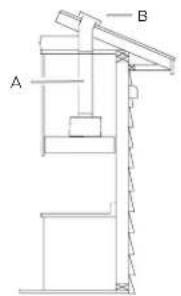
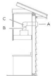
Roof Venting Wall Venting
text_image
A BG. 10" (25.4 cm) round vent H. Wall cap
text_image
C B AA. Wall cap
B. 10" (25.4 cm) round vent
C. 90^ elbow
CAUTION
For gas cooktop & range installations: Mount the hood so the bottom is at least 30" (76.2 cm) above the cooking surface.
For electric/induction cooktop & range installations: Mount the hood so the bottom is at least 24" (61 cm) above the cooking surface.
There is no maximum mounting height, however, we recommend mounting the hood no greater than 36" (91.4 cm) above the cooking surface. For every inch (2.54 cm) above 36" (91.4 cm), fume and moisture capture efficiency diminishes at an increasing rate and may not deliver an acceptable level of ventilating performance.
This hood is intended for household use.
PLEASE READ THE INSTALLATION MANUAL FOR SPECIFIC APPLICATION. Check your ceiling height and hood height before selecting your hood.
Prepare the Location
- Disconnect power.
- Determine which venting method to use: roof or wall exhaust.
- Select a flat surface for assembling the hood insert. Place covering over that surface.
- It is recommended that the vent system be installed before hood is installed.
- Before making cutouts, make sure there is proper clearance within the ceiling or wall for exhaust vent.
- Hood insert should be installed a minimum 24" (61 cm) above an electric cooktop surface and 30" (76.2 cm) above a gas cook top surface. The maximum recommended height over both cook tops is 36" (91.44 cm).
- Check that all installation parts have been removed from the shipping carton.
• Using 2 or more people, lift hood insert onto covered surface. - Remove the filters. See the "Cleaning" section.
Dimensions and Clearances
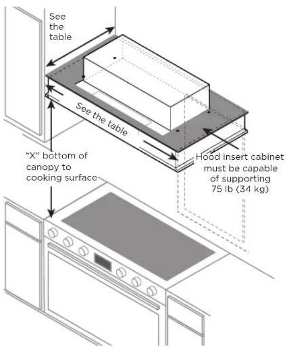
This range hood has the flexibility to be installed in two different ways, depending on the width measurement or working area between the left and right cabinetry. Before beginning, it is important to determine the dimension of this working area and to consider the measurements detailed in the next table.
| Range Hood Models | Range Hood width without spacers | Range Hood width with spacers | Range Depth |
| EAR628S4 | 28 12 " (72 cm) | 30" (76.2 cm) | 22" (55.9 cm) |
| EAR134S4 | 34 12 " (87 cm) | 36" (91.44 cm) | |
| EAR140S4 | 40 12 " (102 cm) | 42" (106.68 cm) | |
| EAR146S4 | 46 12 " (117.5 cm) | 48" (121.92 cm) | |
| ETR134S1 | 34 12 " (87 cm) | 36" (91.44 cm) | 18" (45.7 cm) |
text_image
See the table See the table "Hood insert cabinet must be capable of supporting 75 lb (34 kg) "X" bottom of canopy to cooking surfaceIMPORTANT: Minimum distance "X": 24" (61 cm) from electric cooking surfaces. Minimum distance "X": 30" (76.2 cm) from gas cooking surfaces.
Stainless Steel Hood Spacer Installation
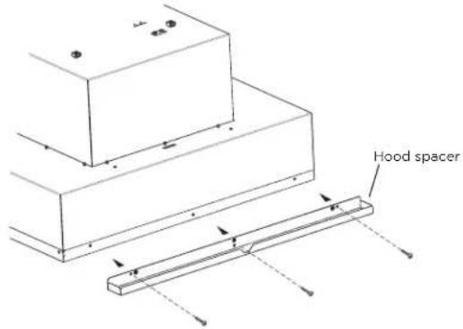
- You can elongate 1.5" (3.8 cm) of your range hood width ( 34 " [1.9 cm] per side), installing the stainless steel spacers included with your range hood.
- Unpack the spacer and take off the protective.
- Put each one on the right and the left side
- Fasten hood spacer using four 5 x 45 mm screws to the hood cabinet and tighten securely.
text_image
Hood spacer- If cabinetry designs reduces the width opening (i.e. - 28.5", 34.5", 40.5" or 46.5") to install the hood, the spacers are not used.
- If you have a Full width opening (i.e. - 30", 36", 42" or 48") to install the hood, you should use the spacers.
Install Range Hood into Hood Cabinet
The range hood attaches to the hood cabinet using four mounting screws and washers. NOTE: Hood cabinet must be capable of supporting 75 lb (34 kg).
Prepare Range hood for mounting into cabinet
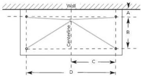
- Mark the locations for the four mounting screws on the hood cabinet as shown below.
- Using a 18 " (3 mm) drill bit, drill the 4 holes.
text_image
Wall Centerline A B C DMOUNTING HOLE DIMENSIONS
| EAR628S4 | 6"(15.5 cm) | 10%"(25.6 cm) | 12%"(30.9 cm) | 24%"(61.8 cm) | ∅1⁄2"(3mm) |
| EAR134S4 | 14%"(38 cm) | 29%"(75.8 cm) | |||
| EAR140S4 | |||||
| EAR146S4 | |||||
| ETR134S1 | 2"(5 cm) |
- Mark the cutout for the rectangular clearance hole for the upper range hood motor housing as shown.
- Using a jigsaw or keyhole saw, cut out the rectangular clearance hole for the upper range hood housing.

text_image
Wall Centerline A B C DUPPERHOOD MOTOR HOUSING DIMENSIONS
| Model DIM A DIM B DIM C DIM D | ||||
| EAR628S4 | 414 " (10.8 cm) | 1518 " (38.9 cm) | 718 " (19.45 cm) | 2318 " (59.5 cm) |
| EAR134S4 | ||||
| EAR140S4 | 1412 " (36.8 cm) | 2818 " (73.5 cm) | ||
| EAR146S4 | ||||
| ETR134S1 | ||||
Install the range hood into the hood cabinet
- Determine and make all necessary cuts in the wall or roof for the vent system. Install the vent system before installing the cabinet hood insert. See the "Venting Requirements" section.
- Determine the location where the power supply cable will be run through the wall.
- Drill a 1¼" (3.2 cm) hole at this location.
- Pull enough power supply cable through the wall to allow for easy connection to the terminal box.
- Remove terminal box cover and set aside.
- Install the 10" (25.4 cm) square x 10" (25.4 cm) round vent transition with damper to top side of the range hood, using 4 - 3.5 x 9.5 mm screws.
- Remove knockout from the top of the vent hood and install a UL listed or CSA approved 12 " (1.3 cm) strain relief.
- Place the hood insert near its mounting position and run the power supply cable through the strain relief into terminal box (enough to make connection).
- Tighten the strain relief screws.
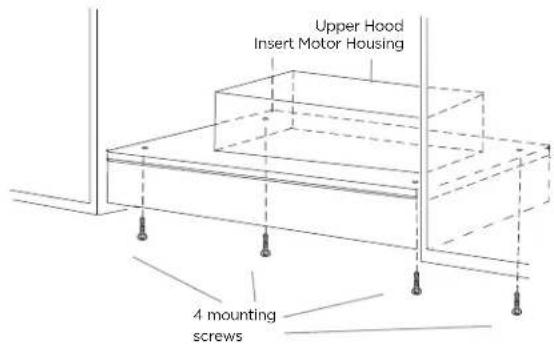
- Using 2 or more people, lift the hood insert into hood cabinet.
- Fasten the hood insert using four 5 x 45 mm screws to the hood cabinet and tighten securely.
⚠ WARNING
EXCESSIVE WEIGHT HAZARD
USE TWO OR MORE PEOPLE TO MOVE AND INSTALL HOOD INSERT.
FAILURE TO DO SO CAN RESULT IN BACK OR OTHER INJURY.
text_image
Upper Hood Insert Motor Housing 4 mounting screwsElectrical Connection
⚠ WARNING
ELECTRICAL SHOCK HAZARD.
⚠ WARNING
DISCONNECT POWER BEFORE SERVICING. REPLACE ALL PARTS AND PANELS BEFORE OPERATING. FAILURE TO DO SO CAN RESULT IN DEATH OR ELECTRICAL SHOCK.
- Disconnect power.
- Locate terminal box inside of the hood insert.
text_image
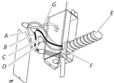
Technical diagram of a mechanical assembly with labeled components A through G and directional arrows indicating motion or force.A. White wires
B. Black wires
C. UL listed wire connectors
D. Green, bare or yellow/green wires
E.Home power supply
F. UL listed or CSA approved 1/2" (1.3
cm) strain relief
G. Ground Wire tab
-
Use UL listed wire connectors and connect black wires (B) together.
-
Use UL listed wire connectors and connect white wires (A) together.
WARNING
ELECTRICALLY GROUND BLOWER. CONNECT GROUND WIRE TO GREEN AND YELLOW GROUND WIRE IN TERMINAL BOX. FAILURE TO DO SO CAN RESULT IN DEATH OR ELECTRICAL SHOCK.
- Connect green (or bare) ground wire from home power supply to the green/yellow ground wire (D) in terminal box using UL listed wire connectors.
- Install terminal box cover.
- Check that all light bulbs are secure in their sockets.
- Reconnect power.
Complete Installation
- Install grease filters. See the "Cleaning" section.
- Check operation of the Hood Insert blower and lights. See the "Hood Insert Use" section.
- If the hood insert does not operate, check to see whether a circuit breaker has tripped or a household fuse has blown.
Disconnect power supply and check that the wiring is correct.
NOTE: To get the most efficient use from your new hood insert, read the "Hood Insert Use" section.
Description of the Hood
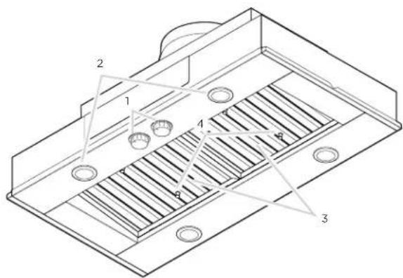
text_image
Technical diagram of a mechanical component with numbered parts and measurement indicators- Blower and light controls
-
LED lamps
-
Grease filter handle
- Grease filter
Control
The range hood is designed to remove smoke, cooking vapors and odors from the cooktop area. For best results, start the hood before cooking and allow it to operate several minutes after the cooking is complete to clear all smoke and odors from the kitchen.
The hood controls are located on the center side of the range hood.
Recessing Knobs
- You can hide control knobs by depressing them until flush with the hood body.
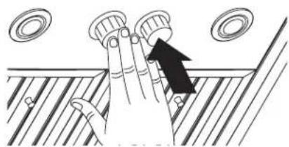
natural_image
Diagram showing hand pressing down on a surface with rollers above (no text or symbols)- Pressing the knobs again will lower the knobs, and enable the user to operate the lights and blower.
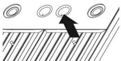
natural_image
Diagram showing a black arrow pointing to circular features on a textured surface with diagonal lines and small markers (no text or symbols)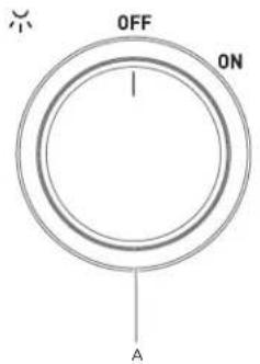
text_image
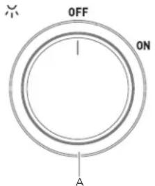
OFF ON A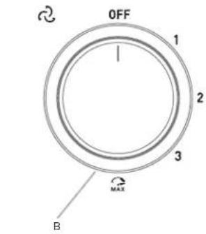
text_image
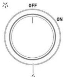
OFF 1 2 3 MAX BA. Lamps knob
B. Blower knob
Operating the lamps
- Turn the light switch to the "ON" position to turn the range hood lights On.
- Turn the light switch to the "OFF" position to turn the range hood lights Off.
Operating the blower
- Turn the blower switch at "1" to turn the range hood on.
- Turn the blower switch to the desired speed position.
- Turn the blower switch to the "MAX" position to turn the range hood on High.
- Turn the blower switch to the "OFF" position to turn the range hood blower Off.
Auto On blower
The range hood is equipped with a sensor to automatically turn on the blower when excessive heat is detected in the control area. When the blower switch is in the "Off" position, this sensor will turn the blower to high speed when necessary. When the heat decreases, the blower will turn off. When the blower switch is in the On position, the heat sensor is not active and the range hood functions normally.
Maintenance
Cleaning
Exterior surfaces:
To avoid damage to the exterior surface, do not use steel wool or soap-filled scouring pads. Rub in direction of the grain line to avoid scratching the surface. Always wipe dry to avoid water marks.
• Stainless Steel Cleaner and Polish.
- Mild liquid detergent and water.
- Wipe with damp soft cloth or non abrasive sponge, then rinse with clean water and wipe dry.
- Do not use chlorine base cleaners.
Metal Filters and Drip Trays:
- Use 2 hands to remove filters.
- Grasp filter handles, pull toward the front of range hood and pull down on the rear handle to remove. Repeat for each filter.
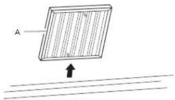
text_image
AA. Grease filter
- Remove grease drip tray.
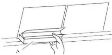
natural_image
Line drawing of a hand holding a rectangular object on a horizontal surface, with no text or symbols present.A. Drip tray
- Wash metal filters and grease trays as needed in dishwasher or hot detergent solution to clean.
- Replace grease drip tray.
- Reinstall filters, grasp filter handles and place front edge of filter into the hood.
- Push up on the back handle and set rear of filter into the drip tray to secure. Repeat for each filter.
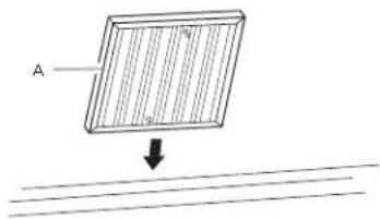
text_image
AA. Grease filter
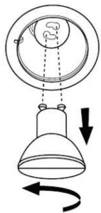
Replacing a LED Lamp
Turn off the range hood and allow the LED lamp to cool. To avoid damage or decreasing the life of the new lamp, do not touch lamp with bare fingers. Replace lamp, using tissue or wearing cotton gloves to handle lamp. If new lamps do not operate, make sure the lamps are inserted correctly before calling service.
1 Disconnect power.
2 Push up on the lens and turn it counterclockwise.
3 Remove the lamp and replace it with a 120-volt, 7.5 W watt maximum halogen lamp with a GU10 base. Turn it clockwise to lock it into place.
4 Repeat steps 2-3 for the other lamps if needed.
5 Reconnect power.
text_image
Diagram showing a lamp with a hanging ring and directional arrows indicating rotation or motion.TO OBTAIN SERVICE UNDER WARRANTY
Owner must present proof of original purchase date. Please keep a copy of your dated proof of purchase (sales slip) in order to obtain service under warranty.
PARTS AND SERVICE WARRANTY
For the period of two (2) years from the date of the original purchase, Elica will provide free of charge, non consumable parts or components that failed due to manufacturing defects. During these two (2) years limited warranty, Elica will also provide free of charge, all labor and in-home service to replace any defective parts.
WHAT IS NOT COVERED
• Damage or failure to the product caused by accident or act of God, such as, flood, fire or earthquake.
- Damage or failure caused by modification of the product or use of non-genuine parts.
- Damage or failure to the product caused during delivery, handling or installation.
- Damage or failure to the product caused by operator abuse.
• Damage or failure to the product caused by dwelling fuse replacement or resetting of circuit breakers.
- Damage or failure caused by use of product in a commercial application.
• Service trips to dwelling to provide use or installation guidance.
• Light bulbs, metal or carbon filters and any other consumable part.
• Normal wear of finish.
- Wear to finish due to operator abuse, improper maintenance, use of corrosive or abrasive cleaning products/pads and oven cleaner products.
WHO IS COVERED
This warranty is extended to the original purchaser for products purchased for ordinary residential use in North America (Including the United States, Guam, Puerto Rico, US Virgin Islands & Canada).
This warranty is non-transferable and applies only to the original purchaser and does not extend to subsequent owners of the product. This warranty is made expressly in lieu of all other warranties, expressed or implied, including, but not limited to any implied warranty of merchantability or fitness for a particular purpose and all other obligations on the part of Elica North America, provided, however, that if the disclaimer of implied warranties is ineffective under applicable law, the duration of any implied warranty arising by operation of law shall be limited to two (2) years from the date of original purchase at retail or such longer period as may be required by applicable law.
This warranty does not cover any special, incidental and/or consequential damages, nor loss of profits, suffered by the original purchaser, its customers and/or the users of the Products.
WHO TO CONTACT
To obtain service under warranty or for any service related question:
• Elica North America Service, call at 1 888 732 8018
- For Eastern Canada, call AGI Services at 1888 651 2534 Ask for the service department
• elica@servicepower.com
FRANÇAIS
Table des matières
DIMENSIONS DU PRODUIT
text_image
F I J G E D H C A B JModèles
| EAR628S4 | ETR134S1 | EAR134S4 | EAR140S4 | EAR146S4 | |
| A | 28 12 " (72.4 cm) | 34 12 " (87.6 cm) | 40 12 " (103 cm) | 46 12 " (118 cm) | |
| B | 22" (55.9 cm) | 18" (45.7 cm) | 22" (55.9 cm) | ||
| C 5 | 716 " (13.8 cm) | ||||
| D 6 | 12 " (16.4 cm) | ||||
| E 27 | 916 " (70 cm) | ||||
| F 12 | 716 " (31.6 cm) | ||||
| G 29 | 916 " (75.7 cm) | ||||
| H 10 | 18 " (25.7 cm) | ||||
| I 10" (25.4 cm) | |||||
| J | 74 " (1.9 cm) | ||||
LISTE DES PIÈCES
Prepare the Location
text_image
Technical diagram of a mechanical component with numbered parts and internal featuresnatural_image
Illustration of hands holding circular components with a black arrow indicating direction (no text or symbols)natural_image
Diagram showing a black arrow pointing to circular features on a textured surface with diagonal lines (no text or symbols)Commandes
text_image
OFF ON A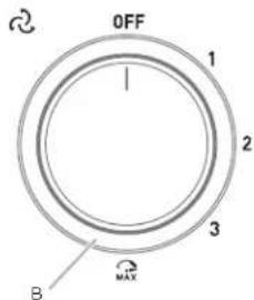
text_image
OFF 1 2 3 B MAXnatural_image
Simple line drawing of a hand pressing down on a rectangular object (no text or symbols)text_image
Diagram showing a lamp with a circular head and a hanging lamp, illustrating the concept of light or brightness.POUR OBTENIR UN DEPANNAGE SOUS GARANTIE
DIMENSIONES DEL PRODUCTO
text_image
F I J G E D H C A B J| Modelos | |||||
| EAR628S4 | ETR134S1 | EAR134S4 | EAR140S4 | EAR146S4 | |
| A | 2812" (72.4 cm) | 3412" (87.6 cm) | 4012" (103 cm) | 4612" (118 cm) | |
| B | 22" (55.9 cm) | 18" (45.7 cm) | 22" (55.9 cm) | ||
| C 5 | 716" (13.8 cm) | ||||
| D 6 | 12" (16.4 cm) | ||||
| E 27 | 916" (70 cm) | ||||
| F 12 | 716" (31.6 cm) | ||||
| G 29 | 1316" (75.7 cm) | ||||
| H 10 | 18" (25.7 cm) | ||||
| I | 10" (25.4 cm) | ||||
| J | 34" (1.9 cm) | ||||
LISTA DE MATERIALES
text_image
Technical diagram of a mechanical component with numbered parts and internal featuresnatural_image
Illustration of hands adjusting a mechanical component with a black arrow indicating motion (no text or symbols)natural_image
Diagram showing a black arrow pointing to circular features on a textured surface with diagonal lines and small dots (no text or symbols)Controles
text_image
OFF ON A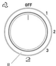
text_image
OFF 1 2 3 B MAXnatural_image
Simple line drawing of a rectangular object with horizontal lines and an arrow pointing upward, no text or symbols present.A. Filtro de grasa
natural_image
Simple line drawing of a hand holding a rectangular object on a surface, with no text or symbols present.A. Grasera