557 - Drill Porter-Cable - Free user manual and instructions
Find the device manual for free 557 Porter-Cable in PDF.
| Product Type | Lamello Biscuit Jointer (biscuit joint assembly) |
| Brand | Porter-Cable |
| Model | 557 |
| Power Supply | 120 V AC, 60 Hz |
| Rated Current | 6 A (estimated) |
| Maximum Cutting Depth | 101.6 mm (4 in) with 4 in blade |
| Compatible Blades | 101.6 mm (4 in) and 50.8 mm (2 in) |
| Cutting Angles | 0° to 135°, adjustable stop at 90° |
| Supported Biscuit Sizes | FF, 0, 10, 20, Duplex, Simplex, #6 |
| Adjustable Fence | Yes, with micro-adjustment of height and angle |
| Double Insulation | Yes (Class II) |
| Estimated Weight | Approximately 3.6 kg |
| Noise Level | Hearing protection recommended |
| Dust Extraction System | Vacuum port (25.4 mm), dust bag included |
| Included Accessories | Dust bag, deflector, alignment plate, hex key |
| Maintenance | Clean with compressed air, lubrication not required, inspect brushes after 100 h |
| Warranty | 3-year limited + 1 year free maintenance + 90 days satisfaction guarantee |
| Repairability | Identical spare parts, repair by Porter-Cable authorized center |
Frequently Asked Questions - 557 Porter-Cable
User questions about 557 Porter-Cable
0 question about this device. Answer the ones you know or ask your own.
Ask a new question about this device
Download the instructions for your Drill in PDF format for free! Find your manual 557 - Porter-Cable and take your electronic device back in hand. On this page are published all the documents necessary for the use of your device. 557 by Porter-Cable.
USER MANUAL 557 Porter-Cable
TROUBLESHOOTING....17
MAINTENANCE 17
SERVICE....18
ACCESSORIES....18
THREE YEAR LIMITED WARRANTY 18
WARNING LABEL REPLACEMENT 19
FRANÇAIS. 20
ESPAÑOL 40
DEFINITIONS - SAFETY GUIDELINES
▲DANGER: indicates an imminently hazardous situation which, if not avoided, will result in death or serious injury.
⚠ WARNING: indicates a potentially hazardous situation which, if not avoided, could result in death or serious injury.
▲CAUTION: indicates a potentially haz ard ous situation which, if not avoided may result in minor or moderate injury.
NOTICE: used without the safety alert symbol indicates potentially hazardous situation which, if not avoided, may result in property damage.

A WARNING:
injury, read the instruction manual.
GENERAL POWER TOOL SAFETY WARNINGS
WARNING:
Read all safety warnings and all instructions Failure to follow the warnings and instructions may result in electric shock, fire and/or serious injury.
SAVE ALL WARNINGS AND INSTRUCTIONS FOR FUTURE REFERENCE
The term “power tool” in the warnings refers to your mains-operated (corded) power tool or battery-operated (cordless) power tool.
1) WORK AREA SAFETY
a) Keep work area clean and well lit. Cluttered or dark areas invite accidents.
b) Do not operate power tools in explosive atmospheres, such as in the presence of flammable liquids, gases or dust. Power tools create sparks which may ignite the dust or fumes.
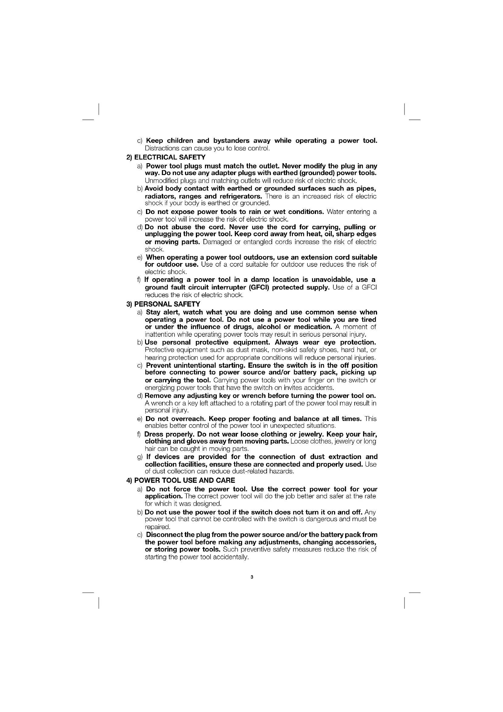
c) Keep children and bystanders away while operating a power tool. Distractions can cause you to lose control.
2) ELECTRICAL SAFETY
a) Power tool plugs must match the outlet. Never modify the plug in any way. Do not use any adapter plugs with earthed (grounded) power tools. Unmodified plugs and matching outlets will reduce risk of electric shock.
b) Avoid body contact with earthed or grounded surfaces such as pipes, radiators, ranges and refrigerators. There is an increased risk of electric shock if your body is earthed or grounded.
c) Do not expose power tools to rain or wet conditions. Water entering a power tool will increase the risk of electric shock.
d) Do not abuse the cord. Never use the cord for carrying, pulling or unplugging the power tool. Keep cord away from heat, oil, sharp edges or moving parts. Damaged or entangled cords increase the risk of electric shock.
e) When operating a power tool outdoors, use an extension cord suitable for outdoor use. Use of a cord suitable for outdoor use reduces the risk of electric shock.
f) If operating a power tool in a damp location is unavoidable, use a ground fault circuit interrupter (GFCI) protected supply. Use of a GFCI reduces the risk of electric shock.
3) PERSONAL SAFETY
a) Stay alert, watch what you are doing and use common sense when operating a power tool. Do not use a power tool while you are tired or under the influence of drugs, alcohol or medication. A moment of inattention while operating power tools may result in serious personal injury.
b) Use personal protective equipment. Always wear eye protection. Protective equipment such as dust mask, non-skid safety shoes, hard hat, or hearing protection used for appropriate conditions will reduce personal injuries.
c) Prevent unintentional starting. Ensure the switch is in the off position before connecting to power source and/or battery pack, picking up or carrying the tool. Carrying power tools with your finger on the switch or energizing power tools that have the switch on invites accidents.
d) Remove any adjusting key or wrench before turning the power tool on. A wrench or a key left attached to a rotating part of the power tool may result in personal injury.
e) Do not overreach. Keep proper footing and balance at all times. This enables better control of the power tool in unexpected situations.
f) Dress properly. Do not wear loose clothing or jewelry. Keep your hair, clothing and gloves away from moving parts. Loose clothes, jewelry or long hair can be caught in moving parts.
g) If devices are provided for the connection of dust extraction and collection facilities, ensure these are connected and properly used. Use of dust collection can reduce dust-related hazards.
4) POWER TOOL USE AND CARE
a) Do not force the power tool. Use the correct power tool for your application. The correct power tool will do the job better and safer at the rate for which it was designed.
b) Do not use the power tool if the switch does not turn it on and off. Any power tool that cannot be controlled with the switch is dangerous and must be repaired.
c) Disconnect the plug from the power source and/or the battery pack from the power tool before making any adjustments, changing accessories, or storing power tools. Such preventive safety measures reduce the risk of starting the power tool accidentally.
d) Store idle power tools out of the reach of children and do not allow persons unfamiliar with the power tool or these instructions to operate the power tool. Power tools are dangerous in the hands of untrained users.
e) Maintain power tools. Check for misalignment or binding of moving parts, breakage of parts and any other condition that may affect the power tool's operation. If damaged, have the power tool repaired before use. Many accidents are caused by poorly maintained power tools.
f) Keep cutting tools sharp and clean. Properly maintained cutting tools with sharp cutting edges are less likely to bind and are easier to control.
g) Use the power tool, accessories and tool bits, etc. in accordance with these instructions, taking into account the working conditions and the work to be performed. Use of the power tool for operations different from those intended could result in a hazardous situation.
5) SERVICE
a) Have your power tool serviced by a qualified repair person using only identical replacement parts. This will ensure that the safety of the power tool is maintained.
ADDITIONAL SPECIFIC SAFETY RULES
- Wait for the cutter to stop before setting the tool down. An exposed rotating cutter may engage the surface leading to possible loss of control and serious injury.
- Hold the power tool by insulated gripping surfaces only, because the cutter may contact its own cord. Cutting a "live" wire may make exposed metal parts of the power tool "live" and could give the operator an electric shock.
- Use clamps or another practical way to secure and support the workpiece to a stable platform. Holding the work by your hand or against the body leaves it unstable and may lead to loss of control.
- ▲WARNING: Keep hands away from cutting area. Keep hands away from blade. Do not reach underneath work while blade is rotating.
- CAUTION: If tool is dropped, guard may distort restricting operation. Keep slide mechanism free of wood chips. Occasionally lubricate with light tool oil. DO NOT OVER LUBRICATE as this creates excessive sawdust buildup.
- Blades must be rated for at least the speed marked on the tool. Blades running over rated speed can fly apart and cause injury.
- Always use the guard. The guard protects the operator from broken blade fragments and unintentional contact with the blade.
- Do not use blunt or damaged blades. Personal injury may occur.
- Keep blades sharp. Sharp blades will do the job better and safer.
- When you have finished a cut be careful not to come into contact with the blade. Turn off the motor immediately.
- Never hold work in or with your hand, lap, or against other parts of your body.
- Keep guards in working order. Check operation before each use. Do not use if guard does not close briskly over blade.
- Avoid cutting nails and knots. Inspect for and remove all nails from lumber before cutting. Try to layout cuts between knots.
- Laceration hazard. Never remove the return springs. If the springs are removed the tool cannot be operated safely because the blade will not retract following a cut.
- Air vents often cover moving parts and should be avoided. Loose clothes, jewelry or long hair can be caught in moving parts.
- An extension cord must have adequate wire size (AWG or American Wire Gauge) for safety. The smaller the gauge number of the wire, the greater the capacity of the cable, that is 16 gauge has more capacity than 18 gauge. An undersized cord will cause a drop in line voltage resulting in loss of power and overheating. When using more than one extension to make up the total length, be sure each individual extension contains at least the minimum wire size. The following table shows the correct size to use depending on cord length and nameplate ampere rating. If in doubt, use the next heavier gauge. The smaller the gauge number, the heavier the cord.
| Minimum Gauge for Cord Sets | ||||||
| Ampere Rating | Volts Total Length of Cord in Feet (meters) | |||||
| 120V 25 (7.6) 50 (15.2) 100 (30.5) 150 (45.7) | ||||||
| 240V 50 (15.2) 100 (30.5) 200 (61.0) 300 (91.4) | ||||||
| More Than | Not More Than | AWG | ||||
| 0 6 18 | 16 16 14 | |||||
| 6 | 10 | 18 | 16 | 14 | 12 | |
| 10 | 12 | 16 16 14 12 | ||||
| 12 | 16 | 14 12 | Not Recommended | |||
⚠ WARNING: ALWAYS use safety glasses. Everyday eyeglasses are NOT safety glasses. Also use face or dust mask if cutting operation is dusty. ALWAYS WEAR CERTIFIED SAFETY EQUIPMENT:
• ANSI Z87.1 eye protection (CAN/CSA Z94.3),
• ANSI S12.6 (S3.19) hearing protection,
• NIOSH/OSHA/MSHA respiratory protection.
⚠ WARNING: Some dust created by power sanding, sawing, grinding, drilling, and other construction activities contains chemicals known to the State of California to cause cancer, birth defects or other reproductive harm. Some examples of these chemicals are:
- lead from lead-based paints,
• crystalline silica from bricks and cement and other masonry products, and
• arsenic and chromium from chemically-treated lumber.
Your risk from these exposures varies, depending on how often you do this type of work. To reduce your exposure to these chemicals: work in a well ventilated area, and work with approved safety equipment, such as those dust masks that are specially designed to filter out microscopic particles.
- Avoid prolonged contact with dust from power sanding, sawing, grinding, drilling, and other construction activities. Wear protective clothing and wash exposed areas with soap and water. Allowing dust to get into your mouth, eyes, or lay on the skin may promote absorption of harmful chemicals.
⚠ WARNING: Use of this tool can generate and/or disperse dust, which may cause serious and permanent respiratory or other injury. Always use NIOSH/OSHA approved respiratory protection appropriate for the dust exposure. Direct particles away from face and body.
WARNING: Always wear proper personal hearing protection that conforms to ANSI S12.6 (S3.19) during use. Under some conditions and duration of use, noise from this product may contribute to hearing loss.
- The label on your tool may include the following symbols. The symbols and their definitions are as follows:
V....volts
A.....amperes
Hz......hertz
W ......watts
min ......minutes or AC ......alternating
or DC .....direct current current
Class I Construction or AC/DC ...alternating or
(grounded) direct
☐......ClassIIConstruction no......no load
(double insulated) speed
.../min ....../per minute n ....../rated
BPM ....beats per minute ♡ ....earthing
IPM ....impacts per minute terminal
RPM ....revolutions per minute ⚠️ ....safety alert symbol
sfpm ....surface feet per minute
current
speed
SAVE THESE INSTRUCTIONS
MOTOR
Be sure your power supply agrees with nameplate marking. 120 Volts AC means your tool will operate on alternating or direct current. As little as 10% lower voltage can cause loss of power and can result in overheating. All PORTER-CABLE tools are factory-tested; if this tool does not operate, check the power supply.
⚠ WARNING: Accessories must be rated for at least the speed recommended on the tool warning label. Accessories running over rated speed can fly apart and cause injury. Accessory ratings must always be above tool speed as shown on tool nameplate.
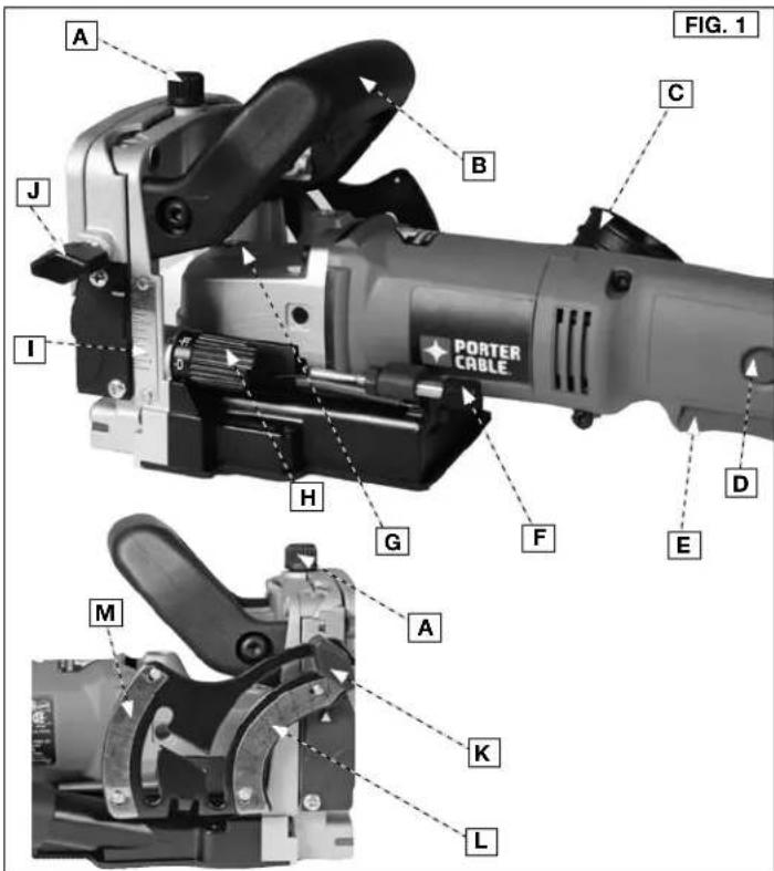
COMPONENTS (FIG. 1)
WARNING: Never modify the power tool or any part of it. Damage or personal injury could result.
A. Fence adjustment knob H. Depth adjustment turret
B. Auxiliary handle I. Depth scale
C. Dust bag deflector nozzle J. Fence locking knob
D. Lock button K. Scale locking knob
E. Trigger switch L. Lower scale
F. Fine adjustment knob M. Upper scale
G. Spindle lock
INTENDED USE
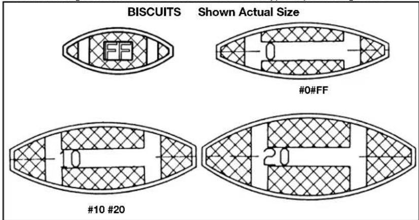
Model 557 plate joiner is designed to cut the grooves required for PORTER-CABLE biscuit sizes "FF", "0", "10", and "20". Adjustments are also provided which allow the tool to cut grooves for #6 biscuits, Duplex accessories and Simplex accessories sold by other manufacturers.
DO NOT use under wet conditions or in presence of flammable liquids or gases.
The 557 plate joiner is a professional power tool. DO NOT let children come into contact with the tool. Supervision is required when inexperienced operators use this tool.
text_image
A J I H G F E M A K L PORTER CABLE C FIG. 1 BASSEMBLY
NOTE: This tool is shipped completely assembled. No assembly time or tools are required.
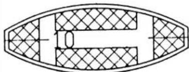
SELECTING THE BISCUIT
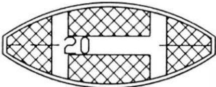
Biscuits are 5/32" (4 mm) thick. They are available from PORTER-CABLE in four sizes. Choose the largest biscuit that will accommodate the type of joint being made.
text_image
BISCUITS Shown Actual Size #0#FF #10 #20 20OPERATION
⚠ WARNING: To reduce the risk of injury, turn unit off and disconnect it from power source before installing and removing accessories, before adjusting or when making repairs. An accidental start-up can cause injury.
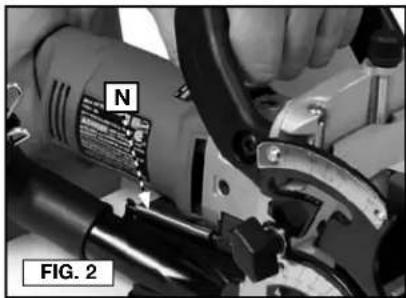
⚠ WARNING: Laceration hazard. Never remove the return springs (N) Fig. 2. If the springs are removed the tool cannot be operated safely because the blade will not retract following a cut.
natural_image
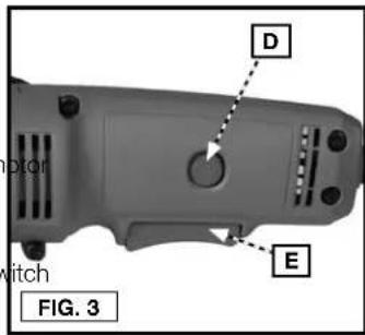
Close-up of a hand operating a mechanical tool with a labeled component (N), no visible text or symbols beyond labelsTO START AND STOP TOOL (FIG. 3)
⚠ WARNING: Make sure switch is OFF and power circuit voltage is the same as that shown on the specification plate.
- Connect tool to power circuit.
- Grip tool firmly to resist starting torque, and squeeze trigger switch (E) to START tool.
- Release trigger switch to STOP tool.
- To lock the trigger switch in the "ON" position:
- Squeeze trigger switch to START m and depress lock button (D), while releasing trigger switch. Release lock button.
• To STOP tool, squeeze trigger sw and release, while leaving lock button free to spring out.
text_image
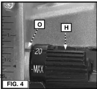
D E motor witch FIG. 3ADJUSTING DEPTH OF GROOVE (FIG. 4)
A "quick set" depth adjusting turret (H), provides for quick changes in depth of cut to accommodate the various sizes of available biscuits and other accessories. To set depth of cut, rotate depth adjusting turret until desired size marking on turret aligns with the index mark (O). The following depth settings are provided:
0 For "0" size accessories
10 For "10" size accessories
20 For "20" size accessories
MAX For "6" size accessories provides maximum depth of cut with 4" (101.6 mm) blade
FF For PORTER-CABLE "FF" biscuits Must use 2" (50.8 mm) blade
D For "Duplex" accessories
S For "Simplex" accessories
text_image
O H -20 -MAX FIG. 4FINE ADJUSTMENT (FIG. 5)
The "quick set" depth adjustment is adjusted at the factory to produce joints with nominal clearance (biscuit to groove). A fine adjustment is provided allowing you to reduce or increase the clearance as desired. To adjust:
- Use an 7/16" wrench to loosen locknut (P).
- Rotate fine adjustment knob (F), to desired position (rotate knob clockwise to reduce depth of cut, rotate knob counter-clockwise to increase depth of cut).
- While holding adjustment knob in desired position, tighten locknut firmly.
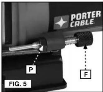
text_image
PORTER CABLE P F FIG. 5ADJUSTABLE FENCE
Model 557 is equipped with an integral, adjustable fence which:
- provides micro-height adjustment. The distance scale includes indexes to top of cut, to center of cut, and to bottom of cut.
- tilts 0^ through 135^ , with an adjustable stop at 90^ .
- does not have to be removed to make "flush" cuts.
HEIGHT ADJUSTMENT (FIG. 6, 7)
- Loosen locking knob (J), and rotate knob (A) to position the fence as desired, (rotate knob clockwise to raise fence, rotate knob counterclockwise to lower fence).
- The depth scale (l), indicates the distance from the top edge of the workpiece to the blade: NOTE: The bottom line on scale (l) begins at 1/4" (6.4 mm) and all lines are in 1/16" (1.6 mm) increments.
• The line across the center of the index block (Q) indicates the distance to the center of the blade.
• The top edge of the index block (Q) indicates the distance to the bottom of the blade.
• The bottom edge of the index block (Q) indicates the distance to the top of the blade.
- The width of the index block (Q) is equal to the thickness of the blade. 3. Once fence is in desired position, tighten knob (J).
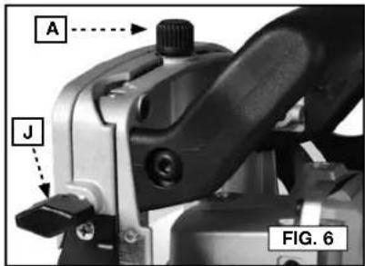
text_image
A J FIG. 6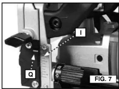
text_image
I Q FIG. 7ANGLE ADJUSTMENT (FIG. 8-11)
- Loosen locking knob (K).
- For angles between 0^ and 90^ - swing fence downward until desired angle on lower scale (L), aligns with lower index mark (S). Tighten knob (K), to secure in place.
- For angles between 90° and 135° - swing fence downward until the "gate" between the upper scale (M), and lower scale (L), aligns with locking knob. Swing scale arm down to align knob with upper scale. Move fence until desired angle on upper scale (M), aligns with upper index mark (R). Tighten knob (K), to secure in place.

text_image
0 DEGREES R T K L S FIG. 8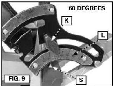
text_image
60 DEGREES K L S FIG. 9
text_image
90 DEGREES M R K S FIG. 10
text_image
135 DEGREES R M K S FIG. 11FINE ADJUSTMENT (90° POSITION)
The adjustable 90° stop is factory adjusted for 90° and should not require additional adjustment. If "fine tuning" of the stop position is required: use a 5/64" hex wrench (not furnished), to rotate set-screw (T) Fig. 8. Rotate the set-screw clockwise to reduce the angle of the fence, rotate the set-screw counter-clockwise to increase the angle of the fence.
BLADE REPLACEMENT
⚠ WARNING: To reduce the risk of injury, turn unit off and disconnect it from power source before installing and removing accessories, before adjusting or when making repairs. An accidental start-up can cause injury.
WARNING: Handle blades carefully. They are extremely sharp.
NOTE: Model 557 is shipped with a 4" (101.6 mm) diameter blade installed. This blade is used for all operations except for the "FF" biscuit. The 2" (50.8 mm) blade is sold separately at additional cost from an authorized service center.
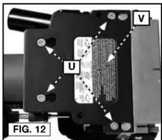
TO REMOVE 4" (101.6 MM) BLADE (FIG. 12-15)
- Turn off and unplug the plate joiner.
-
Loosen the four screws (U) from the bottom of the blade cover (V) and then slide and lift the blade cover from the unit.
-
Depress and hold the spindle lock pin (G) on the top of the gear case while rotating the blade by hand until the spindle lock engages.
-
Continue to depress the spindle lock pin (G) while loosening (counterclockwise) the blade retaining screw (X) using the hex wrench provided.
text_image
U V FIG. 12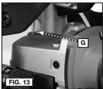
text_image
G FIG. 13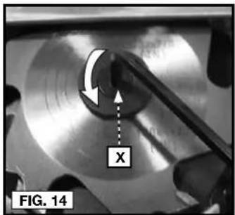
text_image
FIG. 14 X-
Remove the blade.
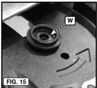
-
Before installing new blade ensure clamp washer (W) is installed as shown in Figure 15 and blade teeth are pointed in the direction of the rotation arrow as shown in Figure 16. Reinstall the blade by reversing the steps 2–4.
IMPORTANT: Always check the fine depth adjustment when replacing the blade. Adjust if necessary. (See Fine Adjustment section).
text_image
W FIG. 15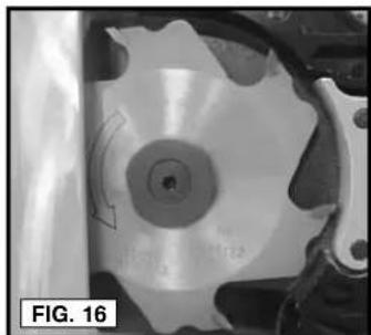
natural_image
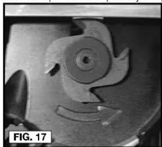
Close-up of a mechanical component with a circular feature and curved arrow, labeled 'FIG. 16' (no readable text or symbols)TO USE 2" (50.8 MM) BLADE (FIG. 12-15, 17-21)
-
Turn off and unplug the plate joiner.
-
Loosen the four screws (U) from the bottom of the blade cover (V) and then slide and lift the blade cover from the unit. (Fig. 12)
-
Depress and hold the spindle lock pin (G) on the top of the gear case while rotating the blade by hand until the spindle lock engages. (Fig. 13)
-
Continue to depress the spindle lock pin (G) while loosening (counterclockwise) the blade retaining screw (X) using the hex wrench provided. (Fig. 14)
-
Remove the 4" (101.6 mm) blade and store for future use.
-
Before installing new blade ensure clamp washer (W) is installed as shown in Figure 15 and blade teeth are pointed in the direction of the rotation arrow as shown in Figure 17. Place the 2" (50.8 mm) blade onto the clamp washer (W). Reinstall the blade by reversing the steps 2–4.
-
Rotate the "quick set" depth adjusting turret (H) to the "FF" position.
natural_image
Close-up of a mechanical component with a circular feature and curved edge, labeled 'FIG. 17' (no readable text or symbols beyond label)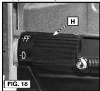
text_image
H FF D FIG. 18- Place the tool on a bench in the vertical position.
⚠ WARNING: Risk of personally injury. Blade will be exposed.
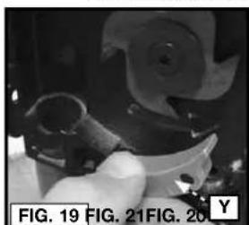
a. Pull safety lever (Y) straight out as shown in Figure 19.
b. Press the plunge mechanism (Z) down fully, rotate and reposition the safety lever (Y) into the hole (AA) as shown in Figure 20 and 21. Slowly release pressure on the plunge mechanism.
natural_image
Close-up of a hand using a tool to adjust or install a mechanical component (no visible text or symbols)
text_image
Z AA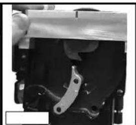
natural_image
Close-up of a mechanical component with a metallic bracket and mounting base (no visible text or symbols)- Reposition and slide the blade cover (V) onto the tool and secure in place with the four retaining screws (U).
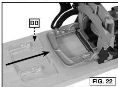
ALIGNMENT PLATE (For Narrow Stock) (FIG. 22-23)
When joining narrow material, install the alignment plate (BB) Fig. 22 (furnished with tool). The alignment plate provides added support for narrow material, and has index marks to aid in centering the cut in the narrow material. Index marks are provided for 1-1/2" (38.1 mm) wide, and 2" (50.8 mm) wide material.
text_image
BB FIG. 22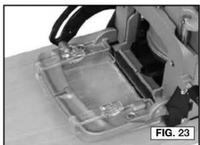
natural_image
Close-up of a mechanical device with transparent casing and internal components (no visible text or symbols)12
To install alignment plate:
-
Align alignment plate (BB) with fence (see Fig. 22).
-
Slide alignment plate onto fence until it is seated (see Fig. 23).
NOTE: When alignment plate is installed, increase tool depth setting by 5/32" (4.0 mm) (to allow for thickness of the alignment plate).
- To remove alignment plate, lift lightly on the alignment plate and slide off fence.
"DOUBLE" BISCUITS
The alignment plate may also be used as a spacer to produce a groove that is wide enough to accept two biscuits. After cutting a groove (or a group of grooves) in the normal fashion, install the alignment plate and repeat the cuts. This will double the width of each groove so that two biscuits can be installed in each groove.
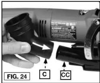
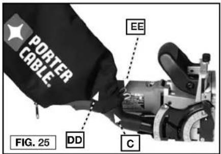
DUST PORT (FIG. 24-25)
The tool is equipped with a dust port (CC) Fig. 24. A large volume of sawdust and chips will be exhausted from this port during tool operation. A dust bag (DD) Fig. 25 and a dust/chip deflector nozzle (C) Fig. 24 are furnished. A standard 1" (25.4 mm) vacuum hose can be connected to the dust port to facilitate dust collection.
⚠ CAUTION: Do not operate the tool without a dust/chip deflector nozzle and dust bag, or a vacuum hose, attached to the dust port.
text_image
FIG. 24 C CCDUST/CHIP DEFLECTOR NOZZLE (FIG. 24)
The dust/chip deflector nozzle (C) pushes onto the dust port (CC) Fig. 24.
ATTACHING DUST BAG (FIG. 25)
Depress spring clips (EE) Fig. 25 and clip dust bag (DD) on end of dust/chip deflector (C). The bag is equipped with a zipper for ease emptying of the collected material.
text_image
PORTER CABLE. EE FIG. 25 DD C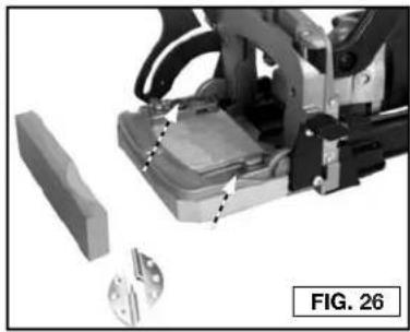
natural_image
Mechanical assembly with robotic arm and mechanical components, no visible text or symbols"DUPLEX" HINGES (FIG. 26)
You can use the 557 to make the mortises required for installing "duplex" hinges. Make a spacer and attach it to the 557 fence. The spacer can be made of scrap 3/4" (19 mm) wood. Cut the spacer to approximately 3-3/8" by 5-1/4" (85.7 mm by 133.4 mm) and attach it to the holes in the fence with two 3/4" (19 mm) wood screws.
#6 BISCUITS
With the 4" (101.6 mm) blade installed, set the depth adjusting turret to the MAX position. Two cuts will be required to produce each groove for a #6 biscuit. Space the centerlines of these two cuts 1/4" (6.4 mm) apart. When laying-out these cuts, mark the first cut centerline, move over 1/4" (6.4 mm and mark the second cut centerline.
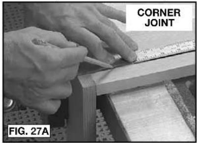
POSITIONING GROOVES
The number of grooves (biscuits) used in a joint may be varied to provide the strength required for the particular application. Typically position the center of the first groove approximately 2" (50.8 mm) from the edge of the work with additional grooves spaced at 3" to 6" (76.2 mm to 152.4 mm) on centers.
text_image
CORNER JOINT FIG. 27A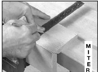
natural_image
Close-up of hands using a metal tool to cut or work on wooden blocks (no visible text or symbols)
text_image
SURFACE JOINT FIG. 27B FIG. 27C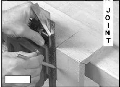
natural_image
Close-up of hands using a tool to cut or trim wood, no visible text or symbolsIn most cases use one line of grooves (biscuits) positioned approximately along the centerline of the material. On thicker material use an additional row(s) of biscuits for added strength.
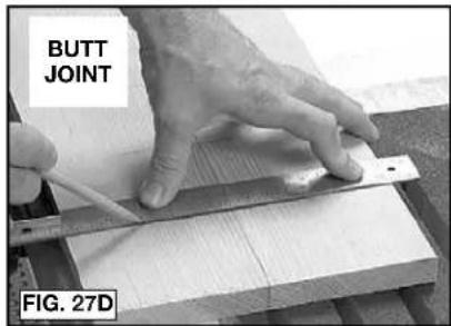
Position the two workpieces (to be joined) in the relationship desired after joining. Mark the centerline of each groove required as shown in Fig. 27A–D. Use a square to assure accuracy.
text_image
BUTT JOINT FIG. 27DPRACTICE CUTS
After each set-up or adjustment to the tool make several practice cuts in scrap material.
CORNER JOINTS
- Layout groove positions as described in Positioning Grooves section.
- Set depth stop turret to desired biscuit (or other accessory) size.
- Set the tilt fence to the 90° position (see Angle Adjustment section).
- Set fence height adjustment to desired height (usually half the material thickness), (see Height Adjustment section.)
-
Clamp the workpiece securely.
-
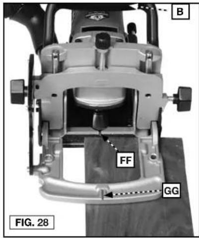
Position tool to workpiece with the bottom of fence resting on workpiece. Align guide notch (FF) or (GG) Fig. 28 with a groove centerline. Apply pressure to auxiliary handle (B) Fig. 28, to keep front of tool and fence in firm contact with workpiece.
-
Hold tool firmly as shown in Fig. 29. Squeeze trigger switch to start tool.
text_image
B FF GG FIG. 28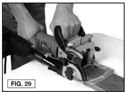
natural_image
Person using a power saw on a cutting board, no visible text or symbols-
At a slow, steady pace, push tool forward in base as far as depth stop allows.
-
Release trigger switch to stop tool and remove tool from work.
-
Repeat steps 6 through 9 until all the grooves for this joint are completed.
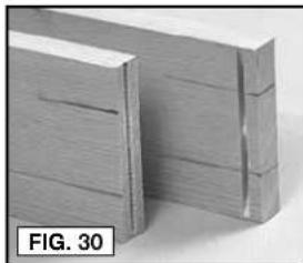
NOTE: Assemble all joints and verify alignments before applying glue (see Fig. 30).
natural_image
Close-up of two wooden blocks with visible grain patterns, labeled 'FIG. 30' (no other text or symbols)
natural_image
Close-up of stacked wooden blocks with visible grain patterns (no text or symbols)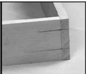
natural_image
Close-up of a wooden plank with visible grain and texture (no text or symbols)SURFACE ("T") JOINTS
- Layout groove positions as described in Positioning Grooves section.
- Set depth stop turret to desired biscuit (or other accessory), size.
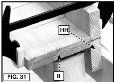
- Mark centerline of joint on workpiece (HH) (see Fig. 31).
text_image
HH II FIG. 31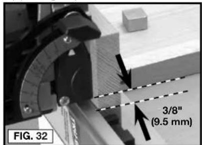
text_image
FIG. 32 3/8" (9.5 mm)- Clamp a straight edge guide to the workpiece 3/8" (9.5 mm) back from the joint centerline (as marked in Step 2). Clamp workpiece securely (see Fig. 32).
- Set tilt fence to 0^ position (see Angle Adjustment Section section).
- Position tool to workpiece with bottom of base against straight edge and guide notch (FF) Fig. 33, aligned with a groove centerline. Apply pressure to auxiliary handle (B) Fig. 33 to hold tool firmly in place.
FF
B
FIG. 33
FIG. 34
- Hold tool firmly as shown in Fig. 29. Squeeze trigger switch to start tool.
- At a slow, steady pace, push tool forward in base as far as depth stop allows.
- Release trigger switch to stop tool and remove tool from work.
- Repeat steps 5 through 8 until all the grooves in workpiece (HH) are completed.
- Follow steps 3 through 10 of Corner Joints section to complete required grooves in workpiece (II) Fig. 31.
NOTE: Assemble all joints and verify alignments before applying glue (see Fig. 33).
BUTT JOINTS
Tool adjustment and operation for producing butt joints (see Fig. 27D) are the same as for Corner Joints.
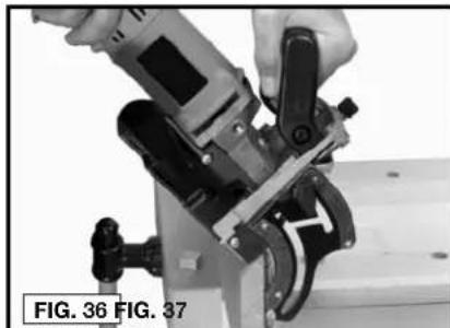
MITER JOINTS (FIG. 35–37)
- Layout groove positions as described in Positioning Grooves section.
B
-
Set depth adjustment turret to desired biscuit (or other accessory) size.
-
Set the tilt fence to desired angle (see Angle Adjustment section).
-
Set fence height adjustment to desired height (see Height Adjustment section).
-
Clamp workpiece securely.
-
Position tool to workpiece utilizing either guide notch (FF) or (GG) to align tool with a groove centerline. Apply pressure to auxiliary handle (B) to hold tool firmly in place.
FF
- Hold tool firmly as shown in Figure 36, and squeeze trigger switch to start tool.
GG
-
At a slow, steady pace, push tool forward in base as far as depth stop allows.
-
Release trigger switch to stop tool and remove tool from work.
-
Repeat Steps 6 through 8 until all the grooves for this joint are completed.
NOTE: Assemble all joints and verify alignments before applying glue (see Fig. 37).
natural_image
Close-up of a hand using a power tool to adjust or install a mechanical component (no visible text or symbols)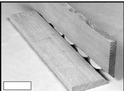
natural_image
Close-up of two wooden planks with visible grain and a central slot, no text or symbols presentTROUBLESHOOTING
For assistance with your tool, visit our website at www.portercable.com for a list of service centers, or call the PORTER-CABLE Customer Care Center at (888) 848-5175.
MAINTENANCE
⚠ WARNING: To reduce the risk of injury, turn unit off and disconnect it from power source before installing and removing accessories, before adjusting or when making repairs. An accidental start-up can cause injury.
CLEANING
⚠ WARNING: Periodically blowing dust and chips out of the motor housing using clean, dry compressed air is a suggested maintenance procedure. To reduce the risk of serious personal injury, ALWAYS wear ANSI Z87.1 safety glasses while using compressed air.
⚠ WARNING: When cleaning, use only mild soap and a damp cloth on plastic parts. Many household cleaners contain chemicals which could seriously damage plastic. Also, do not use gasoline, turpentine, lacquer, paint thinner, dry cleaning fluids or similar products which may seriously damage plastic parts. NEVER let any liquid get inside the tool; NEVER immerse any part of the tool into a liquid.
FAILURE TO START
Should your tool fail to start, check to make sure the prongs on the cord plug are making good contact in the outlet. Also, check for blown fuses or open circuit breakers in the line.
LUBRICATION
This tool has been lubricated with a sufficient amount of high grade lubricant for the life of the unit under normal operating conditions. No further lubrication is necessary.
BRUSH INSPECTION
For your continued safety and electrical protection, brush inspection and replacement on this tool should ONLY be performed by a PORTER-CABLE FACTORY SERVICE CENTER OR PORTER-CABLE AUTHORIZED WARRANTY SERVICE CENTER.
At approximately 100 hours of use, take or send your tool to your nearest PORTER-CABLE Factory Service center or PORTER-CABLE Authorized Warranty Service Center to be thoroughly cleaned and inspected. Have worn parts replaced and lubricated with fresh lubricant. Have new brushes installed, and test the tool for performance.
Any loss of power before the above maintenance check may indicate the need for immediate servicing of your tool. DO NOT CONTINUE TO OPERATE TOOL UNDER THIS CONDITION. If proper operating voltage is present, return your tool to the service station for immediate service.
SERVICE
REPLACEMENT PARTS
Use only identical replacement parts. For a parts list or to order parts, visit our service website at www.portercable.com. You can also order parts from your nearest PORTER-CABLE Factory Service Center or PORTER-CABLE Authorized Warranty Service Center. Or, you can call our Customer Care Center at (888) 848-5175.
SERVICE AND REPAIRS
All quality tools will eventually require servicing and/or replacement of parts. For information about PORTER-CABLE, its factory service centers or authorized warranty service centers, visit our website at www.portercable.com or call our Customer Care Center at (888) 848-5175. All repairs made by our service centers are fully guaranteed against defective material and workmanship. We cannot guarantee repairs made or attempted by others.
You can also write to us for information at PORTER-CABLE, 4825 Highway 45 North, Jackson, Tennessee 38305 - Attention: Product Service. Be sure to include all of the information shown on the nameplate of your tool (model number, type, serial number, etc.).
ACCESSORIES
WARNING:
Since accessories, other than those offered by PORTER-CABLE, have not been tested with this product, use of such accessories with this tool could be hazardous. To reduce the risk of injury, only PORTER-CABLE recommended accessories should be used with this product.
A complete line of accessories is available from your PORTER-CABLE Factory Service Center or a PORTER-CABLE Authorized Warranty Service Center. Please visit our Web Site www.portercable.com for a catalog or for the name of your nearest supplier.
THREE YEAR LIMITED WARRANTY
PORTER-CABLE will repair, without charge, any defects due to faulty materials or workmanship for three years from the date of purchase. This warranty does not cover part failure due to normal wear or tool abuse. For further detail of warranty coverage and warranty repair information, visit www.portercable.com or call (888) 848-5175. This warranty does not apply to accessories or damage caused where repairs have been made or attempted by others. This warranty gives you specific legal rights and you may have other rights which vary in certain states or provinces.
In addition to the warranty, PORTER-CABLE tools are covered by our:
1 YEAR FREE SERVICE: PORTER-CABLE will maintain the tool and replace worn parts caused by normal use, for free, any time during the first year after purchase.
90 DAY MONEY BACK GUARANTEE: If you are not completely satisfied with the performance of your PORTER-CABLE Power Tool, Laser, or Nailer for any reason, you can return it within 90 days from the date of purchase with a receipt for a full refund – no questions asked.
LATIN AMERICA: This warranty does not apply to products sold in Latin America. For products sold in Latin America, see country specific warranty information contained in the packaging, call the local company or see website for warranty information.
To register your tool for warranty service visit our website at www.portercable.com.
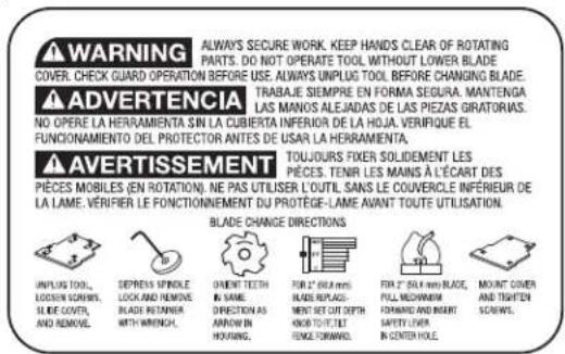
WARNING LABEL REPLACEMENT
If your warning labels become illegible or are missing, call (888) 848-5175 for a free replacement.
text_image
WARNING ALWAYS SECURE WORK. KEEP HANDS CLEAR OF ROTATING PARTS. DO NOT OPERATE TOOL WITHOUT LOWER BLADE COVER. CHECK GUARD OPERATION BEFORE USE. ALWAYS UNPLUG TOOL BEFORE CHANGING BLADE. ADVERTENCIA TRABAJE SEMPRE EN FORMA SEGURA. MANTENDA LAS MANOS ALEJADAS DE LAS PIEZAS GIRATORIAS. NO OPERE LA HERRAMIENTA SIN LA CUBIERTA INFERIOR DE LA HOJA. VERIFIQUE EL FUNCIONNEMENTO DEL PROTECTOR ANTES DE USAR LA HERRAMIENTA. AVERTISSEMENT TOUJOURS FIXED SOLIDEMENT LES PIECES. TENIR LES MAINS À L'ÉCART DES PIECES MOBILES (EN ROTATION). NE PAS UTILISER L'OUTIL. SANS LE COUVERCLE INFÉRIEUR DE LA LAME. VÉRIFIER LE FONCTIONNEMENT DU PROTÈGE-LAME AVANT TOUTE UTILISATION. BLADE CHANGE DIRECTIONS UNPLUG TOOL, LOCKIN SCROLLS, SLIDE COVER, AND REMOVE. DEPRENS SPINDLE LOCK AND REMOVE BLADE RETANG WITH WRENCH. ORIENT TEETH IN SAME DIRECTION AS ARROW IN HOURS. FOR 2" BHA mini BLADE REPLACEMENT BUT CUT FTTH KHOFT/TOILE FLOWER FORWAL FOR WOOD. FOR 2" BHA mini BLADE, FULL MECHANIC FOMING AND MART SAFETY LIVER IN CENTER HOLE. MOUNT COVER AND TIGHTEN SCROLLS.MOD 557 PLATE JOINER
DANGER KEEP HANDS AWAY FROM
PELIGRO MANTERNERS ALEJADO DE LA HOYA
▲DANGER S'ÉLOIGNER DE LA LAME
A WARNING TO REDUCE THE RISK OF
EXTRAKRITES INJURY, USER MOB READ INSTRUCTION MANUAL ALWAYS USE
PROPER EYE AND RESPIRATORY PROTECTION.
text_image
A J I H G F E M A K L PORTER CABLE C FIG. 1ASSEMBLÉE
natural_image
Top-down schematic of a boat hull with visible structural patterns and no text or symbols0#FF
natural_image
Top-down schematic of a boat hull with visible dimensions and compartments (no text or symbols)10 #20
natural_image
Simple line drawing of an oval shape with a horizontal bar and grid pattern, no text or symbols present.OPÉRATION
▲ AVERTISSEMENT :
natural_image
Close-up of a hand using a power tool on a cutting board, labeled 'N' and 'FIG. 2' (no readable text beyond labels)text_image
A J FIG. 6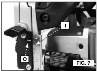
text_image
1 Q 0 FIG. 7RÉGLAGE DE L'ANGLE (FIG. 8-11)
text_image
0 DEGREES R T K L S FIG. 8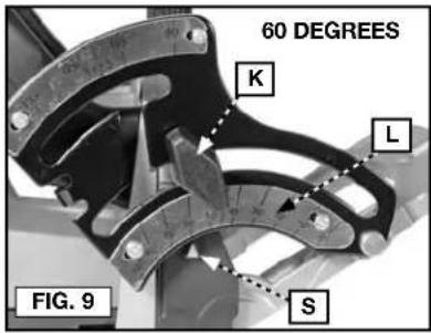
text_image
60 DEGREES K L S FIG. 9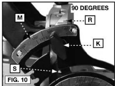
text_image
90 DEGREES M R K S FIG. 10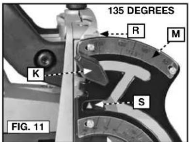
text_image
135 DEGREES R M K S FIG. 11RÉGLAGE DE PRÉCISION (POSITION DE 90°)
text_image
G FIG. 13
text_image
FIG. 14 Xtext_image
W FIG. 15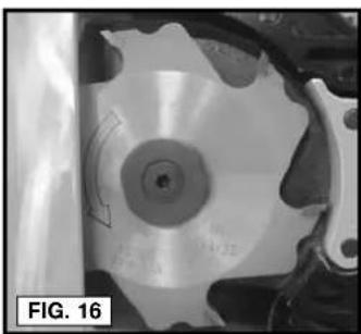
natural_image
Close-up of a mechanical component with a circular disc and curved arrow indicating rotation (no text or symbols)UTILISATION DE LAME DE 50,8 MM (2 PO) (FIG.12-15, 17-21)
natural_image
Close-up of a mechanical component with a circular feature and curved features, labeled 'FIG. 17' (no readable text or symbols)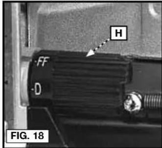
text_image
H FF D FIG. 18natural_image
Close-up of a hand holding a small mechanical component, no visible text or symbols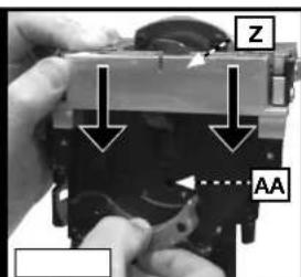
text_image
Z AA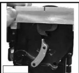
natural_image
Close-up of mechanical components with no visible text or symbolstext_image
BB FIG. 22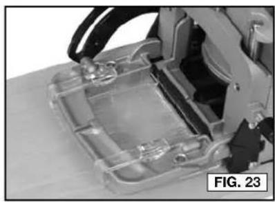
natural_image
Close-up of a transparent plastic electronic device with internal components, labeled 'FIG. 23' (no readable text or symbols on the device itself)natural_image
Mechanical assembly with a block and mechanical components, no visible text or symbolsnatural_image
Close-up of hands using a tool to work on wooden blocks, no visible text or symbols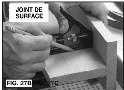
text_image
JOINT DE SURFACE FIG. 27B FIG. 27C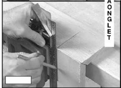
natural_image
Close-up of hands using a measuring tool to cut or mark wood edges, with no visible text or symbolsnatural_image
Person using a power tool on a cutting board, no visible text or symbolsnatural_image
Three-panel image showing a wooden frame with cutouts and hatching, labeled 'FIG. 30' (no text or symbols on the frames themselves)text_image
HH II FIG. 31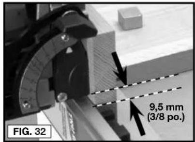
text_image
9,5 mm (3/8 po.) FIG. 32natural_image
Close-up of a wooden plank with visible grain and cutouts, labeled 'FIG. 34' (no other text or symbols)natural_image
Close-up of a hand using a power tool to adjust or install a mechanical component (no visible text or symbols)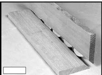
natural_image
Close-up of two wooden planks with visible cutting edge and surface wear (no text or symbols)GUIDE DE DEPANNAGE
DÉMARRAGE IMPOSSIBLE
⚠ WARNING: Never modify the power tool or any part of it. Damage or personal injury could result.
text_image
FIG. 1 A B C J I PORTER CABLE H G F E M A K LENSAMBLE
natural_image
Top-down schematic of a boat hull with patterned hull and side compartments (no text or symbols)0#FF

natural_image
Top-down schematic of a boat hull with hatched sections and center marked (no text or symbols)10 #20
natural_image
Simple line drawing of an oval shape with a central horizontal bar and cross-hatched pattern (no text or symbols)OPERACIÓN
ADVERTENCIA:
text_image
D E FIG. 3text_image
A J FIG. 6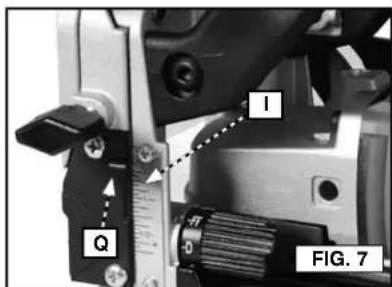
text_image
I Q FIG. 7AJUSTE DEL ÁNGULO (FIG. 8-11)
text_image
0 DEGREES R T K L S FIG. 8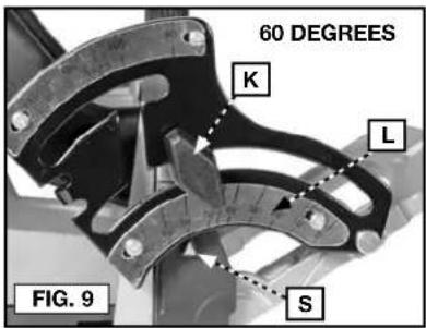
text_image
60 DEGREES K L S FIG. 9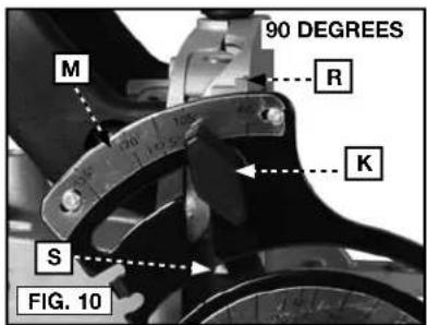
text_image
90 DEGREES M R K S FIG. 10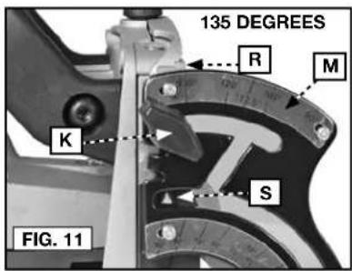
text_image
135 DEGREES R M K S FIG. 11text_image
G FIG. 13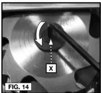
text_image
X FIG. 14natural_image
Close-up of a mechanical component with labeled feature 'W' and directional arrow, no readable text or symbols beyond labels
natural_image
Close-up of a mechanical component with a circular feature and curved arrow, labeled 'FIG. 16' (no readable text or symbols)PARA USAR LA CUCHILLA DE 50,8 MM (2") (FIG. 12-15, 17-21)
natural_image
Close-up of a mechanical component with a circular feature and curved arrow, labeled 'FIG. 17' (no readable text or symbols)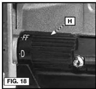
text_image
H FF D FIG. 18natural_image
Close-up of a mechanical component being held, no visible text or symbols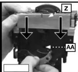
text_image
Z AA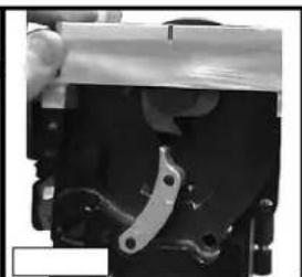
natural_image
Close-up of a mechanical component with metallic clamping mechanism (no visible text or symbols)text_image
BB FIG. 22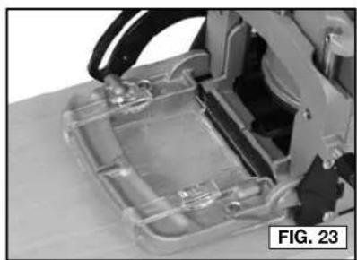
natural_image
Close-up of a transparent plastic enclosure with internal components, no visible text or symbolsnatural_image
Mechanical assembly with a robotic arm and a small block, labeled 'FIG. 26' (no readable text or symbols)BISAGRAS "DUPLEX" (FIG. 26)
natural_image
Close-up of hands using a wooden saw to cut wood grain, with no visible text or symbols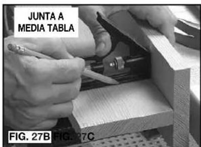
text_image
JUNTA A MEDIA TABLA FIG. 27B FIG. 27C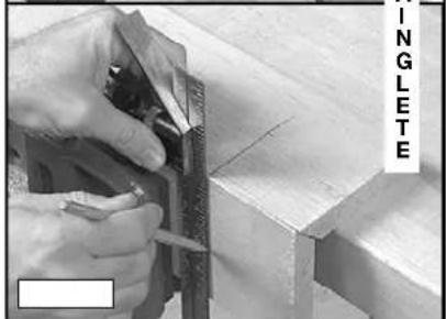
natural_image
Close-up of hands using a measuring tool to cut or mark wood edges, no visible text or symbolsnatural_image
Person using a power saw on a cutting board, no visible text or symbolsnatural_image
Close-up of wooden grain structure with visible grain patterns and a label 'FIG. 30' (no other text or symbols)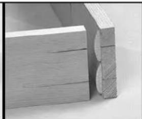
natural_image
Close-up of a wooden frame with visible grain and cutouts (no text or symbols)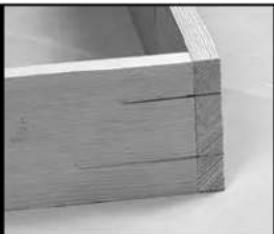
natural_image
Close-up of a wooden drawer or shelf with visible grain and texture (no text or symbols)JUNTAS ("T") DE SUPERFICIE
text_image
HH II FIG. 31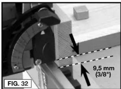
text_image
FIG. 32 9,5 mm (3/8")natural_image
Close-up of a wooden plank with visible grain and cutouts, labeled 'FIG. 34' (no other text or symbols)natural_image
Two-panel image showing a hand operating a tool and a wooden plank with cutouts (no text or symbols visible)Local D, Col. Obrera (55) 5588 9377
MERIDA, YUC
Calle 63 #459-A - Col. Centro (999) 928 5038
MONTERREY, N.L.
Av. Francisco I. Madero 831 Poniente - Col. Centro (818) 375 23 13
PUEBLA, PUE
17 Norte #205 - Col. Centro (222) 246 3714
QUERETARO, QRO
Av. San Roque 274 - Col. San Gregorio (442) 2 17 63 14
SAN LUIS POTOSI, SLP
natural_image
Blank white image with no visible content, text, or symbols.
natural_image
Blank white image with no visible content, text, or symbols.
natural_image
Blank white image with no visible content, text, or symbols.
natural_image
Blank white image with no visible content, text, or symbols.
natural_image
Blank white image with no visible content, text, or symbols.
natural_image
Blank white image with no visible content, text, or symbols.
natural_image
Blank white image with no visible content, text, or symbols.
natural_image
Blank white image with no visible content, text, or symbols.
natural_image
Blank white image with no visible content, text, or symbols.
natural_image
Blank white image with no visible content, text, or symbols.
natural_image
Blank white image with no visible content, text, or symbols.
natural_image
Blank white image with no visible content, text, or symbols.
natural_image
Blank white image with no visible content, text, or symbols.
natural_image
Blank white image with no visible content, text, or symbols.
natural_image
Blank white image with no visible content, text, or symbols.
natural_image
Blank white image with no visible content, text, or symbols.
natural_image
Blank white image with no visible content, text, or symbols.
natural_image
Blank white image with no visible content, text, or symbols.
natural_image
Blank white image with no visible content, text, or symbols.
natural_image
Blank white image with no visible content, text, or symbols.
natural_image
Blank white image with no visible content, text, or symbols.
natural_image
Blank white image with no visible content, text, or symbols.
natural_image
Blank white image with no visible content, text, or symbols.
natural_image
Blank white image with no visible content, text, or symbols.
natural_image
Blank white image with no visible content, text, or symbols.
natural_image
Blank white image with no visible content, text, or symbols.
natural_image
Blank white image with no visible content, text, or symbols.
natural_image
Blank white image with no visible content, text, or symbols.
natural_image
Blank white image with no visible content, text, or symbols.
natural_image
Blank white image with no visible content, text, or symbols.
natural_image
Blank white image with no visible content, text, or symbols.
natural_image
Blank white image with no visible content, text, or symbols.
natural_image
Blank white image with no visible content, text, or symbols.
natural_image
Blank white image with no visible content, text, or symbols.
natural_image
Blank white image with no visible content, text, or symbols.
natural_image
Blank white image with no visible content, text, or symbols.
natural_image
Blank white image with no visible content, text, or symbols.
natural_image
Blank white image with no visible content, text, or symbols.
natural_image
Blank white image with no visible content, text, or symbols.
natural_image
Blank white image with no visible content, text, or symbols.
natural_image
Blank white image with no visible content, text, or symbols.
natural_image
Blank white image with no visible content, text, or symbols.| 62 |

natural_image
Two pairs of horizontal lines, one solid and one dashed, on a white background (no text or symbols)| 1 | |
| 2 | 2 |
| 3 | 3 |
| 4 | 4 |
| 5 | 5 |
| 6 | 6 |
| 7 | 7 |
| 8 | 8 |
| 9 | 9 |
| 10 | 10 |
| 11 | 11 |
| 12 | 12 |
| 13 | 13 |
| 14 | 14 |
| 15 | 15 |
| 16 | 16 |
| 17 | 17 |
| 18 | 18 |
| 19 | 19 |
| 20 | 20 |
| 21 | 21 |
| 22 | 22 |
| 23 | 23 |
| 24 | 24 |
| 25 | 25 |
| 26 | 26 |
| 27 | 27 |
| 28 | 28 |
| 29 | 29 |
| 30 | 30 |
| 31 | 31 |
| 32 | 32 |
| 33 | 33 |
| 34 | 34 |
| 35 | 35 |
| 36 | 36 |
| 37 | 37 |
| 38 | 38 |
| 39 | 39 |
| 40 | 40 |
| 41 | 41 |
| 42 | 42 |
| 43 | 43 |
| 44 | 44 |
| 45 | 45 |
| 46 | 46 |
| 47 | 47 |
| 48 | 48 |
| 49 | 49 |
| 50 | 50 |
| 51 | 51 |
| 52 | 52 |
| 53 | 53 |
| 54 | 54 |
| 55 | 55 |
| 56 | 56 |
| 57 | 57 |
| 58 | 58 |
| 59 | 59 |
| 60 | 60 |
| 61 | 61 |
| 62 | 62 |
| 63 | 63 |
| 64 | 64 |
| 65 | 65 |
| 66 | 66 |
| 67 | 67 |
| 68 | 68 |
| 69 | 69 |
| 70 | 70 |
| 71 | 71 |
| 72 | 72 |
| 73 | 73 |
| 74 | 74 |
| 75 | 75 |
| 76 | 76 |
| 77 | 77 |
| 78 | 78 |
| 79 | 79 |
| 80+ (continued) | |


natural_image
Blank white image with no visible content, text, or symbols.
natural_image
Blank white image with no visible content, text, or symbols.
natural_image
Blank white image with no visible content, text, or symbols.
natural_image
Blank white image with no visible content, text, or symbols.
natural_image
Blank white image with no visible content, text, or symbols.
natural_image
Blank white image with no visible content, text, or symbols.
natural_image
Blank white image with no visible content, text, or symbols.
natural_image
Blank white image with no visible content, text, or symbols.

text_image
_ | | _
natural_image
Blank white image with no visible content, text, or symbols.
natural_image
Blank white image with no visible content, text, or symbols.
natural_image
Blank white image with no visible content, text, or symbols.
natural_image
Blank white image with no visible content, text, or symbols.
natural_image
Blank white image with no visible content, text, or symbols.
natural_image
Blank white image with no visible content, text, or symbols.
natural_image
Blank white image with no visible content, text, or symbols.
natural_image
Blank white image with no visible content, text, or symbols.
natural_image
Blank white image with no visible content, text, or symbols.
natural_image
Blank white image with no visible content, text, or symbols.
natural_image
Blank white image with no visible content, text, or symbols.
natural_image
Blank white image with no visible content, text, or symbols.
natural_image
Blank white image with no visible content, text, or symbols.
natural_image
Blank white image with no visible content, text, or symbols.
natural_image
Blank white image with no visible content, text, or symbols.
natural_image
Blank white image with no visible content, text, or symbols.
natural_image
Blank white image with no visible content, text, or symbols.
natural_image
Blank white image with no visible content, text, or symbols.
natural_image
Blank white image with no visible content, text, or symbols.
natural_image
Blank white image with no visible content, text, or symbols.
natural_image
Blank white image with no visible content, text, or symbols.
natural_image
Blank white image with no visible content, text, or symbols.
natural_image
Blank white image with no visible content, text, or symbols.
natural_image
Blank white image with no visible content, text, or symbols.
natural_image
Blank white image with no visible content, text, or symbols.
natural_image
Blank white image with no visible content, text, or symbols.
natural_image
Blank white image with no visible content, text, or symbols.
natural_image
Blank white image with no visible content, text, or symbols.
natural_image
Blank white image with no visible content, text, or symbols.
natural_image
Blank white image with no visible content, text, or symbols.
natural_image
Blank white image with no visible content, text, or symbols.
natural_image
Blank white image with no visible content, text, or symbols.
natural_image
Blank white image with no visible content, text, or symbols.
natural_image
Blank white image with no visible content, text, or symbols.
natural_image
Blank white image with no visible content, text, or symbols.
natural_image
Blank white image with no visible content, text, or symbols.
natural_image
Blank white image with no visible content, text, or symbols.
natural_image
Blank white image with no visible content, text, or symbols.
natural_image
Blank white image with no visible content, text, or symbols.
natural_image
Blank white image with no visible content, text, or symbols.
natural_image
Blank white image with no visible content, text, or symbols.
natural_image
Blank white image with no visible content, text, or symbols.| 63 | |
| 2018 | 1,574 |
| 2019 | 1,604 |
| 2020 | 1,634 |
| 2021 | 1,664 |

natural_image
Two pairs of horizontal lines, one solid and one dashed, on a white background (no text or symbols)| 1 | |
| 2 | 2 |
| 3 | 3 |
| 4 | 4 |
| 5 | 5 |
| 6 | 6 |
| 7 | 7 |
| 8 | 8 |
| 9 | 9 |
| 10 | 10 |
| 11 | 11 |
| 12 | 12 |
| 13 | 13 |
| 14 | 14 |
| 15 | 15 |
| 16 | 16 |
| 17 | 17 |
| 18 | 18 |
| 19 | 19 |
| 20 | 20 |
| 21 | 21 |
| 22 | 22 |
| 23 | 23 |
| 24 | 24 |
| 25 | 25 |
| 26 | 26 |
| 27 | 27 |
| 28 | 28 |
| 29 | 29 |
| 30 | 30 |
| 31 | 31 |
| 32 | 32 |
| 33 | 33 |
| 34 | 34 |
| 35 | 35 |
| 36 | 36 |
| 37 | 37 |
| 38 | 38 |
| 39 | 39 |
| 40 | 40 |
| 41 | 41 |
| 42 | 42 |
| 43 | 43 |
| 44 | 44 |
| 45 | 45 |
| 46 | 46 |
| 47 | 47 |
| 48 | 48 |
| 49 | 49 |
| 50 | 50 |
| 51 | 51 |
| 52 | 52 |
| 53 | 53 |
| 54 | 54 |
| 55 | 55 |
| 56 | 56 |
| 57 | 57 |
| 58 | 58 |
| 59 | 59 |
| 60 | 60 |
| 61 | 61 |
| 62 | 62 |
| 63 | 63 |
| 64 | 64 |
| 65 | 65 |
| 66 | 66 |
| 67 | 67 |
| 68 | 68 |
| 69 | 69 |
| 70 | 70 |
| 71 | 71 |
| 72 | 72 |
| 73 | 73 |
| 74 | 74 |
| 75 | 75 |
| 76 | 76 |
| 77 | 77 |
| 78 | 78 |
| 79 | 79 |
| 80+ |


natural_image
Blank white image with no visible content, text, or symbols.
natural_image
Blank white image with no visible content, text, or symbols.
natural_image
Blank white image with no visible content, text, or symbols.
natural_image
Blank white image with no visible content, text, or symbols.
natural_image
Blank white image with no visible content, text, or symbols.
natural_image
Blank white image with no visible content, text, or symbols.
natural_image
Blank white image with no visible content, text, or symbols.
natural_image
Blank white image with no visible content, text, or symbols.
The following are PORTER-CABLE trademarks for one or more power tools and accessories: a gray and black color scheme; a “four point star” design; and three contrasting/outlined longitudinal stripes.