
ST7700 - Hedge trimmers BLACK & DECKER - Free user manual and instructions
Find the device manual for free ST7700 BLACK & DECKER in PDF.

| Product Type | Edger / Electric String Trimmer |
| Brand | Black & Decker |
| Model | ST7700 |
| Power Source | Electric corded (120 V, 60 Hz) |
| Cutting Line Diameter | 1.65 mm (0.065 in) round nylon monofilament |
| Spool Capacity | 6 m (20 ft) of line |
| Usage Modes | Edging and trimming for maintenance (pivoting head) |
| Line Feed System | Automatic with built-in cutter |
| Safety Features | Line guard, two-hand switch, polarized plug |
| Required Protective Equipment | Safety glasses, gloves, non-slip shoes, hearing protection |
| Maintenance | Cleaning with a damp cloth and mild soap |
| Recommended Replacement Spool | Black & Decker AF-100 |
| Warranty | 2 years for household use |
| Compatible Catalog Numbers | ST4500, ST7600, ST7700 |
Frequently Asked Questions - ST7700 BLACK & DECKER
User questions about ST7700 BLACK & DECKER
0 question about this device. Answer the ones you know or ask your own.
Ask a new question about this device
Download the instructions for your Hedge trimmers in PDF format for free! Find your manual ST7700 - BLACK & DECKER and take your electronic device back in hand. On this page are published all the documents necessary for the use of your device. ST7700 by BLACK & DECKER.
USER MANUAL ST7700 BLACK & DECKER
Catalog Numbers ST4500, ST7600, ST7700
Thank you for choosing Black & Decker! Go to
www.BlackandDecker.com/NewOwner to register your new product.
PLEASE READ BEFORE RETURNING THIS PRODUCT FOR ANY REASON:
If you have a question or experience a problem
with your Black & Decker purchase, go to
HTTP://WWW.BLACKANDDECKER.COM/INSTANTANSWERS
for instant answers 24 hours a day.
If you can't find the answer or do not have access to the internet,
call 1-800-544-6986 from 8 a.m. to 5 p.m. EST Mon. -- Fri. to speak
with an agent. Please have the catalog number available when you call.
SAVE THIS MANUAL FOR FUTURE REFERENCE.
VEA EL ESPAÑOL EN LA CONTRAPORTADA.
POUR LE FRANÇAIS, VOIR LA COUVERTURE ARRIÈRE.
- Attach guard before trimming or edging.
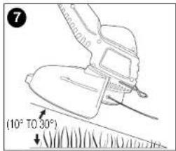
- Angle tool slightly (10° to 30°) when trimming.
Date Code:
natural_image
Line drawing of a handheld vacuum cleaner (no text or symbols)SAFETY GUIDELINES - DEFINITIONS
It is important for you to read and understand this manual. The information it contains relates to protecting YOUR SAFETY and PREVENTING PROBLEMS. The symbols below are used to help you recognize this information.
⚠️ DANGER:
situation which, if not avoided, will result in death or serious injury.
⚠ WARNING:
Indicates a potentially hazardous
[Non-Text]
situation which, if not avoided, could result in death or serious injury.
⚠️ CAUTION:
ndicates a potentially hazardous situation
which, if not avoided, may result in minor or moderate injury.
CAUTION:
d without the safety alert symbol indicates
a potentially hazardous situation which, if not avoided, may result in property damage.
⚠ WARNING: IMPORTANT SAFETY WARNINGS AND INSTRUCTIONS
⚠ WARNING:
When using gardening appliances, basic
safety precautions should always be followed to reduce risk of fire electric shock, and personal injury, including the following.
⚠ WARNING
Some dust created by this product
contains chemicals known to the State of California to cause cancer, birth defects or other reproductive harm. Some examples of these chemicals are:
• compounds in fertilizers
• compounds in insecticides, herbicides and pesticides
• arsenic and chromium from chemically treated lumber
To reduce your exposure to these chemicals, wear approved safety equipment such as dust masks that are specially designed to filter out microscopic particles.
⚠ WARNING:
Wear appropriate personal hearing
protection during use. Under some conditions and duration of use, noise from this product may contribute to hearing loss.
READ ALL INSTRUCTIONS
- Before any use, be sure everyone using this garden appliance reads and understands all safety instructions and other information contained in this manual.
- Save these instructions and review frequently prior to use and in instructing others.
GENERAL SAFETY WARNINGS AND
INSTRUCTIONS FOR ALL APPLIANCES
- AVOID DANGEROUS ENVIRONMENT. Don't use appliances in damp or wet locations. Don't use appliances in the rain.
- KEEP CHILDREN AWAY. All visitors should be kept at a distance from work area.
- STORE IDLE APPLIANCES INDOORS. When not in use, appliances should be stored indoors in dry, and high or locked-up place – out of reach of children.
- DON'T FORCE APPLIANCE. It will do the job better and with less likelihood of a risk of injury at the rate for which it was designed.
- USE RIGHT APPLIANCE. Do not use the appliance for any job except that for which it is intended.
- DRESS PROPERLY. Do not wear loose clothing or jewelry. They can be caught in moving parts. Rubber gloves and substantial, nonskid footwear are recommended when working outdoors. Wear protective hair covering to contain long hair.
- USE SAFETY GLASSES AND OTHER SAFETY EQUIPMENT. Use safety goggles or safety glasses with side shields, complying with applicable safety standards and, when needed, a face shield. Also use face or dust mask if operation is dusty. This applies to all
persons in the work area. Also use a hard hat, hearing protection, gloves, safety shoes and dust collection systems when specified or required. Safety glasses or the like are available at extra cost at your local dealer or Black & Decker Service Center.
- DON'T ABUSE CORD. Never carry appliance by cord or yank it to disconnect from receptacle. Keep cord from heat, oil, and sharp edges.
- DON'T OVERREACH. Keep proper footing and balance at all times.
- MAINTAIN APPLIANCE WITH CARE. Keep cutting edge sharp and clean for best performance and to reduce the risk of injury. Follow instructions for lubricating and changing accessories. Inspect appliance cord periodically and if damaged, have it repaired by authorized service facility. Inspect extension cords periodically and replace if damaged. Keep handles dry, clean, and free from oil and grease.
- DISCONNECT APPLIANCES. Disconnect the appliance from the power supply when not in use, before servicing, and when changing accessories such as blades and the like.
- AVOID UNINTENTIONAL STARTING. Don't carry plugged-in appliance with finger on switch. Be sure switch is off when plugging in.
- GROUND FAULT CIRCUIT INTERRUPTER (GFCI) protection should be provided on the circuits or outlets to be used for the gardening appliance. Receptacles are available having built in GFCI protection and may be used for this measure of safety.
- STAY ALERT. Watch what you are doing. Use common sense. Do not operate appliance when you are tired.
- CHECK DAMAGED PARTS. Before further use of the appliance, a guard or other part that is damaged should be carefully checked to determine that it will operate properly and perform its intended function. Check for alignment of moving parts, binding of moving parts, breakage of parts, mounting and any other conditions that may affect its operation. A guard or other part that is damaged should be properly repaired or replaced by an authorized service center unless otherwise indicated elsewhere in this manual.
- USE OF ACCESSORIES AND ATTACHMENTS. The use of any
accessory or attachment not recommended for use with this appliance could be hazardous. Note: Refer to the accessory section of this manual for further details.
- EXTENSION CORDS. Make sure your extension cord is in good condition. When using an extension cord, be sure to use one heavy enough to carry the current your product will draw. An undersized extension cord will cause a drop in line voltage resulting in loss of power and overheating. The table below shows the correct size to use depending on cord length and nameplate ampere rating. If in doubt, use the next heavier gauge. The smaller the gauge number, the heavier the cord. To reduce the risk of disconnection of the appliance from the extension cord during operation, use the extension cord retainer described in this manual.
| Minimum Gauge for Cord SetsVolts Total Length of Cord in Feet120V 0-25 26-50 51-100 101-150(0-7,6m) (7,6-15,2m) (15,2-30,4m) (30,4-45,7m) | |||||||
| Ampere RatingMore Not more American Wire GaugeThan Than | |||||||
| 0 | - | 6 | 1 | 8 | 1 | 6 | 1 |
| 6 | - | 10 | 18 | 16 | 14 | 12 | |
| 10 | - | 12 | 16 | 16 | 14 | 12 | |
| 12 | - | 16 | 14 | 12 | Not Recommended | ||
⚠ WARNING: OUTDOOR USE EXTENSION CORDS To reduce the risk of electric shock, use only with an extension cord intended for outdoor use, such as an extension cord of type SW-A, SOW-A, STW-A, STOW-A, SJW-A, SJOW-A, SJTW-A, or SJTOW-A.
- REPAIRS AND SERVICE. Repairs, maintenance and any adjustments not specified in this manual should be performed by Black & Decker authorized service centers or other qualified service organizations, always using identical replacement parts.
⚠️ IMPORTANT WARNINGS FOR STRING TRIMMERS
- Use the proper size and type of cutting line. Do not use metal wire, rope or the like. Do not use cutting line heavier than that recommended by the manufacturer. See the accessory section of this manual for more detailed information about the proper cutting line to use.
- Keep the cutting line trimmed to the proper length (done automatically by the appliance). Make sure that the guard is firmly in place, in working order and positioned between yourself and the cutting line.
- Wear long pants and substantial footwear to protect yourself from injury caused by flying debris. This is especially important when edging with the appliance.
⚠ SAFETY WARNINGS AND INSTRUCTIONS: POLARIZED PLUGS
To reduce the risk of electric shock, this equipment has a polarized plug (one blade is wider than the other). This equipment must be used with a suitable polarized 2 wire or 3 wire extension cord. Polarized connections will fit together only one way. Make sure that the receptacle end of the extension cord has large and small blade slot widths. If the plug does not fit fully into the extension cord, reverse the plug. If it still does not fit, obtain a suitable extension cord. If the extension cord does not fit fully into the outlet, contact a qualified electrician to install the proper outlet. Do not change the tool plug or extension cord in any way.
SAVE THESE INSTRUCTIONS
ASSEMBLY INSTRUCTIONS
ATTACHING THE GUARD AND EDGE GUIDE TO THE TRIMMER/EDGER
WARNING: The guard must always be on the tool to protect the user. NEVER OPERATE TOOL WITHOUT GUARD EIRMLY IN PLACE.
Unplug the tool before attempting to attach the guard.
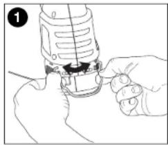
- Locate the edge guide and spread it apart as shown in figure 1.
-
Attach the edge guide to the housing by locating the two ends into the holes in the housing.
-
See figure 2 for edge guide assembled on the trimmer.
natural_image
Line drawing of hands using a sewing machine to adjust or install a component (no text or symbols visible)
natural_image
Line drawing of a device with a cable inserted into a housing (no text or symbols)90556352 ST4500.qxd: chainsaw booklet new 10/20/09 8:03 AM Page 5
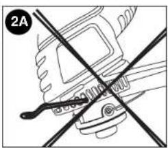
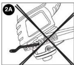
DO NOT INSERT THE ENDS OF THE EDGE GUIDE INTO THE FAN HOLES AS SHOWN IN FIGURE 2A.
natural_image
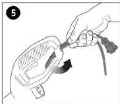
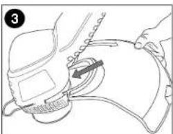
Diagram of a hand holding a tool with intersecting lines, no text or symbols present- Attach extension cord to cord retainer as shown in figures 5 & 6.
natural_image
Illustration of a hand holding a tool interacting with a device (no text or symbols visible)- Remove the guard attachment screw from the guard. Slip the guard onto the trimmer housing and lineup the screw hole in the guard with the screw hole in the housing (figure 3).
natural_image
Line drawing of a medical procedure with a hand holding a tool, no text or symbols present
natural_image
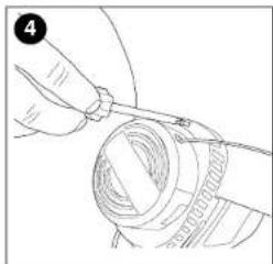
Illustration of a hand holding a medical device with a cable (no text or symbols visible)- Insert the guard attachment screw to secure the guard in place as shown in figure 4.
natural_image
Line drawing of a hand holding a cable or wire component, no text or symbols presentOPERATING INSTRUCTIONS FOR CATALOG # ST4500 BUMP FEED TRIMMER LINE FEED
Your trimmer uses .065 in. (1.65 mm) diameter, ROUND nylon line to cut grass and weeds quickly and easily. Cutting line will wear faster and require more feeding if the cutting or edging is done along sidewalks or other abrasive surfaces or heavier weeds are being cut. As you use the trimmer, the string will get shorter due to wear. Gently bump the unit on the ground and the line will feed.
⚠️ CAUTION: ALWAYS USE EYE PROTECTION.
90556352 ST4500.qxd: chainsaw booklet new 10/20/09 8:03 AM Page 6
⚠️ CAUTION: Inspect area to be trimmed and remove any wire, cord, or string-like objects which could become entangled in the rotating line or spool. Be particularly careful to avoid any wire which might be bent outwardly into the path of the tool, such as barbs at the base of a chain link fence.
-
Angle unit as shown in figure 7.
-
Slowly swing trimmer side-to-side as shown in figure 8.

natural_image
Line drawing of a person using a power tool on grass, with arrows indicating motion (no text or symbols)-
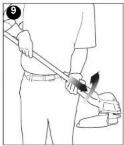
To convert for maintenance edging, turn off the tool. Holding the trimmer (as shown in figure 9) with one hand by the auxiliary handle, grasp the trimmer head collar, push in direction of arrow and rotate the trimmer head clockwise (when viewed from the switch end) until it stops, (half turn), release your hand. The tool is locked in the edger position.
-
To operate as a maintenance edger, position trimmer above sidewalk as shown in figure 10.
- Return to trimming position by turning the tool off, pushing in direction of arrow and rotating the trimmer head counter clockwise until it stops.
natural_image
Line drawing of a person using a tool to apply or install a component (no text or symbols present)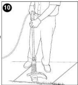
natural_image
Line drawing of a person using a manual cleaning tool on a tiled floor (no text or symbols)6
RELOADING LINE ST4500
USE ONLY .065 in. (1.65mm) DIAMETER NYLON
MONOFILAMENT LINE. Heavier line will overload the motor and cause overheating. This line is available at your local dealer or authorized service center.
Do not use fishing line or other lines that are not recommended.
- Unplug extension cord at trimmer.
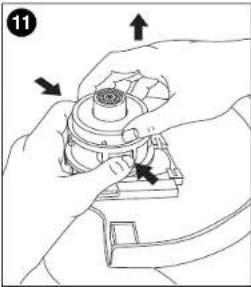
- Remove the bump cap by pulling up while depressing the two release tabs on the sides of the hub at the points shown in figure 11.
NOTE: It may be necessary to pull up on the cap while depressing the release tabs one side at a time.
- Remove any broken cutting line, wrap the remaining line tight and reinsert spool into hub as follows.
a. Wind the line tight enough so that it is all below the edges of the flanges on the spool. If it extends past the flanges, it won't fit into the hub.
b. Place the loose end of the cutting line through the gap in the spool flange as shown in figure 12. (Either gap will do but try to leave yourself about 3 or 4 inches of line to work with.)
natural_image
Illustration of hands assembling a mechanical component with arrows indicating assembly direction (no text or symbols)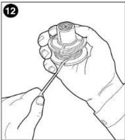
natural_image
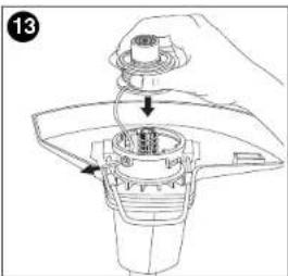
Line drawing of a hand holding a mechanical component with a screw-like base (no text or symbols)c. Holding the line in the gap, insert the end through the eyelet in the hub and slip the spool into the hub, as shown in figure 13.
Make sure the spring is still in place in the hub. If the spool does not slip into the hub easily, press gently and pull straight out on the cutting line that protrudes through the eyelet.
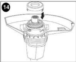
4. Once the spool drops into the hub, align the release tabs on the shroud with the slots in the hub as shown in figure 14 and press the shroud into place. Be sure that both release tabs snap into place.
5. To replace the line on a spool, follow the steps below
a. Locate, on the empty spool, one of the two small holes shown in figure 15.
natural_image
Technical line drawing of a mechanical component with a central hub and mounting bracket (no text or symbols)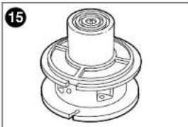
natural_image
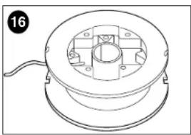
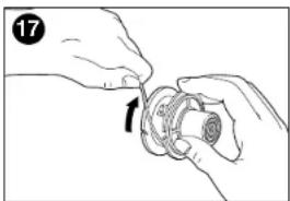
Technical line drawing of a mechanical component with concentric rings and flanges (no text or symbols)b. Insert the end of the line no more than 1/8 in. into the hole and begin winding the line around the spool (figure 16).
natural_image
Technical line drawing of a mechanical component with a central hub and mounting holes (no text or symbols)Be sure to wind the line in the direction of the arrow in figure 17. Do not overfill spool. The spool holds 20 feet (6 m) of line. c. Perform steps 3 and 4 above.
natural_image
Illustration of hands assembling a mechanical component (no text or symbols visible)OPERATING INSTRUCTIONS FOR CATALOG # ST7600, ST7700 AUTO FEED SYSTEM LINE FEED
Your trimmer uses .065 in. (1.65 mm) diameter, ROUND nylon line to cut grass and weeds quickly and easily. During use, the tip of the nylon line will become frayed and worn and the special self feeding line hub will automatically feed and trim a fresh length of line. Cutting line will wear faster and require more feeding if the cutting or edging is done along sidewalks or other abrasive surfaces or heavier weeds are being cut. The advanced automatic line feeding mechanism senses when more cutting line is needed and feeds and trims the correct length of line whenever its required. DO NOT BUMP unit on ground in attempt to feed line or for any other purposes.
⚠️ CAUTION: ALWAYS USE EYE PROTECTION.
⚠️CAUTION: Inspect area to be trimmed and remove any wire, cord, or string-like objects which could become entangled in the rotating line or spool. Be particularly careful to avoid any wire which might be bent outwardly into the path of the tool, such as barbs at the base of a chain link fence.
- Angle unit as shown in figure 7.
- Slowly swing trimmer side-to-side as shown in figure 8
- To convert for maintenance edging, turn off the tool. Holding the trimmer (as shown in figure 9) with one hand by the auxiliary handle, grasp the trimmer head collar, push in direction of arrow and rotate the trimmer head clockwise (when viewed from the switch end) until it stops, (half turn), release your hand. The tool is locked in the edger position.
- To operate as a maintenance edger, position trimmer above sidewalk as shown in figure 10.
- Return to trimming position by turning the tool off, pushing in direction of arrow and rotating the trimmer head counter clockwise until it stops.
CLEARING JAMS AND TANGLED LINES
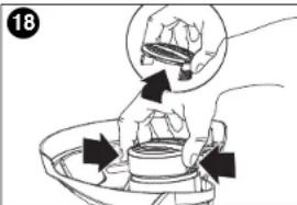
From time to time, especially when cutting thick or stalky weeds, the line feeding hub may become clogged with sap or other material and the line will become jammed as a result. To clear the
- Press the release tabs on the line hub cap, as shown in figure 18 and remove the cap by pulling it straight off.
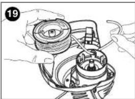
- Lift the spool of nylon line out of the hub and clear any broken line or cutting debris from the spool area. (If you plan to replace the spool or rewind it, this is the place to c
90556352 ST4500.qxd: chainsaw booklet new 10/20/09 8:03 AM Page 9
- Unwrap about one foot (30 cm) of line to ensure that it's undamaged. If it is OK rewind it and insert the line end through the eyelet in the spool hub as shown in figure 19. Pull 4 in. (10 cm) of the line through the hole and maintain tension while placing the spool down into the hub with the arrow up, as shown in figure 20.
- Press the spool down GENTLY and rotate it until you feel it drop into place. (When in place, the spool will turn a few degrees left and right freely). Take care to keep the line from becoming trapped under the spool.
- Snap the hub cap back on, and power the tool on. In a few seconds or less you'll hear the nylon line being cut automatically to the proper length
natural_image
Illustration of hands assembling a mechanical component with no visible text or symbols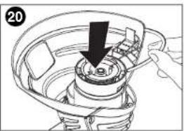
natural_image
Diagram of a hand holding a tool interacting with a mechanical component, showing a downward arrow (no text or symbols present)SPOOL OR LINE REPLACEMENT
USE ONLY .065 in. (1.65mm) DIAMETER NYLON
MONOFILAMENT LINE. Heavier line will overload the motor and cause overheating. This line is available at your local dealer or authorized service center.
Do not use fishing line or other lines that are not recommended.
- Perform step 1 above to remove cap.
- Remove the spool from the tool and remove and discard all line on the spool.
-
Choose either OPTION 1 or OPTION 2 below for spool or line replacement. Perform steps listed under Option 1 or Option 2, then continue with steps 4 through 6 below.
-
Insert the line end through the eyelet in the spool hub, as shown in figure 19. Pull the line through the hole to maintain tension while placing the spool down into the hub, as shown in figure 20.
- Press the spool down GENTLY and rotate it until you feel it drop into place. (When in place, the spool will turn a few degrees left and right freely). Take care to keep the line from becoming trapped under the spool.
- Snap the hub cap back on, and power the tool on. In a few seconds or less you'll hear the nylon line being cut automatically to the proper length.
OPTION 1: ACCESSORY REPLACEMENT SPOOL
Use Black & Decker replacement spool Model No. AF-100. Discard old spool.
OPTION 2: REWINDING SPOOL USING BULK LINE
Bulk line for your trimmer/edger is available at extra cost from your local dealer or Black & Decker Service Center. To install bulk line, follow the steps below. (Use .065 in. diameter ROUND line only)
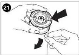
- Insert one end of the bulk line into the hole in the spool as shown in figure 21 about 1/2 in. (12 mm).
- Hold the line in the hole and pull the rest of the line through the slot in the spool.
- Snugly and evenly wind the bulk line onto the spool in the direction of the arrow on the spool until the line builds up to the notches in the spool rim. Do not overfill spool. The spool
natural_image
Illustration of hands holding a mechanical component with directional arrows indicating motion (no text or symbols)90556352 ST4500.qxd: chainsaw booklet new 10/20/09 8:03 AM Page 10
Troubleshooting
Problem Possible Cause Possible Solution
- Unit will not start. - Cord not plugged in. - Plug in cord.
- Circuit fuse is blown. - Replace circuit fuse.
- Circuit breaker. - Reset circuit breaker
is tripped.
- Cord or switch is - Have cord or switch
damaged, replaced at
Black & Decker
Service Center or
Authorized Servicer.
For assistance with your product, visit our website www.blackanddecker.com for the location of the service center nearest you or call the BLACK & DECKER help line at 1-800-544-6986.
MAINTENANCE
CLEANING
Use only mild soap and damp cloth to clean the tool. Never let any liquid get inside the tool; never immerse any part of the tool into a liquid.
IMPORTANT: To assure product SAFETY and RELIABILITY, repairs, maintenance and adjustment should be performed by Black & Decker service centers or other qualified service organizations, always using identical replacement parts.
ACCESSORIES
Recommended accessories for use with your tool are available from your local dealer or authorized service center. If you need assistance regarding accessories, please call: 1-800-544-6986.
WARNING: The use of any accessory not recommended for use with this tool could be hazardous.
SERVICE INFORMATION
Black & Decker offers a full network of company-owned and authorized service locations throughout North America. All Black & Decker Service Centers are staffed with trained personnel to provide customers with efficient and reliable power tool service. Whether you need technical advice, repair, or genuine factory
replacement parts, contact the Black & Decker location nearest you. To find your local service location, refer to the yellow page directory under "Tools—Electric" or call: 1-800-544-6986.
FULL TWO YEAR WARRANTY
Black & Decker (U.S.) Inc. warrants this product for two years against any defects in material or workmanship. The defective product will be replaced or repaired at no charge in either of two ways. The first, which will result in exchanges only, is to return the product to the retailer from whom it was purchased (provided that the store is a participating retailer). Returns should be made within the time period of the retailer's policy for exchanges (usually 30 to 90 days after the sale). Proof of purchase may be required. Please check with the retailer for their specific return policy regarding returns that are beyond the time set for exchanges.
The second option is to take or send the product (prepaid) to a Black & Decker owned or authorized Service Center for repair or replacement at our option. Proof of purchase may be required. Black & Decker owned and authorized Service Centers are listed under "Tools-Electric" in the yellow pages of the phone directory and available on our website www.blackanddecker.com.
This warranty does not apply to accessories. This warranty gives you specific legal rights and you may have other rights which vary from state to state. Should you have any questions, contact the manager of your nearest Black & Decker Service Center.
Free warning label replacement: If your warning labels become illegible or are missing, call 1-800-544-6986 for a free replacement. LATIN AMERICA: This warranty does not apply to products sold in Latin America. For products sold in Latin America, check country specific warranty information contained in the packaging, call the local company or see the website for warranty information.

See 'Tools-Electric' - Yellow Pages - for Service & Sales
Imported by Black & Decker (U.S.) Inc., 701 E. Joppa Rd. Towson, MD 21286 U.S.A.


BLACK&DECKER®
TAILLE-BORDURE/ COUPE-BORDURE MODE D'EMPLOI
natural_image
Line drawing of a handheld soap dispenser with handle and base (no text or symbols)LIGNES DIRECTRICES EN MATIERE DE SECURITE DEFINITIONS
natural_image
Illustration of hands using a power tool to adjust or install a component (no text or symbols visible)90556352 ST4500.qxd: chainsaw booklet new 10/20/09 8:03 AM Page 15
natural_image
Line drawing of a medical device with a clip and attached cable (no text or symbols)natural_image
Line drawing of a hand using a tool to cut or mark a circular object (no text or symbols)NE PAS INSÉRER LES BOUTS DU DISPOSITIF DE GUIDAGE DE BORD DANS LES TROUS DU VENTILATEUR COMME L'ILLUSTRE LA FIGURE 2A.
natural_image
Pure mechanical diagram showing a tool intersecting a gear (no text or symbols)natural_image
Illustration of a hand using a tool to adjust or install a component, no text or symbols present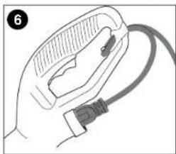
natural_image
Illustration of a hand holding a cable with a connector (no text or symbols)MODE D'EMPLOI POUR LE CATALOGUE No ST4500 TAILLE-BORDURE À ALIMENTATION SACCADÉE
ALIMENTATION CONTINUE
natural_image
Line drawing of a person using a manual power tool on grass, no text or symbols present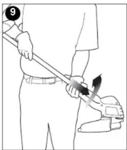
natural_image
Line drawing of a person using a tool to apply a brush (no text or symbols present)natural_image
Line drawing of a person using a manual vacuum cleaner on a tiled floor (no text or symbols)RECHARGEMENT DU FIL ST4500
UTILISER UNIQUEMENT DU FIL DE NYLON MONOFILAMENT
natural_image
Line drawing of a hand holding a cylindrical object with a screwdriver inserted (no text or symbols)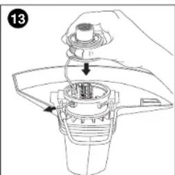
natural_image
Line drawing of a hand holding a mechanical component with arrows indicating motion (no text or symbols)natural_image
Technical line drawing of a mechanical component with a cylindrical shaft and flange (no text or symbols)
natural_image
Technical line drawing of a mechanical component with concentric rings and mounting holes (no text or symbols)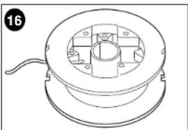
natural_image
Technical line drawing of a mechanical component with a central housing and mounting holes (no text or symbols)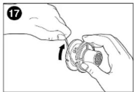
natural_image
Illustration of hands holding a mechanical component with an arrow indicating rotation (no text or symbols)MODE D'EMPLOI POUR LE CATALOGUE NO ST7600, ST7700 SYSTÈME À ALIMENTATION AUTOMATIQUE
ALIMENTATION CONTINUE
natural_image
Illustration of hands assembling a mechanical component with no visible text or symbols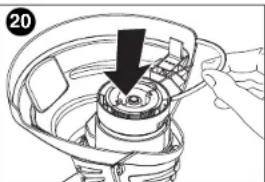
natural_image
Illustration of a hand using a tool to adjust or install a mechanical component, with no visible text or symbols.90556352 ST4500.qxd: chainsaw booklet new 10/20/09 8:03 AM Page 20
natural_image
Illustration of hands performing a mechanical operation with arrows indicating direction (no text or symbols)90556352 ST4500.qxd: chainsaw booklet new 10/20/09 8:03 AM Page 21
ACCESSOIRES
natural_image
Line drawing of a handheld tool with handle and base (no text or symbols)natural_image
Line drawing of a hand using a sewing machine to adjust or install a small component (no text or symbols visible)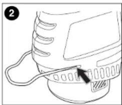
natural_image
Line drawing of a mechanical component with a cable and pin (no text or symbols)90556352 ST4500.qxd: chainsaw booklet new 10/20/09 8:03 AM Page 26
natural_image
Diagram of a mechanical device with intersecting lines and a labeled section (2A), no readable text or symbols present.natural_image
Illustration of hands using a tool to adjust or install a component, no text or symbols present
natural_image
Illustration of a hand holding a medical device with a cable (no text or symbols visible)natural_image
Line drawing of hands holding a mechanical component with a cylindrical part (no text or symbols)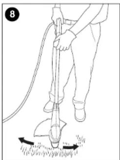
natural_image
Line drawing of a person using a manual push tool on grass, no text or symbols presentnatural_image
Illustration of a person using a power tool to lift a tool, no text or symbols present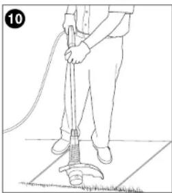
natural_image
Line drawing of a person using a cleaning power tool on a tiled floor (no text or symbols)90556352 ST4500.qxd: chainsaw booklet new 10/20/09 8:03 AM Page 28
CUERDA DE RECARGA ST4500
UTILICE SOLAMENTE CUERDA DE MONOFILAMENTO DE NAILON DE 1,65 mm (0,065 pulg.) DE DIÁMETRO.
natural_image
Line drawing of a hand holding a circular object with a string, no text or symbols present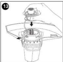
natural_image
Mechanical assembly diagram showing a gear-like component with a central shaft and mounting bracket (no text or symbols)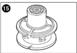
natural_image
Technical line drawing of a mechanical component with concentric rings and mounting holes (no text or symbols)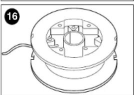
natural_image
Technical line drawing of a mechanical component with a central hub and mounting holes (no text or symbols)natural_image
Illustration of hands assembling a mechanical component (no text or symbols visible)natural_image
Illustration of hands assembling a mechanical component (no text or symbols visible)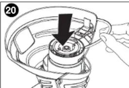
natural_image
Illustration of a hand holding a mechanical component with a black arrow indicating direction (no text or symbols)90556352 ST4500.qxd: chainsaw booklet new 10/20/09 8:03 AM Page 31
natural_image
Illustration of hands holding a mechanical component with directional arrows indicating motion (no text or symbols)90556352 ST4500.qxd: chainsaw booklet new 10/20/09 8:03 AM Page 33
90556352 ST4500.qxd: chainsaw booklet new 10/20/09 8:03 AM Page 34
· GARANTÍA BLACK & DECKER · BLACK & DECKER WARRANTY . SOLAMENTE PARA PROPOSITOS DE MEXICO
Date of purchase · Fecha de compra Invoice No. · No. de factura
PRODUCT INFOMATION · IDENTIFICACION DEL PRODUCTO
Cat. No. · Catalogo ó Modelo Serial Number · No. de serie
90556352 ST4500.qxd: chainsaw booklet new 10/20/09 8:04 AM Page 35
2 AÑOS DE GARANTIA
Col. Fracc. Universidad
Chihuahua, Chihuahua
Tel. 01 614 413 64 04
Fernando González Armenta
Bolivia No. 605
Col. Felipe Carrillo Puerto
Cd. Madero, Tampico
Tel. 01 833 221 34 50
Col. Felipe Carrillo Puerto
Cd. Madero, Tampico
Tel. 01 833 221 34 50
Cat. No. ST4500, ST7600, ST7700 Form No. 90556352 Oct. '09
Copyright© 2009 Black & Decker Printed in China

- SAFETY GUIDELINES - DEFINITIONS
- ⚠️ DANGER:
- ⚠ WARNING:
- ⚠️ CAUTION:
- CAUTION:
- ⚠ WARNING: IMPORTANT SAFETY WARNINGS AND INSTRUCTIONS
- ⚠ WARNING
- READ ALL INSTRUCTIONS
- GENERAL SAFETY WARNINGS AND
- INSTRUCTIONS FOR ALL APPLIANCES
- ⚠️ IMPORTANT WARNINGS FOR STRING TRIMMERS
- ⚠ SAFETY WARNINGS AND INSTRUCTIONS: POLARIZED PLUGS
- SAVE THESE INSTRUCTIONS
- ASSEMBLY INSTRUCTIONS
- ATTACHING THE GUARD AND EDGE GUIDE TO THE TRIMMER/EDGER
- RELOADING LINE ST4500
- USE ONLY .065 in. (1.65mm) DIAMETER NYLON
- OPERATING INSTRUCTIONS FOR CATALOG # ST7600, ST7700 AUTO FEED SYSTEM LINE FEED
- ⚠️ CAUTION: ALWAYS USE EYE PROTECTION.
- CLEARING JAMS AND TANGLED LINES
- SPOOL OR LINE REPLACEMENT
- OPTION 1: ACCESSORY REPLACEMENT SPOOL
- OPTION 2: REWINDING SPOOL USING BULK LINE
- Troubleshooting
- Problem Possible Cause Possible Solution
- MAINTENANCE
- CLEANING
- ACCESSORIES
- SERVICE INFORMATION
- FULL TWO YEAR WARRANTY
- BLACK&DECKER®
- TAILLE-BORDURE/ COUPE-BORDURE MODE D'EMPLOI
- LIGNES DIRECTRICES EN MATIERE DE SECURITE DEFINITIONS
- MODE D'EMPLOI POUR LE CATALOGUE No ST4500 TAILLE-BORDURE À ALIMENTATION SACCADÉE
- ALIMENTATION CONTINUE
- RECHARGEMENT DU FIL ST4500
- UTILISER UNIQUEMENT DU FIL DE NYLON MONOFILAMENT
- MODE D'EMPLOI POUR LE CATALOGUE NO ST7600, ST7700 SYSTÈME À ALIMENTATION AUTOMATIQUE
- ACCESSOIRES
- CUERDA DE RECARGA ST4500
- UTILICE SOLAMENTE CUERDA DE MONOFILAMENTO DE NAILON DE 1,65 mm (0,065 pulg.) DE DIÁMETRO.
- AÑOS DE GARANTIA
Brand : BLACK & DECKER
Model : ST7700
Category : Hedge trimmers