
GE20L08BAR - Boiler GE - Free user manual and instructions
Find the device manual for free GE20L08BAR GE in PDF.

| Product Type | Point-of-Use Electric Water Heater |
| Brand | GE |
| Model | GE20L08BAR |
| Supply Voltage | 240 V / 60 Hz / 1 phase |
| Tank Capacity | 20 gallons (76 L) |
| Rated Power | 2000 W (estimated) |
| Temperature Adjustment Range | 32°C to 66°C (90°F to 150°F) |
| Factory Temperature Setting | 52°C (125°F) |
| Safety Device | High Limit Thermal Cut-off (ECO) with Manual Reset |
| Safety Valve | ANSI Z21.22 Certified Temperature and Pressure (T&P) Relief Valve |
| Tank Material | Glass-Lined Steel |
| Corrosion Protection | Sacrificial Anode Rod |
| Water Connections | 3/4 in NPT (male threads) |
| Maximum Operating Pressure | 150 psi (1.03 MPa) |
| Recommended Maintenance | Annual drain and flush, anode and valve inspection |
| Warranty | 1 year parts and labor, 5 years tank parts |
| Installation | Indoor, on level floor, freeze protection |
| Usage | Residential domestic use |
| Included Accessories | Safety valve, drain valve |
| Tools Required for Installation | Pipe wrench, adjustable wrench, joint compound or Teflon tape |
Frequently Asked Questions - GE20L08BAR GE
User questions about GE20L08BAR GE
0 question about this device. Answer the ones you know or ask your own.
Ask a new question about this device
Download the instructions for your Boiler in PDF format for free! Find your manual GE20L08BAR - GE and take your electronic device back in hand. On this page are published all the documents necessary for the use of your device. GE20L08BAR by GE.
USER MANUAL GE20L08BAR GE
Electronic Residential
WATER HEATERS
SAFETY INFORMATION 3
OPERATINGINSTRUCTIONS.6
CARE AND CLEANING 10
INSTALLATION
INSTRUCTIONS 14
TROUBLESHOOTING TIPS. 18
REPLACEMENT PARTS. 23
WIRING DIAGRAM 18
LIMITED WARRANTY 23
CONSUMER SUPPORT 24
OWNER'S MANUAL
GE Branded Thermostat
Control Point of Use Electric
Water Heater Models.
120 Volt Models:
GE10P08BA*
GE20P08BA*
240 Volt Models:
GE20LO8BA*
FRANCAIS
Write the model and serial numbers here:
Model #
Serial #
You can find them on the rating label on the front side of your water heater.


Certified to NSF/ANSI 372
See http://info.nsf.org/Certified/Lead_
Content/ for specific model listing
THANK YOU FOR MAKING GE APPLIANCES A PART OF YOUR HOME.
Whether you grew up with GE Appliances, or this is your first, we're happy to have you in the family.
We take pride in the craftsmanship, innovation and design that goes into every GE Appliances product, and we think you will too. Among other things, registration of your appliance ensures that we can deliver important product information and warranty details when you need them.
Register your GE appliance now online. Helpful websites and phone numbers are available in the Consumer Support section of this Owner's Manual. You may also mail in the pre-printed registration card included in the packing material.

GE APPLIANCES
IMPORTANT SAFETY INFORMATION READ ALL INSTRUCTIONS BEFORE USING THE APPLIANCE
WARNING
For your safety, the information in this manual must be followed to minimize the risk of fire or explosion, electric shock, or to prevent property damage, personal injury, or loss of life.
Be sure to read and understand the entire Owner's Manual before attempting to install or operate this water heater. It may save you time and cost. Pay particular attention to the Safety Instructions. Failure to follow these warnings could result in serious bodily injury or death. Should you have problems understanding the instructions in this manual, or have any questions, STOP and get help from a qualified service technician or the local electric utility.
WARNING
Risk of Fire - DO NOT store or use gasoline or other flammable vapors and liquids in the vicinity of this or any other appliance. Keep rags and other combustibles away.
WARNING
If the water heater has been subjected to flood, fire, or physical damage, turn off power and water to the water heater.
Do not operate the water heater again until it has been thoroughly checked by qualified service personnel.
Safety Precautions
A. Do turn off power to water heater if it has been subjected to overheating, fire, flood or physical damage.
B. Do Not turn on water heater unless it is filled with water.
C. Do Not turn on water heater if cold water supply shut-off valve is closed.
NOTE: Flammable vapors may be drawn by air currents from surrounding areas to the water heater.
D. If there is any difficulty in understanding or following the Operating Instructions or the Care and Cleaning section, it is recommended that a qualified person or serviceman perform the work.
CAUTION
Risk of Fire - Hydrogen gas can be produced in a hot water system served by this water heater that has not been used for a long period of time (generally two weeks or more). HYDROGEN GAS IS EXTREMELY FLAMMABLE!! To dissipate such gas and to reduce risk of injury, it is recommended that the hot water faucet be opened for several minutes at the kitchen sink before using any electrical appliance connected to the hot water system. If hydrogen is present, there will be an unusual sound such as air escaping through the pipe as the water begins to flow. Do not smoke or use an open flame near the faucet at the time it is open.
FOR INSTALLATIONS IN THE STATE OF CALIFORNIA
California Law requires that residential water heaters must be braced, anchored or strapped to resist falling or horizontal displacement due to earthquake motions. For residential water heaters up to 52 gallon (197 L) capacity, a brochure with generic earthquake bracing instructions can be obtained from: Office of the State Architect, 400 P Street, Sacramento, CA 95814 or you may call 916.324.5315 or ask a water heater dealer.
Applicable local codes shall always govern installation. For residential water heaters of a capacity greater than 52 gallons (197 L) consult the local building jurisdiction for acceptable bracing procedures.
IMPORTANT SAFETY INFORMATION READ ALL INSTRUCTIONS BEFORE USING THE APPLIANCE
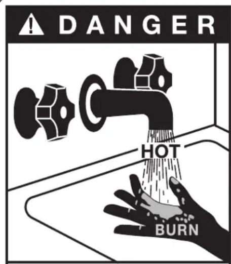
Water temperature over 125^ can cause severe burns instantly or death from scalds.
Temperature control settings usually approximate tap water temperature. However, factors could cause water temperature to reach 160^ regardless of the control settings.
Children, disabled and elderly are at highest risk of being scalded.
See instruction manual before setting temperature at water heater.
Feel water before bathing or showering.
Temperature limiting valves are available; see manual.
WATER TEMPERATURE ADJUSTMENT
Safety, energy conservation, and hot water capacity are factors to be considered when selecting the water temperature setting of the water heater. Water temperatures above 125^ can cause severe burns or death from scalding. Be sure to read and follow the warnings outlined on the label pictured to the left. This label is also located on the water heater near the top of the tank.
Time/Temperature Relationship in Scalds
Temperature Time to Produce a Serious Burn
120°F (49°C) More than 5 minutes
125°F (52°C) 1-1/2 to 2 minutes
130°F (54°C) About 30 seconds
135°F (57°C) About 10 seconds
140^ (60^) Less than 5 seconds
145°F (63°C) Less than 3 seconds
150°F (66°C) About 1-1/2 seconds
155°F (68°C) About 1 second
Table courtesy of Shriners Burn Institute
The chart shown above may be used as a guide in determining the proper water temperature for your home.
DANGER
There is a Hot Water SCALD Potential if the cure thermostat is set too high. Households children, disabled or elderly persons may require for lower thermostat setting to prevent contact over.
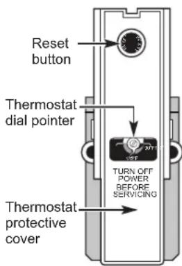
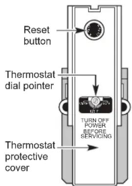
Thermostat has been set at the factory to 125^ (52^) to reduce the risk of scald injury. This is the recommended starting temperature setting, but it can be adjusted to any temperature between 90^ and 150^ (32^ and 66^) .
Water Temperature Setting
The temperature of the water in the water heater can be regulated by setting the temperature dial of the adjustable surface mounted thermostat(s) located behind the jacket access panel(s).
The illustration shows the temperature adjustment dial used for setting the water temperature.
Refer to the Operating Instructions in this manual for detailed instructions how to adjust the thermostat(s).
DANGER
Hotter water
increases the potential for hot water SCALDS.
READ AND SAVE THESE INSTRUCTIONS
IMPORTANT SAFETY INFORMATION READ ALL INSTRUCTIONS BEFORE USING THE APPLIANCE
SAFETY CONTROLS
The water heater is equipped with a combination thermostat and high limit Energy-Cut-Off control (ECO) that is located above the upper heating element in contact with the tank surface. If for any reason the water temperature becomes excessively high, the high limit control (ECO) breaks the power circuit to the heating element. Once the control opens, it must be reset manually. Resetting of the high limit control should be done by a qualified service technician.
CAUTION The cause of the high temperature condition must be investigated by a qualified service technician and corrective action must be taken before placing the water heater in service again.
To reset the temperature-limiting control:
- Turn off the power to the water heater.
- Remove the jacket access panel(s). The thermostat protective cover should not be removed.
- Press the red RESET button.
- Replace the jacket access panel(s) before turning on the power to the water heater.
- Ensure water heater is operating properly after resetting the ECO.
Operating Instructions
Water Heater Capacity and Increasing Temperature Setpoint:
The water heater temperature setting strongly impacts the amount of usable hot water available for showers and baths.
- Safety regulations require a factory setting no greater than 125^ (52^) for all new water heaters. Therefore, if your old water heater was set to a hotter temperature than your new water heater with a factory set setpoint of 125^ (52^) , the new water heater may seem to provide lower capacity than your old water heater. This can be corrected by increasing the temperature setpoint.
- If more hot water capacity is desired, increasing the temperature from 125^ to 135^ ( 52^ to 57^ ) will enable the same tank of hot water to last about 25% longer because less hot water is mixed in at the shower or faucet.
- Increasing the water temperature setpoint may improve the cleaning performance of dishwashers and washing machines.
- The user can adjust the temperature setting to meet their needs. Always read and understand the safety instructions contained in the owner's manual before adjusting the temperature setpoint.
If Adjustment is necessary:
- Turn off the power to the water heater.
- Remove the jacket access panel(s) exposing the thermostat(s). The thermostat protective cover(s) should not be removed.
- Using a small screwdriver, set the thermostat(s) dial pointer(s) to the desired temperature.
- Replace the jacket access panel(s). Turn on the power to the water heater
Mixing Valves
- Mixing valves for reducing point-of-use water temperature by mixing hot and cold water in branch water lines are commercially available. Contact a licensed plumber of the local plumbing authority for further information.
Extended Shutdown Periods
If the water heater is to remain idle for an extended period of time, the power and water to the appliance should be turned off and the water heater drained to conserve energy and prevent a buildup of dangerous hydrogen gas. This unit has no power button, power can only be shut off at the circuit breaker or disconnect switch.
The water heater and piping should be drained if they might be subjected to freezing temperatures.
After a long shutdown period, the water heater's operation and controls should be checked by qualified service personnel. Make certain the water heater is completely filled again before placing it in operation.
NOTE: Refer to the Hydrogen Gas Caution in the Operating Instructions (see page 3).
Exterior Surfaces
Hand wash with damp cloth, using only warm water. Wipe dry using a dry, clean cloth.
Routine Preventive Maintenance
DANGER
Risk of Scald - Before manually
operating the relief valve, make certain no one will be exposed to the danger of coming in contact with the hot water released by the valve. The water may be hot enough to create a scald hazard. The water should be released into a suitable drain to prevent injury or property damage.
NOTE: If the temperature and pressure-relief valve on the hot water heater discharges periodically, this may be due to thermal expansion in a closed water system. Contact the water supplier or your plumbing contractor on how to correct this. Do not plug the relief valve outlet.
Properly maintained, your water heater will provide years of dependable trouble-free service. It is suggested that the following annual preventive maintenance program be established.
- Inspect Temperature & Pressure Relief Valve.
- Inspect heating elements, ECO, and wiring to each.
- Drain and Flush the water heater tank.
- Anode rod must be removed and inspected.
Temperature and Pressure-Relief Valve:
Once a year, it is recommended to lift and release the lever handle on the temperature and pressure-relief valve, located on the front-right side of the water heater, to make certain the valve operates freely. Allow several gallons to flush through the discharge line to an open drain.
Heating Elements and ECO:
Once a year, it is recommended to inspect the heating elements, ECO, and wiring to each. Inspection should be completed by service personnel qualified in electrical appliance repair.
Most electrical appliances, even when new, make some sound when in operation. If the hissing or singing sound level increases excessively, the electric heating element may require cleaning. Contact a qualified installer or plumber for inspection.
Draining and Flushing the Water Heater
CAUTION
Risk of Shock - Shut off power to
the water heater before draining water.
DANGER
Risk of Scald - Before manually
operating the relief valve, make certain no one will be exposed to the hot water released by the valve. The water drained from the tank may be hot enough to present a scald hazard and should be directed to a suitable drain to prevent injury or damage.
A water heater's tank can act as a settling basin for solids suspended in the water. It is therefore not uncommon for hard water deposits to accumulate in the bottom of the tank. To clean the tank of these deposits, it is recommended to drain and flush the water heater tank once a year. To drain the water heater, follow these steps:
- Turn off power to the unit. The electric heating elements will become damaged if operated without water.
- Attach a garden hose to the drain valve located at the bottom of the unit and direct that hose to a drain.
- Turn off the cold water supply.
- Admit air to the tank by opening a hot water faucet or lifting the handle on the relief valve.
- Open the drain valve.
a flat blade screwdriver turn brass drain valve or an unstable open-end wrench to a black stem on plastic drain pipe.
Straight Brass Drain Valve
Flushing the Tank:
- Follow steps above to drain the water heater.
- Once the water heater is empty, with the drain valve open and garden hose attached to the drain valve, turn on the cold water supply.
- Allow several gallons to flush through the drain valve and hose to an open drain.
- Turn off the water supply and allow any water remaining in the tank to drain.
- Repeat steps 3 and 4 until water runs clear.
- Close the drain valve and fill the tank before returning power to the unit. The tank is full when water runs out of a nearby open hot water faucet.
Flushing should be done with an empty tank to promote additional removal of sediment.
NOTE: See page 12 for product schematic.
Routine Preventative Maintenance
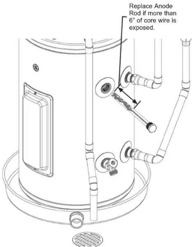
Anode Rod
Anode rods are designed and installed to protect and extend the life of residential water storage tanks.
The anode rod must be removed from the water heater's tank and inspected annually, and replaced when more than 6" (15.2 cm) of core wire is exposed at either end of the rod.* NOTE: Artificially softened water will cause the anode rod to consume more rapidly.
Due to shock hazard and to prevent accidental water leaks, this inspection should be done by a qualified servicer or plumber, and requires that the electric power and cold water supply be turned off before servicing the anode rod.
NOTICE: Do not remove the anode rod from the water heater's tank except for inspection and/or replacement, as operation with the anode rod removed will shorten the life of the glass-lined tank and will void warranty coverage.
*NOTE: Failure to replace the anode rod when consumed voids the warranty for the tank. Warranty coverage for all other components remains intact, and is unaffected by this maintenance requirement. The replacement anode rod, and the inspection for consumption are not covered by warranty.
CAUTION - IMPORTANT SAFETY NOTICE
This information is intended for use by individuals possessing adequate background of electrical, electronic and mechanical experience. Any attempt to repair a major appliance may result in personal injury and property damage. The manufacturer or seller cannot be responsible for the interpretation of this information, nor can it assume any liability in connection with its use.
Tools needed:
- Socket/Torque Wrench
- 1 1/16" Socket
- Pipe Joint Compound or Pipe Thread Sealant Tape
- Anode Rod, if needed
- See page 18 for part ordering instructions
To Service Anode Rod:
- Disconnect power, shut off the water supply, drain the water lines of the home. Drain the water heater through the lower drain valve.
- Using a 1 1/16" socket, unscrew the anode rod, then lift out to inspect.
- Inspect and replace if necessary.
- To install the anode rod, seal the threads with pipe joint compound or pipe thread sealant tape, thread into the port tighten.
- Turn water supply on, open a tap to remove any air in plumbing system, fill water heater with water, inspect for leaks, then turn the power on. NOTE: Do not turn on power until water heater is completely filled.
Installation Instructions
The location chosen for the water heater must take into consideration the following:
LOCAL INSTALLATION REGULATIONS
This water heater must be installed in accordance with these instructions, local codes, utility codes, utility company requirements or, in the absence of local codes, the latest edition of the National Electrical Code. It is available from some local libraries or can be purchased from the National Fire Prevention Association, Batterymarch park, Quincy, MA 02169 as booklet ANSI/NFPA 70.
POWER REQUIREMENTS
Check the markings on the rating plate of the water heater to be certain the power supply corresponds to the water heater requirements.
LOCATION
The water heater and water lines should be protected from freezing temperatures and high-corrosive atmospheres. Do not install the water heater in outdoor, unprotected areas.
Locate the water heater in a clean dry area as near as practical to the area of greatest heated water demand. Long uninsulated hot water lines can waste energy and water. Unit must be installed in a level location. If required, add shims under base of unit to level for proper operation.
NOTE: This unit is designed for any common indoor installation.
Servicing the water heater requires proper installation such that front panels can be removed to permit inspection and servicing. Reference installation instructions found in this manual.
Moving the water heater or other appliances to provide service to the water heater is not covered under warranty.
CAUTION
Risk of Property Damage -
The water heater should not be located in an area where leakage of the tank or connections will result in damage to the area adjacent to it or to lower floors of the structure. Where such areas cannot be avoided, it is recommended that a suitable catch pan, adequately drained, be installed under the water heater.
LOCATION (Cont).
Required clearances:
There must be sufficient clearance between any object and the top, rear and sides of the water heater in the event service is needed. The controls and drain at front of unit must have clear access for operation and service. Installations that require minimal clearance on the sides or rear of the water heater for earthquake straps are also acceptable. In these cases, additional clearance should be provided on the opposite side of the unit to allow for service access.
CATCH PAN INSTALLATION (If required)
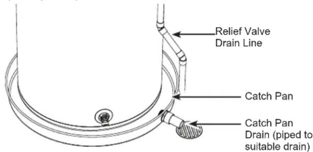
NOTE: Auxiliary catch pan MUST conform to local codes. Catch Pan Kits are available from the store where the water heater was purchased, a builder store or any water heater distributor. The catch pan should be 2^ (5.1 cm) minimum larger than the Water Heater base diameter. To prevent corrosion and improve Drain Valve access it is recommended that the water heater be placed on spacers inside the catch pan.
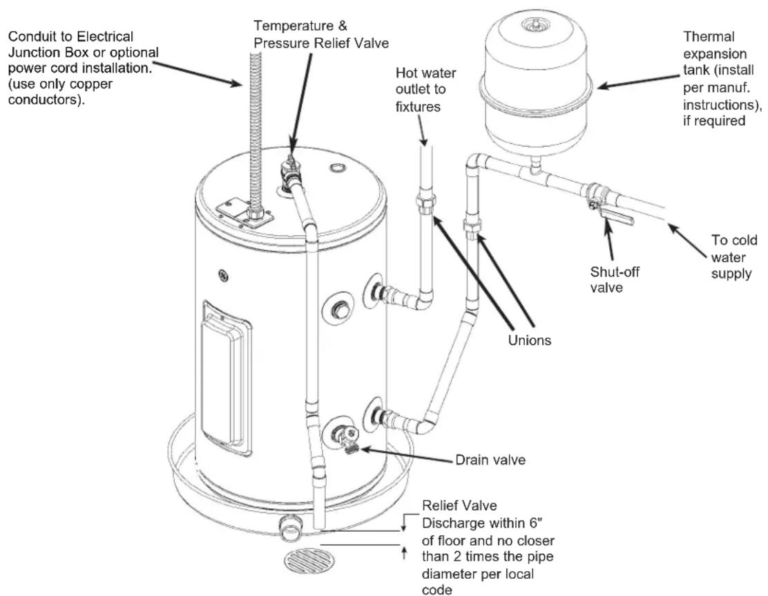
THERMAL EXPANSION
If a check valve is present on the inlet water line, it will create a "closed system." Heating water in a closed system creates an increase in pressure within the water system because the pressure is not able to dissipate in the main supply line. Referred to as "thermal expansion", the rapid pressure increase can cause the relief valve to operate (releasing water) during each heating cycle, potentially causing premature failure to the valve or even the water heater. The suggested method of controlling thermal expansion is to install an expansion tank in the cold water line between the water heater and the check valve as shown in the following illustrations. Contact your installing contractor, water supplier, or plumbing inspector for additional information.
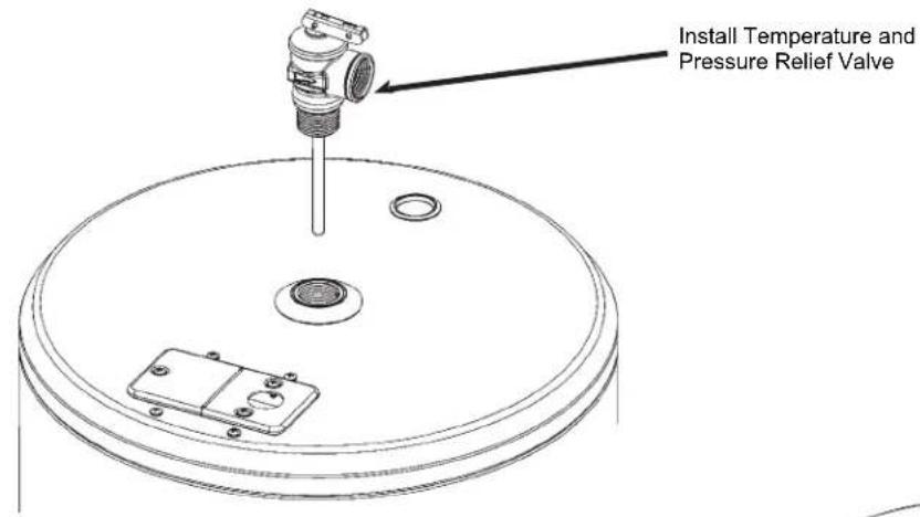
Component Installation
Locate the temperature and pressure relief valve, drain valve, and inlet/outlet fittings in the packaging of your water heater.
Remove and discard all gray colored plugs that were placed in the fitting openings of the water heater for shipping.
Refer to illustrations below for installing each component to the water heater.
After completing installation of all components, make sure to check all connection points for water leaks and correct if required.
Tools needed:
Pipe wrench
- Adjustable wrench
- Pipe joint compound or pip thread sealant tape
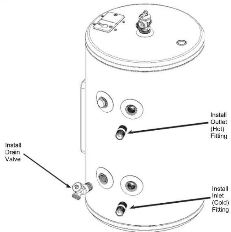
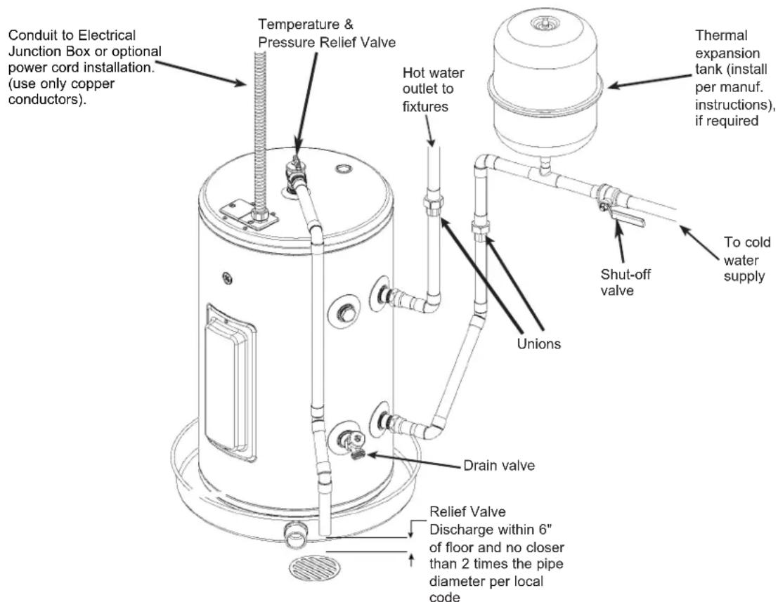
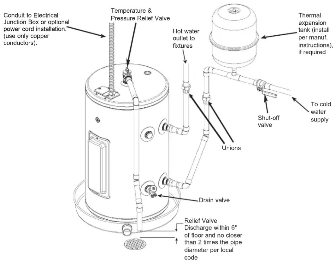
WATER SUPPLY CONNECTIONS
Refer to the illustration below for recommended installation. The HOT and COLD water connections are clearly marked and are 3/4 NPT on all models. When connecting to the inlet/outlet ports, the use of 3/4 female NPT tapered thread fittings with use of thread sealant is recommended. The installation of unions is recommended on the hot and cold water connections so that the water heater may be easily disconnected for servicing if necessary. Piping should be routed to allow anode rod removal.
NOTE: Install a shut-off valve in the cold water line near the water heater. This will enable easier service or maintenance of the unit later.
IMPORTANT: Do not apply heat to the HOT or COLD water connections. If sweat connections are used, sweat tubing to adapter before fitting the adapter to the cold water connections on heater. Any heat applied to the hot or cold water connection will permanently damage the internal plastic lining in these ports.
Install a vacuum relief valve and/or anti-siphon device when required by local jurisdictions.
Typical Installation can be found in the diagram below.
(Model appearance may vary)
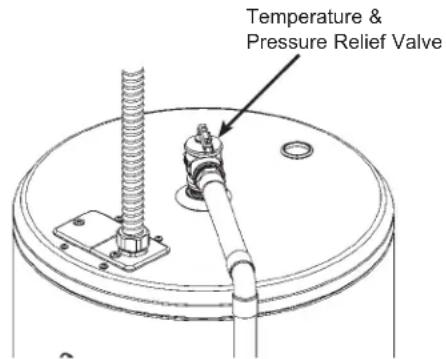
RELIEF VALVE
WARNING Risk of Unit Damage - The pressure rating of the relief valve must not exceed 150 PSI (1.03 MPa), the maximum working pressure of the water heater as marked on the rating plate.
A new combination temperature and pressure-relief valve, complying with the Standard for Relief Valves and Automatic Gas Shut-Off Devices for Hot Water Supply Systems, ANSI Z21.22, is supplied and must remain installed in the opening provided and marked for this purpose on the water heater. No valve of any type should be installed between the relief valve and the tank. Local codes shall govern the installation of relief valves.
The BTUH rating of the relief valve must not be less than the input rating of the water heater as indicated on the rating label located on the front of the heater (1 watt=3.412 BTUH).
Connect the outlet of the relief valve to a suitable open drain so that the discharge water cannot contact live electrical parts or persons and to eliminate potential water damage.
Piping used should be of a type approved for hot water distribution. The discharge line must be no smaller than the outlet of the valve and must pitch downward from the valve to allow complete drainage (by gravity) of the relief valve and discharge line. The end of the discharge line should not be threaded or concealed and should be protected from freezing. No valve of any type, restriction or reducer coupling should be installed in the discharge line.
(Model appearance may vary)
CAUTION
To reduce the risk of excessive pressures and temperatures in this water heater, install temperature and pressure protective equipment required by local codes and no less than a combination temperature and pressure relief valve certified by a nationally recognized testing laboratory that maintains periodic inspection of production of listed equipment or materials, as meeting the requirements for Relief Valves and Automatic Gas Shutoff Devices for Hot Water Supply Systems, ANSI Z21.22. This valve must be marked with a maximum set pressure not to exceed the marked maximum working pressure of the water heater. Install the valve into an opening provided and marked for this purpose in the water heater, and orient it or provide tubing so that any discharge from the valve exits only within 6 inches above, or at any distance below, the structural floor, and does not contact any live electrical part. The discharge opening must not be blocked or reduced in size under any circumstances.
TO FILL THE WATER HEATER
WARNING Risk of Unit Damage - The
tank must be full of water before heater is turned on. The water heater warranty does not cover damage or failure resulting from operation with an empty or partially empty tank.
Make certain the drain valve is completely closed.
Open the shut-off valve in the cold water supply line.
Open each hot water faucet slowly to allow the air to vent from the water heater and piping.
A steady flow of water from the hot water faucet(s) indicates a full water heater.
Condensation can form on the tank and fittings when it is first filled with water. Condensation may also occur with a heavy water draw and very cold inlet water temperature.
This condition is not unusual and will disappear once water is heated. If condition persists, examine fittings for potential leaks and repair, as required.
NOTICE
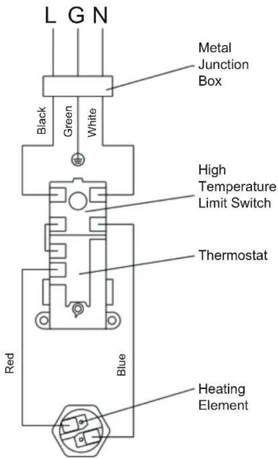
Do not mis-wire electrical connections. 120VAC must be applied to the water heater as shown in "Water Heater Junction Box" illustration.
Installation Instructions
ELECTRICAL CONNECTIONS
IMPORTANT SAFETY INSTRUCTIONS
WARNING
When using electrical appliances, basic safety precautions to reduce the risk of fire, electric
shock, or injury to persons should be followed, including:
- Read all instructions before using this water heater.
- This water heater must be grounded. Connect only to a properly grounded outlet.
- Install or locate this water heater only in accordance with the provided installation instructions.
- Use this water heater only for its intended use as described in this manual.
- Do not use an extension cord set with this water heater. If no receptacle is available adjacent to the water heater, contact a qualified electrician to have one properly installed.
- As with any appliance, close supervision is necessary when used by children.
- Do not operate this water heater if it has a damaged cord or plug, if it is not working properly, or if it has been damaged or dropped.
- This water heater should be serviced only by qualified service personnel. Contact the nearest authorized service facility for examination, repair, or adjustment.
- Do not use surge protectors or multi-outlet adapters with this water heater.
CAUTION
A damaged power supply cord must be replaced with one supplied by the unit manufacturer
and not repaired.
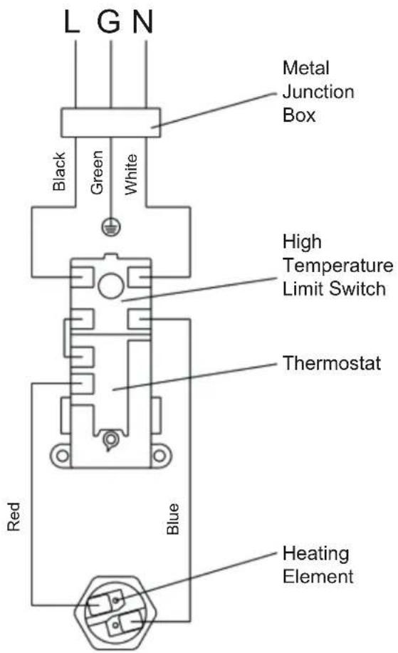
Electrical Connections 120 Volt Supply: GE10P08BA* & GE20P08BA*
A separate branch circuit with copper conductors, overcurrent protective device and suitable disconnecting means must be provided by a qualified electrician.
All wiring must conform to local codes or latest edition of National Electrical Code ANSI/NFPA 70.
The water heater is completely wired to the junction box at the top of the water heater. An opening for 1/2 electrical fitting is provided for field wiring connections.
The voltage requirements and wattage load for the water heater are specified on the rating label on the front of the water heater.
The branch circuit wiring should include either:
- Metallic conduit or metallic sheathed cable approved for use as a grounding conductor and installed with fittings approved for the purpose.
- Nonmetallic sheathed cable, metallic conduit or metallic sheathed cable not approved for use as a ground conductor shall include a separate conductor for grounding. It should be attached to the ground terminals of the water heater and the electrical distribution box.
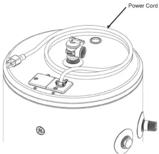
- Factory provided power cord included in the packaging with this water heater.
To connect power to the water heater:
- Turn the power off at circuit breaker.
- Remove the screw/screws holding the junction box top cover.
- Route the electrical wiring through provided strain relief and opening in the junction box cover.
- Install Line to Line, Neutral to Neutral and Ground to Ground, per illustration on this page.
- Reconnect all screws attaching the junction box covers..
WARNING
Risk of fire or electrical shock.
Ensure both junction box covers and ground screws are securely fastened for proper grounding.
NOTE: Install electric connections according to local codes or latest edition of National Electrical Code ANSI/NFPA 70.
WARNING
Proper ground connection is
essential. The presence of water in the piping and water heater does not provide sufficient conduction for a ground. Nonmetallic piping, dielectric unions, flexible connectors, etc., can cause the water heater to be electrically isolated. Do not disconnect factory ground.
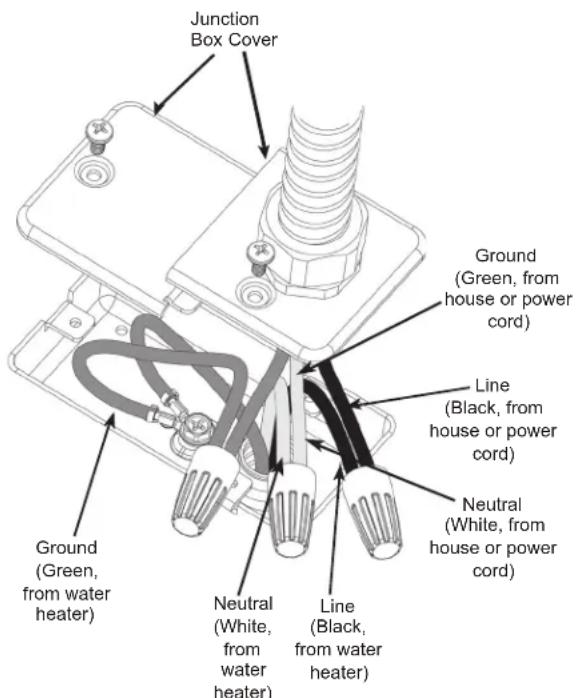
Water Heater Junction Box Illustration
This water heater can be installed in two ways:
- Using a hard wired connection provided by a qualified electrician
- Using the factory provided power cord and plugging into an outlet that has been installed by a qualified electrician (see below illustration for reference)
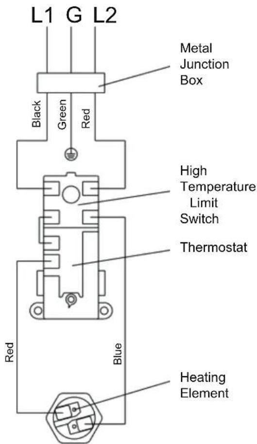
Electrical Connections 240 Volt Supply: GE20L08BA*
A separate branch circuit with copper conductors, overcurrent protective device and suitable disconnecting means must be provided by a qualified electrician.
All wiring must conform to local codes or latest edition of National Electrical Code ANSI/NFPA 70.
The water heater is completely wired to the junction box at the top of the water heater. An opening for 1/2 electrical fitting is provided for field wiring connections.
The voltage requirements and wattage load for the water heater are specified on the rating label on the front of the water heater.
The branch circuit wiring should include either:
- Metallic conduit or metallic sheathed cable approved for use as a grounding conductor and installed with fittings approved for the purpose.
- Nonmetallic sheathed cable, metallic conduit or metallic sheathed cable not approved for use as a ground conductor shall include a separate conductor for grounding. It should be attached to the ground terminals of the water heater and the electrical distribution box.
To connect power to the water heater:
- Turn the power off at circuit breaker.
- Remove the screw/screws holding the junction box top cover.
- Route the electrical wiring through provided strain relief and opening in the junction box cover.
- Install Line to Line, Neutral to Neutral and Ground to Ground, per illustration on this page.
- Reconnect all screws attaching the junction box covers..
WARNING
Risk of fire or electrical shock.
Ensure both junction box covers and ground screws are securely fastened for proper grounding.
NOTE: Install electric connections according to local codes or latest edition of National Electrical Code ANSI/NFPA 70.
WARNING
Proper ground connection is
essential. The presence of water in the piping and water heater does not provide sufficient conduction for a ground. Nonmetallic piping, dielectric unions, flexible connectors, etc., can cause the water heater to be electrically isolated. Do not disconnect factory ground.
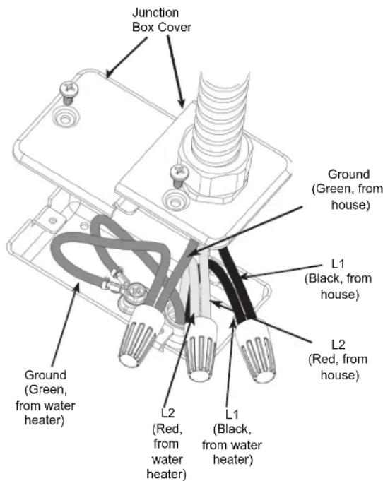
Water Heater Junction Box Illustration
Electrical Connections (cont.)
The manufacturer's warranty does not cover any damage or defect caused by installation, attachment or use of any type of energy-saving or other unapproved devices (other than those authorized by the manufacturer) into, onto or in conjunction with the water heater. The use of unauthorized energy-saving devices may shorten the life of the water heater and may endanger life and property.
The manufacturer disclaims any responsibility for such loss or injury resulting from the use of such unauthorized devices.
If local codes require external application of insulation blanket kits, the manufacturer's instructions included with the kit must be carefully followed.
Application of any external insulation, blankets or water pipe insulation to this water heater will require careful attention to the following:
- Do not cover the temperature and pressure-relief valve.
- Do not cover access panels to the heating elements.
- Do not cover the electrical junction box of the water heater.
- Do not cover the operating or warning labels attached to the water heater or attempt to relocate them on the exterior of the insulation blanket.
BRANCH CIRCUIT SIZING GUIDE
| Total Water Heater Wattage | Recommended Over Current Protection (fuse or circuit breaker amperage rating) | Copper Wire Size AWG Basedon N.E.C. Table 310-16 (167°F/75°C.) | ||||
| 120V 208V | 240V 120V 208V | 240V | ||||
| 1500* 20 15 | 15 12 14 | |||||
| 1700 20 15 | 15 12 14 | |||||
| 2000 25 15 | 15 10 14 | |||||
| 2500 30 15 | 15 10 14 | |||||
| 3000 35 20 | 20 8 12 | |||||
| 3500 - | 25 20 | - | 10 | |||
| 3800 - | 25 20 | - | 10 | |||
| 4000 - | 25 25 | - | 10 | |||
| 4500 - | 30 25 | - | 10 | |||
| 5000 - | 30 30 | - | 10 | |||
| 5500 - | 25 30 | - | 8 | |||
| 6000 - | 40 35 | - | 8 | |||
| 9000 - | 50 | - | - | |||
*Less than 1500 Watts may be wired 14 gauge with 15 amp protection. Check local electrical codes, as they will also apply.
NOTE: This guide recommends minimum branch circuit sizing based on the National Electric Code. Refer to wiring diagrams in this manual for field wiring connections.
Troubleshooting
Before you call for service....
Save time and money! Review the chart below first and you may not need to call for service.
CAUTION
For your safety, DO NOT attempt repair of electrical wiring, controls, heating elements or other
safety devices. Refer repairs to qualified service personnel.
| Problem Possible Causes What To do | ||
| OPERATION AND PERFORMANCE | ||
| Not enough or no hot water | Water temperature may be set too low | See the Water Temperature Adjustment and Water Heater Capacity sections (see pages 4 and 6). |
| Cold water inlet temperature may be colder during the winter months | This is normal. The colder inlet water takes longer to heat. Consider increasing the set temperature as described in the Water Temperature Adjustment section. | |
| Leaking or open hot water faucets | Make sure all faucets are closed. | |
| Long runs of exposed pipe, or hot water piping on outside wall | Insulate piping. | |
| Dip tube damaged | Contact your local installer, plumbing contractor, or previously agreed upon service agency. | |
| A fuse is blown, circuit breaker tripped, or electric service to your home may be interrupted | Replace fuse or reset circuit breaker. Contact the local electric utility. | |
| Inadequate wiring | See the Installation Instructions. | |
| Manual reset high limit (ECO) | See the Safety Controls section, see page 5. | |
| Water Connections to unit reversed | Correct piping connections. | |
| Water is too hot Water temperature is set too high | See the Water Temperature Adjustment section. | |
| Thermostat has failed | Contact your local installer, plumbing contractor, or previously agreed upon service agency. | |
| OTHER | ||
| Rumbling noise Water conditions in your home caused a buildup of scale or mineral deposits on the heating elements | Remove and clean the heating elements. This should only be done by a qualified service person or plumbing contractor. | |
| Water dripping down the outside of the heater | Hot/Cold water connections or other parts have loosened | Tighten the loose connections. This should only be done by a qualified service person or plumbing contractor. |
| Relief valve producing popping sound or draining | Pressure buildup caused by thermal expansion to a closed system | This is an unacceptable condition and must be corrected. See Thermal Expansion section on page 14. Do not plug the relief valve outlet. Contact a plumbing contractor to correct this. |
| Hot water has a rotten egg or sulfur smell | Certain water supplies with high sulfate content will react with the anode rod that is present in all water heaters for corrosion protection of the tank | In certain cases, increasing the tank temperature to 140°F (60°C) can reduce this odor issue. Reference the Water Temperature Adjustment section of the Important Safety Information of this manual for procedure and dangers of scalding water. Installation of temperature limiting valves can be used to reduce risk of scalding. |
Replacement Parts
For GE Branded Thermostat Control Point of Use Electric Water Heater Models.
Instructions for Placing a Parts Order
To place orders using a Visa/MasterCard or Discover contact GEApplianceparts.com.
All parts orders should include:
- The model and serial number of the water heater from the rating plate.
- Specify voltage and wattage as marked on the rating plate.
- Part description (as noted below) and number of parts desired.
CAUTION For your safety, DO NOT attempt repair of electrical wiring, thermostat(s), heating elements or other operating controls. Refer repairs to qualified service personnel.
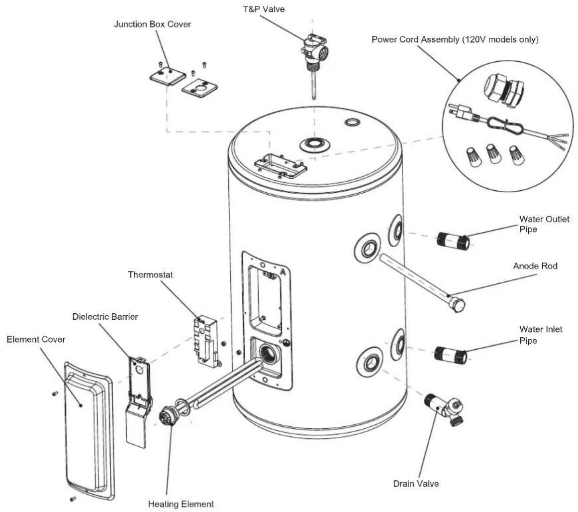
Appearance may vary by model.
120 Volt Supply:
GE10P08BA*
GE20P08BA*
240 Volt Supply:
GE20L08BA*
GE Appliances Electric Water Heater Limited Warranty
All warranty service is provided by our Factory Service Centers, or an authorized Customer Care® technician. To schedule service for your GE water heater call GE Water Heaters at 1-800-943-8186. Please have your serial number and your model number available when calling for service. Servicing your appliance may require the use of the onboard data port for diagnostics. This gives a GE Appliances factory service technician the ability to quickly diagnose any issues with your appliance and helps GE Appliances improve its products by providing GE Appliances with information on your appliance. If you do not want your appliance data to be sent to GE Appliances, please advise your technician not to submit the data to GE Appliances at the time of service
| For The Period Of: We Will | Replace: |
| One Year From the date of the original purchase, if used in residential home | Any factory specified part of the water heater which fails due to a defect in materials or workmanship. During this limited one-year warranty, we will also provide, free of charge, all labor and related service to replace the defective part. |
| Second through Eighth Year From the date of the original purchase if used in residential home | Any part of the Water Heater which fails due to a defect in materials or workmanship. During this warranty period, labor and related service to replace the defective part are not included. |
| One Year From the date of the original purchase, if used in residential vehicle |
What Is Not Covered:
Service trips to your home to teach you how to use the product.
Improper installation, delivery or maintenance.
- Replacement parts shipping and handling and cost to remove defective part or tank after the first year limited warranty are NOT covered.
Failure of the product if it is abused, misused, altered, or used for other than the intended purpose.
Use of this product where water is microbiologically unsafe or of unknown quality, without adequate disinfection before or after the system.
Replacement of house fuses or resetting of circuit breakers.
- Damage to the product caused by accident, lightning, fire, flood or acts of God.
- Incidental or consequential damage caused by possible defects with this appliance, its installation or repair.
Product not accessible to provide required servicen a safe manner. Attic installation must have flooring and accessible stairs.
If product removed from original installation location.
If product or other appliance must be moved for service access.
- Damage, malfunction or failure caused by the use of repair service not approved by GE Appliances.
- Damage, malfunction or failure caused by the use of unapproved parts or components.
- Damage, malfunction or failure caused by operating the water heater with the anode rod removed.
Anode Rod inspection and replacement. - Damage, malfunction or failure resulting from operating the water heater with an empty or partially empty tank.
- Damage, malfunction or failure caused by subjecting the tank to pressure greater than those shown on the rating label.
- Damage, malfunction or failure caused by operating the water heater with electrical voltage outside the voltage range listed on the rating label.
Water heater failure due to the water heater being operated in a corrosive atmosphere.
If this water heater is used for other than private family use, labor will not be covered under warranty, and the parts warranty is reduced to 1 year from the date of purchase.
EXCLUSION OF IMPLIED WARRANTY--Your sole and exclusive remedy is product repair as provided in this Limited Warranty. Any implied warranties, including the implied warranties of merchantability or fitness for a particular purpose, are limited to one year or the shortest period allowed by law.
This limited warranty is extended to the original purchaser and any succeeding owner for products purchased within the USA. If the product is located in an area where service by a GE Appliances Authorized Servicer is not available, you may be responsible for a trip charge or you may be required to bring the product to an Authorized GE Appliances Service location for service. In Alaska, the limited warranty excludes the cost of shipping or service calls to your home.
Some states do not allow the exclusion or limitation of incidental or consequential damages. This limited warranty gives you specific legal rights, and you may also have other rights which vary from state to state. To know what your legal rights are, consult your local or state consumer affairs office or your state's Attorney General.
For product purchased outside of the US, contact your dealer for Warranty and Service information.
Warrantor for Products Purchased in the United States:
GE Appliances, a Haier company
Louisville, KY 40225
Consumer Support
Register Your Appliance
Register your new appliance on-line at your convenience! Timely product registration will allow for enhanced communication and prompt service under the terms of your warranty, should the need arise.
- Scan QR Code on product registration card, or on product.

NOTE: This is just an example of what a QR code represents.
- Or go to GEAppliances.com/register
- Or mail in your pre-printed registration card included in the packing material
Consumer Service
If you have a question or need assistance with your new water heater on adjustments, repairs, or routine maintenance:
- Review the Troubleshooting Tips or Care and Cleaning sections of this Owner's Manual.
- Contact your local installer, plumbing contractor, or call GE Appliances Service and Support at 1-800-943-8186.
NOTE: Your installer phone number may be located on the product label.
If you still have issues, contact the GEA Customer Support at GEAppliances.com/waterheater
Parts and Accessories
Individuals qualified to service their own appliances can have parts or accessories sent directly to their homes. (VISA, MasterCard and Discover cards are accepted). Order on-line today 24 hours every day.
In the US, go to GEApplianceparts.com
Contact Us
If you are ultimately not satisfied with the service you receive, contact us on our Website with all the details including your phone number, or write to:
In the US: General Manager, Customer Relations |GE Appliances, Appliance Park |Louisville, KY 40225
GEAppliances.com/contact
Certified to NSF/ANSI 372
Voir http://info.nsf.org/Certified/LeadContent/ for specific model listing
NOUS VOUS REMERCIONS D'ACCUEILLIR GE APPLIANCES CHEZ VOUS
Instructions d-installation
(Model appearance may vary)
SOUPAPE DE SECURITE
AVERAGEMENT

Water Heater Junction Box Illustration

Water Heater Junction Box Illustration
RACCORDEMENTS ÉLECTRIQUES (cont.)

Appearance may vary by model.
120 Volt Supply:
GE10P08BA*
GE20P08BA*

240 Volt Supply:
GE20L08BA*

What Is Not Covered:
GE Appliances, a Haier company
Louisville, KY 40225
GEAppliances.com/contact

Certified to NSF/ANSI 372

GRACIAS POR HACER QUE GE APPLIANCES SEA PARTE DE SU HOGAR.
(Model appearance may vary)

Water Heater Junction Box Illustration

Water Heater Junction Box Illustration
CONEXIONES ELECTRICAS
Appearance may vary by model.
120 Volt Supply:
GE10P08BA*
GE20P08BA*
240 Volt Supply:
GE20L08BA*

GEAppliances.com/contact

- Electronic Residential
- WATER HEATERS
- OWNER'S MANUAL
- FRANCAIS
- THANK YOU FOR MAKING GE APPLIANCES A PART OF YOUR HOME.
- IMPORTANT SAFETY INFORMATION READ ALL INSTRUCTIONS BEFORE USING THE APPLIANCE
- WARNING
- Safety Precautions
- CAUTION
- FOR INSTALLATIONS IN THE STATE OF CALIFORNIA
- WATER TEMPERATURE ADJUSTMENT
- Time/Temperature Relationship in Scalds
- DANGER
- Water Temperature Setting
- Hotter water
- READ AND SAVE THESE INSTRUCTIONS
- SAFETY CONTROLS
- Operating Instructions
- Water Heater Capacity and Increasing Temperature Setpoint:
- Mixing Valves
- Extended Shutdown Periods
- Exterior Surfaces
- Routine Preventive Maintenance
- Temperature and Pressure-Relief Valve:
- Heating Elements and ECO:
- Draining and Flushing the Water Heater
- Flushing the Tank:
- Routine Preventative Maintenance
- Anode Rod
- CAUTION - IMPORTANT SAFETY NOTICE
- Tools needed:
- To Service Anode Rod:
- Installation Instructions
- LOCAL INSTALLATION REGULATIONS
- POWER REQUIREMENTS
- LOCATION
- LOCATION (Cont).
- Required clearances:
- CATCH PAN INSTALLATION (If required)
- THERMAL EXPANSION
- Component Installation
- WATER SUPPLY CONNECTIONS
- RELIEF VALVE
- TO FILL THE WATER HEATER
- WARNING Risk of Unit Damage - The
- NOTICE
- ELECTRICAL CONNECTIONS
- IMPORTANT SAFETY INSTRUCTIONS
- Electrical Connections 120 Volt Supply: GE10P08BA* & GE20P08BA*
- The branch circuit wiring should include either:
- To connect power to the water heater:
- Electrical Connections 240 Volt Supply: GE20L08BA*
- Electrical Connections (cont.)
- Troubleshooting
- Replacement Parts
- Volt Supply:
- Volt Supply:
- GE Appliances Electric Water Heater Limited Warranty
- What Is Not Covered:
- EXCLUSION OF IMPLIED WARRANTY--Your sole and exclusive remedy is product repair as provided in this Limited Warranty. Any implied warranties, including the implied warranties of merchantability or fitness for a particular purpose, are limited to one year or the shortest period allowed by law.
- Consumer Support
- Register Your Appliance
- Consumer Service
- Parts and Accessories
- Contact Us
- NOUS VOUS REMERCIONS D'ACCUEILLIR GE APPLIANCES CHEZ VOUS
- Instructions d-installation
- SOUPAPE DE SECURITE
- AVERAGEMENT
- RACCORDEMENTS ÉLECTRIQUES (cont.)
- GRACIAS POR HACER QUE GE APPLIANCES SEA PARTE DE SU HOGAR.
- CONEXIONES ELECTRICAS
Brand : GE
Model : GE20L08BAR
Category : Boiler