
WorkWise WWBASEWH - Table Tripp Lite - Free user manual and instructions
Find the device manual for free WorkWise WWBASEWH Tripp Lite in PDF.

| Product Type | Electric Sit-Stand Desk |
| Brand | Tripp Lite |
| Model | WorkWise WWBASEWH |
| Category | Desk |
| Height Range | 60 to 124 cm (without desk top) |
| Base Width | 108 cm (minimum) to 183 cm (maximum) |
| Travel Speed | 3.8 cm per second (no load) |
| Load Capacity | 100 kg (220 lb) |
| Duty Cycle | 10% (2 minutes on, 18 minutes off) |
| Power Supply | 110-120 V |
| LED Display | Yes, with ±2.5 mm increments |
| Number of Presets | 4 |
| Frame Material | Steel |
| Warranty | 5-year limited |
| Certifications | UL 508, UL 1004-7, UL 1004-1, CSA C22.2.14-10, CSA C22.2.100-04, CSA 22.2.77-95 |
| Compliance | ANSI/BIFMA X5.5-2014 |
| Maintenance | Wipe with a damp cloth, avoid liquids |
| Safety | Do not sit on the desk, do not place objects more than 51 cm below, keep children away |
| Intended Use | Dry indoor only, do not use with life support equipment |
Frequently Asked Questions - WorkWise WWBASEWH Tripp Lite
User questions about WorkWise WWBASEWH Tripp Lite
0 question about this device. Answer the ones you know or ask your own.
Ask a new question about this device
Download the instructions for your Table in PDF format for free! Find your manual WorkWise WWBASEWH - Tripp Lite and take your electronic device back in hand. On this page are published all the documents necessary for the use of your device. WorkWise WWBASEWH by Tripp Lite.
USER MANUAL WorkWise WWBASEWH Tripp Lite
Important Safety Instructions 2
Parts List 3
Tools Required 3
Assembly 4
Handset Panel 8
Operation 8
Resetting the Handset 8
Adjusting Desk Height 8
Creating Height Presets 9
Adjusting the LED Display Height 9
Setting the Upper and Lower Limits 9
Troubleshooting 10
Specifications 10
Warranty and Product Registration 11
Español / Français 12
PROTECT YOUR INVESTMENT!
Register your product for quicker service and ultimate peace of mind.
You could also win an ISOBAR6ULTRA surge protector—a \$100 value!
www.tripplite.com/warranty


Manufacturing Excellence.
Important Safety Instructions
SAVE THESE INSTRUCTIONS
This manual contains instructions and warnings that should be followed during the installation, operation, and storage of this product. Failure to heed these instructions and warnings may affect the product warranty.
- Do not sit or stand on the desk frame, and do not crawl or lie under the desk frame.
- Do not place any objects taller than 20 inches underneath the desk.
- Make sure no obstacles are in the desk's path, the desk top is not touching any walls and all cords are appropriate length to accommodate the change in height.
- Keep children away from electric height-adjustable desks, control units and handsets. There is a risk of injury and electric shock.
- This height adjustable desk has electric motors and is designed for use in dry work areas only. Keep all electrical components away from liquids.
- Do not open any of the components (e.g. Legs, Control Box, or Switch); there is a danger of electric shock.
- This product is designed with a duty cycle of 10% (2 minutes on, 18 minutes off).
- In the event of a power outage or if the power cord is unplugged, a manual reset may be necessary (see Operation section for more information).
- The desk height is adjustable so that it can be positioned at the most ergonomically suitable height. Any other use beyond the parameters of proper use or handling as set by the manufacturer is at the user's risk.
- Use of this equipment in life support applications where failure of this equipment can reasonably be expected to cause the failure of the life support equipment or to significantly affect its safety or effectiveness is not recommended.
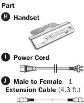
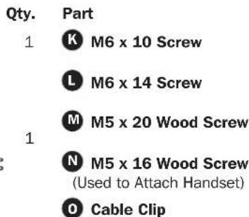
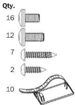
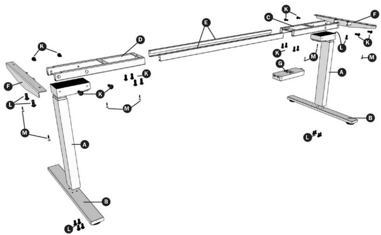
Parts List
| Part | Qty. |
| A Leg | 2 |
| B Foot | 2 |
| C Frame End (Control Box) | 1 |
| D Frame End | 1 |
| E Center Rails | 2 |
| F Side Bracket | 2 |
| G Control Box | 1 |
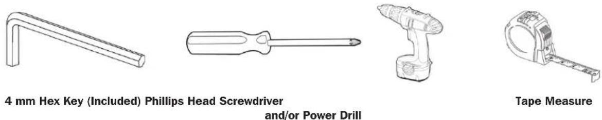
Tools Required
Assembly
Prior to assembly, lay out all components and hardware as listed in the Parts List section.
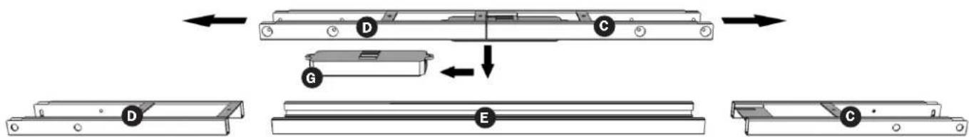
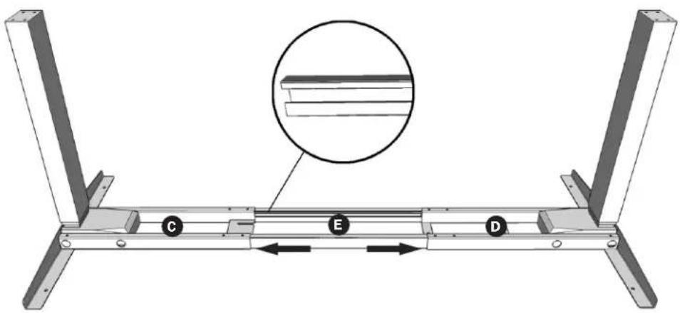
1 Slide the Control Box G off the Frame End Assembly and set aside. Fully separate Frame End D from Frame End (Control Box) C. You will find the Center Rails E inside.
flowchart
graph TD
    A["Component D"] --> B["Component C"]
    B --> C["Component E"]
    C --> D["Component D"]
    C --> E["Component C"]
    style A fill:#f9f,stroke:#333
    style B fill:#ccf,stroke:#333
    style C fill:#cfc,stroke:#333
    style D fill:#fcc,stroke:#333
    style E fill:#cff,stroke:#333
2 Place one of the Legs A into the Frame End (Control Box) C ensuring the bar (arrow) is on "top" in relation to the Leg. Line up the holes on the Leg with the holes on the Frame End (Control Box).
Using the supplied 4 mm Hex Key, insert four (4) M6 x 10 Machine Screws tighten to secure.
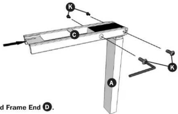
Repeat this step for the other Leg and Frame End D.
3 Slide the Side Bracket F into the Frame End (Control Box) C. Under the Frame End/Leg Assembly, insert two (2) M6 x 14 Screws L. Using the supplied 4 mm Hex Key, tighten screws to secure.
Note: For this step, the Frame End (Control Box) should be placed on the side of the desk where you plan to mount the Control Box and Handset.
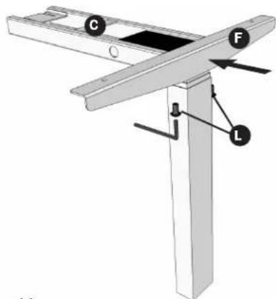
Repeat this step for the other Frame Leg/End Assembly.
Assembly
4 Slide the two (2) Center Rails E into the two Frame Ends C and D. Make sure the slots in the Center Rails face inward and are oriented with the rail's larger lip facing downward (see inset).
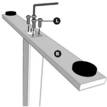
5 For each leg assembly, attach a Foot B with four (4) M6 x 14 Screws L and tighten in a cross-pattern using the supplied 4 mm Hex Key.
natural_image
Diagram of a mechanical setup with labeled parts L and B, no readable text or symbols presentAssembly

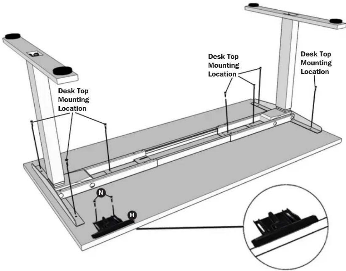
Available separately, WorkWise desk tops include fasteners (10-24 x 5/8" Phillips pan head) and contain preinstalled threaded inserts for easy assembly. Do NOT use power tools to attach the WorkWise desk top to the WorkWise desk base and do NOT overtighten or force supplied screws into the WorkWise desk top's threaded inserts. For non-WorkWise desk tops, fasteners are included M, which may or may not be suitable for installation.

Lay the WorkWise desk top flat so that the threaded inserts are facing upward (the mounting holes on the Side Brackets and Frame Ends should align with the desk top's threaded inserts). Attach the desk base to the desk top using the hardware included with the WorkWise desk top.
Once the desk base is attached to the desk top, align the Handset
the WorkWise desk top. Use two (2) M5 x 16 Wood Screws N
H with the predrilled pilot holes located at the left or right ends of
attach the handset.
Note: For non-WorkWise desk tops, the handset may be placed anywhere along the front edge of the desk top, but it is recommended it be placed toward an end so it does not interfere with the chair when seated.
Assembly
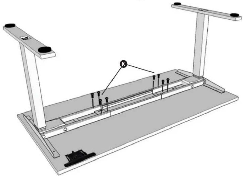
7 Lock the position of the Center Rails using eight (8) M6 x 10 Screws K. Ensure the M6 x 10 Screws contact the Center Rails.
natural_image
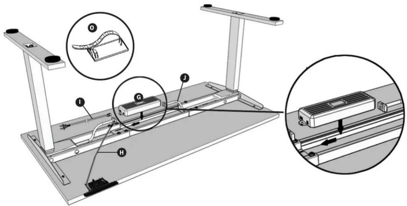
Technical diagram of a mechanical assembly with supports and mounting brackets (no text or symbols)8 Slide the Control Box G into the slots of the Desk Base Assembly.
For the leg closest to the Control Box, insert the leg's male cable connector into the Control Box's nearest female input. For the leg farther away, use the Male to Female Extension Cable ① to establish a connection between the leg's male cable connector and the female input found on the Control Box's other end.
Connect the Handset H cable to the Control Box.
Connect the Power Cord 1 to the Control Box.
To prevent cable sag, secure cables using the adhesive-backed Cable Clips
Assembly
9 Using an assistant or mechanical lifting equipment, grasp the Desk Base Assembly (do NOT lift the desk top) and turn the desk right-side up. Adjust the preinstalled leveling feet to stabilize the desk on uneven floor surfaces.
When lifting or moving the desk, do not lift from the desktop; always lift the desk from the WorkWise desk base.
10 Plug the Power Cord into a 110-120V power outlet.
Handset Panel
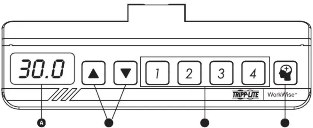
A LED Display: Measures desk height in ±0.1 inch increments.
B Up/Down Buttons: Adjusts desk to the desired height.
C Height Preset Buttons: Automatically adjusts desk to a custom configured height.
D Memory Button: Used to set height presets.
Operation

Prior to operating, make sure no obstacles are in the desk's path, the desk top is not touching any walls, and all cords are appropriate length to accommodate the change in height.
Resetting the Handset
IMPORTANT: The desk's Handset must be RESET prior to first use.
To reset the Handset, press and hold the DOWN button until the desk reaches its lowest height.
Release the DOWN button. Then press and hold the DOWN button again until the LED display reads "RST". Again release the DOWN button. Once more, press and hold the DOWN button until the desk lowers a little bit more, slightly rises and stops. Release the DOWN button one final time. The Handset has been properly reset and the desk is now ready to use.
Adjusting Desk Height
The desk base can be adjusted by pressing and holding either the UP or DOWN button until the desired height is reached.
Operation
Creating Height Presets
The desk's Handset is programmable for up to four presets. To create a preset, use the UP and DOWN buttons to find a desired height, then press the Button followed by Preset buttons 1 through 4.
CAUTION: Once a preset button is pushed, the desk will move to the programmed height.
Adjusting the LED Display Height
Press the DOWN button on the Handset until the base reaches its lowest position. Measure the height of the base from the floor. If the number on the LED display does NOT match your measurement:
- Press and hold the DOWN button again until the LED display reads "RST".
- Press and hold the button for about 5 seconds. The LED display will flash the starting height.
Note: If the display returns to "RST" before the next step is taken, repeat this step.
To change the starting height values:
| Height Value (in inches) By 0.1 | By 1.0 By 10.0 | ||
| Increase Height Press the UP button | Press the “1” button Press the “3” button | ||
| Decrease Height Press the DOWN | button Press the “2” button Press the “4” button |
Once the new value is displayed, wait about 5 seconds for the display to return to "RST". Finish the reset process by pressing and holding the DOWN button again until the desk lowers a little bit more, slightly rises and stops. Release the DOWN button. The new starting height value is saved and the desk is now ready to use.
Note: The LED display has a ±0.1 inch tolerance.
Setting the Upper and Lower Limits
This base is designed to go to its minimum and maximum heights, allowing for the widest possible range. If changing the settings to a more narrow range is preferred, make sure the power is ON and a number reads in the LED display (if no number appears, please follow the reset procedure described in the Resetting the Handset section).

A reset procedure requires the desk base to fully retract beyond any lower limit set. Always ensure there is proper clearance below the desk base.
To Set the Upper-limit Position:
Use the UP/DOWN buttons to move the base to the desired maximum height position. Make sure the UP button was the last button pushed. Press and hold the 🎨 button until the LED display flashes "S -" once. Then press and release the button two more times in quick succession. The LED display will change to "999" on the third push and automatically return to the selected height. The new upper limit is set.
To Set the Lower-limit Position:
Use the UP/DOWN buttons to move the base to the desired minimum height position. Make sure the DOWN button was the last button pushed. Press and hold the 🧙 button until the LED display flashes "S -" once. Then press and release the button two more times in quick succession. The LED display will change to "000" on the third push and automatically return to the selected height. The new lower limit is set.
To Remove the Upper/Lower-limit Positions:
Use the UP or DOWN button to move the desk to any new position. Press and hold the ⏻ button until the LED display flashes "S -" once. Then press and release the button in succession until the display changes to "555" (ignore any interim readings). After a few seconds, the display will automatically change back to the numbered height position. The upper and lower limits have been removed.
After the upper and lower limits are set, the previous memory positions (1, 2, 3, 4) may be outside the new range of movement. If so, simply reset the memory positions. If attempting to revise a previously set upper or lower limit and it is outside of the existing range, first remove the previously set upper/lower limits.
Troubleshooting
The desk is not functioning properly.
It may need to be reset. Follow the Resetting the Handset procedure outlined in the Operation section.
The Handset LED displays "RST" (reset).
Follow the Resetting the Handset procedure outlined in the Operation section.
The Handset LED displays one of the following error codes:
| Error Code Error summary | ||
| E01 M1 overcurrent protection E08 M2 hall error | ||
| E02 M2 overcurrent protection E09 M3 hall error | ||
| E03 M3 overcurrent protection E10 M4 hall error | ||
| E04 M4 overcurrent protection E11 M5 hall error | ||
| E05 M5 overcurrent protection E12 M6 hall error | ||
| E06 M6 overcurrent protection E13 Communication interrupt between controller A and B | ||
| E07 M1 hall error H01 Overheat protection / Duty cycle protection | ||
To clear the error code, perform the Resetting the Handset procedure outlined in the Operation section. If the error message persists after a reset procedure attempt, contact Tripp Lite support.
The Handset readout displays "HOT".
Allow the base to cool down for 20 minutes.
Specifications
| Height Range | 23.5" to 49" (Without Desk Top) |
| Desk Base Width | 42.5" minimum to 72" maximum |
| Travel Speed | 1.5" per second (No Load) |
| Load Capacity | 220 lbs. @ 20,000 cycles |
| Duty Cycle | 10%. Max. 2 minutes on 18 minutes off |
| Certifications | Tested to UL 508, UL 1004-7, UL 1004-1, CSA C22.2.14-10, CSA C22.2.100-04, CSA 22.2.77-95 |
| Compliance | ANSI/BIFMA X5.5-2014 for Office and Institutional Furnishings |
Warranty and Product Registration
5-Year Limited Warranty
Seller warrants this product, if used in accordance with all applicable instructions, to be free from original defects in material and workmanship for a period of 5 years from the date of initial purchase. If the product should prove defective in material or workmanship within that period, Seller will repair or replace the product, in its sole discretion.
THIS WARRANTY DOES NOT APPLY TO NORMAL WEAR OR TO DAMAGE RESULTING FROM ACCIDENT, MISUSE, ABUSE OR NEGLECT. SELLER MAKES NO EXPRESS WARRANTIES OTHER THAN THE WARRANTY EXPRESSLY SET FORTH HEREIN. EXCEPT TO THE EXTENT PROHIBITED BY APPLICABLE LAW, ALL IMPLIED WARRANTIES, INCLUDING ALL WARRANTIES OF MERCHANTABILITY OR FITNESS, ARE LIMITED IN DURATION TO THE WARRANTY PERIOD SET FORTH ABOVE; AND THIS WARRANTY EXPRESSLY EXCLUDES ALL INCIDENTAL AND CONSEQUENTIAL DAMAGES. (Some states do not allow limitations on how long an implied warranty lasts, and some states do not allow the exclusion or limitation of incidental or consequential damages, so the above limitations or exclusions may not apply to you. This warranty gives you specific legal rights, and you may have other rights which vary from jurisdiction to jurisdiction).
WARNING: The individual user should take care to determine prior to use whether this device is suitable, adequate or safe for the use intended. Since individual applications are subject to great variation, the manufacturer makes no representation or warranty as to the suitability or fitness of these devices for any specific application.
PRODUCT REGISTRATION
Visit www.triplite.com/warranty today to register your new Tripp Lite product. You'll be automatically entered into a drawing for a chance to win a FREE Tripp Lite product!*
* No purchase necessary. Void where prohibited. Some restrictions apply. See website for details.
Regulatory Compliance Identification Numbers
For the purpose of regulatory compliance certifications and identification, your Tripp Lite product has been assigned a unique series number. The series number can be found on the product nameplate label, along with all required approval markings and information. When requesting compliance information for this product, always refer to the series number. The series number should not be confused with the marketing name or model number of the product.
Tripp Lite has a policy of continuous improvement. Specifications are subject to change without notice.


1111 W. 35th Street, Chicago, IL 60609 USA • www.tripplite.com/support
Manufacturing Excellence.
1111 W. 35th Street, Chicago, IL 60609 USA • www.tripplite.com/support
Herramientas Requeridas / Outils requis
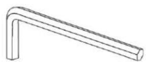
Llave Hex 4 mm (Incluida) / Clé hexagonale de 4 mm (incluse)
natural_image
Diagram of a mechanical setup with labeled parts L and B, no readable text or symbols presentEnsamble / Assemblage

natural_image
Technical line drawing of a mechanical assembly with supports and mounting brackets (no text or symbols)Ensamble / Assemblage

1111 W. 35th Street, Chicago, IL 60609 USA • www.tripplite.com/support