T14438LHD - Faucet DELTA - Free user manual and instructions
Find the device manual for free T14438LHD DELTA in PDF.
| Product Type | Pressure balancing thermostatic valve for tub/shower |
| Brand | Delta |
| Model | T14438LHD |
| Series | 13/14/24 (MultiChoice®) |
| Water supply | Hot and cold water (copper, iron, or PEX connections) |
| Main function | Pressure balancing to maintain stable temperature despite pressure fluctuations |
| Anti-scald limit stop | Adjustable to limit maximum water temperature (max 120 °F / 49 °C) |
| Cartridge | Interchangeable (depending on manufacturing date: RP19804 or RP46074 or RP74236) |
| Body material | Brass |
| Wall installation | For wall thickness up to 1 in (standard); optional kit for thick walls up to 1 3/4 in |
| Tub spout connection | 1/2 in (13 mm) min copper pipe, straight, length 8-18 in (203-457 mm), single 90° elbow |
| Maintenance and cleaning | Clean with a soft damp cloth; avoid abrasive products and cleaners like Scrubbing Bubbles® or Lysol® on clear handles |
| Common replacement parts | Seat and spring kit RP4993, O-ring RP14414, cartridge RP46074 |
| Warranty | Limited lifetime warranty for first residential owner; 10 years for multi-family applications; 5 years for other commercial uses |
| Safety | Do not install a shut-off device on an outlet; do not use PEX tubing for the spout |
Frequently Asked Questions - T14438LHD DELTA
User questions about T14438LHD DELTA
0 question about this device. Answer the ones you know or ask your own.
Ask a new question about this device
Download the instructions for your Faucet in PDF format for free! Find your manual T14438LHD - DELTA and take your electronic device back in hand. On this page are published all the documents necessary for the use of your device. T14438LHD by DELTA.
USER MANUAL T14438LHD DELTA
To reduce the risk of injury due to hot water burns, make sure the enclosed labels are applied where specified on the label.
DOCUMENTOS IMPORTANTES INCLUIDOS AVISO:
NOTICE TO INSTALLER: Place this label on the water heater next to the temperature adjustment knob.
WARNING:
These series of tub/shower valves do not adjust automatically for changes in temperature at the hot water heater or inlet. If the temperature setting of the hot water heater or inlet is changed, the setting on these valves must be adjusted manually! Failure to re-adjust the valve may result in hot water burns or extreme cold resulting from variations in line pressure (such as when a dishwasher or washing machine is in use while you are taking a shower). After installation, verify that the rotational limit stop or temperature knob on the valve is set so that changes in line pressure or temperature do not result in uncomfortable water temperature changes. If the temperature setting of the hot water heater or inlet is changed after installation of the valve, the setting of the rotational limit stop or temperature knob also must be changed! Consult the installation instruction sheet for instructions on how to make this setting, or call us at 1-800-345-DELTA.
NOTICE TO INSTALLER: Place this label close to the valve where the owner will see it, such as inside the door of a cabinet or vanity.
WARNING
Water temperature changes due to seasonal or other inlet variations, such as changing the setting on the hot water heater may require adjustment of the rotational limit stop or temperature knob on your tub/shower valve to ensure a safe maximum temperature. These valve series do not automatically adjust for inlet temperature changes. If changes occur and you are not sure how to make the necessary rotational limit stop or temperature knob adjustments, please consult the installation instruction sheet provided with this valve or call 1-800-345-DELTA. These valve series are designed to minimize the effects of outlet water temperature changes due to inlet pressure changes, commonly caused by dishwashers, washing machines, toilets and the like. They may not provide protection from hot water burns when there is a failure of other temperature controlling devices elsewhere in the plumbing system. After making the necessary adjustments please fill in the information below. This valve/system has been set by the person listed below to ensure a safe maximum temperature. Any change in the setting may raise the discharge temperature above the limit considered safe and could lead to hot water burns. If this label has not been completed, you should verify that the rotational limit stop or temperature knob has been properly adjusted to suit your individual installation. The installation instruction sheet supplied with the valve provides information on how to make this setting.
17 / 27 Series 17T / 27T Series
27T Series
DELTA
Write purchased model number here.

text_image
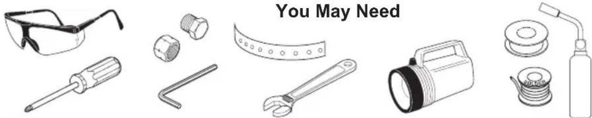
You May NeedTable of Contents:
Warranties ...... Page 2
Installation Instructions....Pages 3 - 12
Clean and care....Page 12
Maintenance......Page 12
Cartridge Summary Reference Sheet ......Page 13
For additional replacement parts,
visit www.deltafaucet.com/service-parts
CAUTION: This system/device must be set by the installer to ensure safe, maximum temperature. Any change in the setting may raise the discharge temperature above the limit considered safe and may lead to hot water burns.
NOTICE TO INSTALLER: CAUTION! – As the installer of this valve, it is your responsibility to properly INSTALL and ADJUST this valve per the instructions given. This valve does not automatically adjust for inlet temperature changes, therefore, someone must make the necessary Rotational Limit Stop adjustments at the time of installation and further adjustments may be necessary due to seasonal water temperature change. YOU MUST inform the owner/user of this requirement by following the instructions. If you or the owner/user are unsure how to properly make these adjustments please refer to page 6 and if still uncertain, call us at 1-800-345-DELTA.
After installation and adjustment, you must affix your name, company name and the date you adjusted the Rotational Limit Stop to the caution
label provided and apply or attach the label to the back side of the closest cabinet door and the warning label to the water heater. Leave this Instruction Sheet for the owner's/user's reference.
WARNING: This pressure balanced or thermostatic bath valve is designed to minimize the effects of outlet water temperature changes due to inlet pressure changes, commonly caused by dishwashers, washing machines, toilets and the like. It may not provide protection from hot water burns when there is a failure of other temperature controlling devices elsewhere in the plumbing system, if the rotational limit stop is not properly set or if the hot water temperature is changed after the settings are made or if the water inlet changes due to seasonal changes.
WARNING: Do not install a shut-off device on either outlet of this valve. When this type of device shuts off the water flow, it can defeat the ability of the valve to balance the hot and cold water pressures.
Limited Warranty on Delta® Faucets
Parts and Finish: All parts (other than electronic parts and batteries) and finishes of Delta ^® faucets purchased from authorized Delta sellers are warranted to the original consumer purchaser to be free from defects in material and workmanship for as long as the original consumer purchaser owns the home in which the faucet was first installed. For commercial purchasers, (a) the warranty period is ten (10) years for multi-family residential applications and (b) five (5) years for all other commercial applications, in each case from the date that the product is received by the original purchaser or their authorized representative (installation contractor, etc.). For purposes of this warranty, the term "multi-family residential application" refers to the purchase of the faucet from an authorized Delta seller by a purchaser who owns but does not live in the residential dwelling in which the faucet is initially installed, such as in a rented or leased single unit or multi-unit detached home (duplex or townhome), or a condominium, apartment building or community living center. The following installations are not considered multi-family residential applications, are excluded from the 10-year warranty and are subject to the 5-year warranty: industrial, institutional or other business premises, such as a dormitory, hospitality premises (hotel, motel or extended stay location), airport, educational facility, long- or short-term healthcare facility (hospital, rehabilitation center, nursing, assisted or staged-care living unit), public space or common area.
Parts and Finish for Delta® Recertified Faucets: Delta Faucet Company offers for sale online Delta® Recertified faucets. Delta® Recertified faucets only include faucets that have been certified as such by Delta Faucet Company. All parts (other than electronic parts and batteries) and finishes of these Delta® Recertified faucets are warranted to the original consumer purchaser to be free from defects in material and workmanship for ten (10) years from the date that the product is received by the original purchaser or their authorized representative (installation contractor, etc.). For commercial purchasers, the warranty period is one (1) year from the date that the product is received by the original purchaser or their authorized representative (installation contractor, etc.).
Electronic Parts: Electronic parts (other than batteries), if any, of Delta faucets purchased from deltafaucet.com or authorized Delta sellers are warranted to the original consumer purchaser to be free from defects in material and workmanship for five (5) years from the date that the product is received by the original purchaser or their authorized representative (installation contractor, etc.) or, for commercial purchasers, for one (1) year from the date that the product is received by the original purchaser or their authorized representative (installation contractor, etc.). No warranty is provided on batteries.
What We Will Do: Delta Faucet Company will repair or replace, free of charge, during the applicable warranty period (as described above), any part or finish that proves defective in material and/or workmanship under normal installation, use and service. Delta Faucet Company may, in its sole discretion, use new, refurbished or recertified parts or products for such repair or replacement. If repair or replacement is not practical, Delta Faucet Company may elect to refund the purchase price in exchange for the return of the product. These are your exclusive remedies.
What Is Not Covered: Because Delta Faucet Company is unable to control the quality of Delta products sold by unauthorized sellers, unless otherwise prohibited by law, this warranty does not cover Delta products purchased from unauthorized sellers.
Any labor charges incurred by the purchaser to repair, replace, install or remove this product are not covered by this warranty. Delta Faucet Company shall not be liable for any damage to the faucet resulting from reasonable wear and tear, outdoor use, misuse (including use of the product for an unintended application), freezing water, abuse, neglect or improper or incorrectly performed installation, maintenance or repair, including failure to follow the applicable care and cleaning instructions. Delta Faucet Company recommends using a professional plumber for all installation and repair of faucets. We also recommend that you use only genuine Delta® replacement parts.
What You Must Do To Obtain Warranty Service or Replacement Parts: A warranty claim may be made and replacement parts may be obtained by calling 1 800 345 DELTA (3358) or by contacting us by mail or online as follows (please include your model number, date of original purchase and documentation of the date of receipt of the product by the original purchaser or their authorized representative (installation contractor, etc.)):
In the United States and Mexico: In Canada:
Delta Faucet Company Masco Canada Limited, Plumbing Group
55 E. 111th Street Technical Service Centre
Carmel, IN 46280 350 South Edgeware Road
Attention: Warranty Service St. Thomas, Ontario, Canada N5P 4L1
www.deltafaucet.com/service-parts/contact-us Attention: Customer Service
http://www.deltafaucet.ca/customersupport/assistance.html
Proof of purchase (original sales receipt showing purchase date) and documentation of the date of receipt of the product by the original purchaser or their authorized representative (installation contractor, etc.) from the original purchaser must be made available to Delta Faucet Company for all warranty claims unless the purchaser has registered the product with Delta Faucet Company or the product is a Delta® Recertified product purchased from deltafaucet.com. This warranty applies only to Delta® faucets manufactured after January 1, 2019 and installed in the United States of America, Canada and Mexico.
Limitation on Duration of Implied Warranties: Please note that some states/provinces (including Quebec) do not allow limitations on how long an implied warranty lasts, so the below limitations may not apply to you. TO THE MAXIMUM EXTENT PERMITTED BY APPLICABLE LAW, ANY IMPLIED WARRANTY, INCLUDING THE IMPLIED WARRANTIES OF MERCHANTABILITY AND OF FITNESS FOR A PARTICULAR PURPOSE, IS LIMITED TO THE STATUTORY PERIOD OR THE DURATION OF THIS WARRANTY, WHICHEVER IS SHORTER.
Limitation of Special, Incidental or Consequential Damages: Please note that some states/provinces (including Quebec) do not allow the exclusion or limitation of special, incidental or consequential damages, so the below limitations and exclusions may not apply to you. TO THE MAXIMUM EXTENT PERMITTED BY APPLICABLE LAW, THIS WARRANTY DOES NOT COVER, AND DELTA FAUCET COMPANY SHALL NOT BE LIABLE FOR, ANY SPECIAL, INCIDENTAL OR CONSEQUENTIAL DAMAGES (INCLUDING LABOR CHARGES TO REPAIR, REPLACE, INSTALL OR REMOVE THIS PRODUCT), WHETHER ARISING OUT OF BREACH OF ANY EXPRESS OR IMPLIED WARRANTY, BREACH OF CONTRACT, TORT, OR OTHERWISE. DELTA FAUCET COMPANY SHALL NOT BE LIABLE FOR ANY DAMAGE TO THE FAUCET RESULTING FROM REASONABLE WEAR AND TEAR, OUTDOOR USE, MISUSE (INCLUDING USE OF THE PRODUCT FOR AN UNINTENDED APPLICATION), FREEZING WATER, ABUSE, NEGLECT OR IMPROPER OR INCORRECTLY PERFORMED INSTALLATION, MAINTENANCE OR REPAIR, INCLUDING FAILURE TO FOLLOW THE APPLICABLE INSTALLATION, CARE AND CLEANING INSTRUCTIONS. Notice to residents of the State of New Jersey: The provisions of this warranty, including its limitations, are intended to apply to the fullest extent permitted by the laws of the State of New Jersey.
Additional Rights: This warranty gives you specific legal rights, and you may also have other rights which vary from state/province to state/province.
This is Delta Faucet Company's exclusive written warranty and the warranty is not transferable.
If you have any questions or concerns regarding our warranty, please contact us as provided above or view our Warranty FAQs at www.deltafaucet.com.
© 2023 Masco Corporation of Indiana
Delta HDF Limited Warranty
All parts of the Delta HDF faucet are warranted to the original consumer purchaser to be free from defects in material and workmanship for a period of five (5) years. This warranty is made to the original consumer purchaser and shall be effective from date of purchase as shown on purchaser's receipt.
Delta will replace, FREE OF CHARGE, during the warranty period, any part which proves defective in material and/or workmanship under normal installation, use and service. Replacement parts can be obtained from your local dealer or distributor listed in the telephone directory or by returning the part along with the purchaser's receipt to our factory, TRANSPORTATION CHARGES PREPAID, at the address listed. THIS WARRANTY IS THE ONLY EXPRESS WARRANTY MADE BY DELTA. ANY CLAIMS MADE UNDER THIS WARRANTY MUST BE MADE DURING THE FIVE YEAR PERIOD REFERRED TO ABOVE. ANY IMPLIED WARRANTIES, INCLUDING THE IMPLIED WARRANTY OF MERCHANTABILITY OR FITNESS FOR A PARTICULAR
PURPOSE, ARE LIMITED IN DURATION TO THE DURATION OF THIS WARRANTY. LABOR CHARGES AND/OR DAMAGE INCURRED IN INSTALLATION, REPAIR OR REPLACEMENT AS WELL AS INCIDENTAL AND CONSEQUENTIAL DAMAGES CONNECTED THEREWITH ARE EXCLUDED AND WILL NOT BE PAID BY DELTA.
Some states do not allow limitations on how long an implied warranty lasts, or the exclusion or limitation of incidental or consequential damages, so the above limitations or exclusions may not apply to you.
This warranty gives you specific legal rights, and you may also have other rights which vary from state to state.
This warranty is void for any damage to this faucet due to misuse, abuse, neglect, accident, improper installation, any use violative of instructions furnished by us or any use of replacement parts other than genuine Delta parts.
© 2022 Delta Faucet Company
1
MultiChoice® Rough-In Installation (When your product requires)
text_image
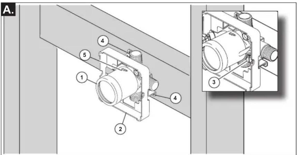
A.SHUT OFF WATER SUPPLIES.
Consider the type and thickness of your finished wall before placing your stringer back plate.
- Install the body (1) so the surface of the finished wall is flush with the front of the plasterguard (2) ± 3/8". Note: For models with stops (3), plasterguard must be flush or subflush 3/8" to
finished wall.
- Mount body using the two stringer mounting holes (4) on the bracket.
- Make sure the word "UP" (5) is on top of the valve body when installing.
text_image
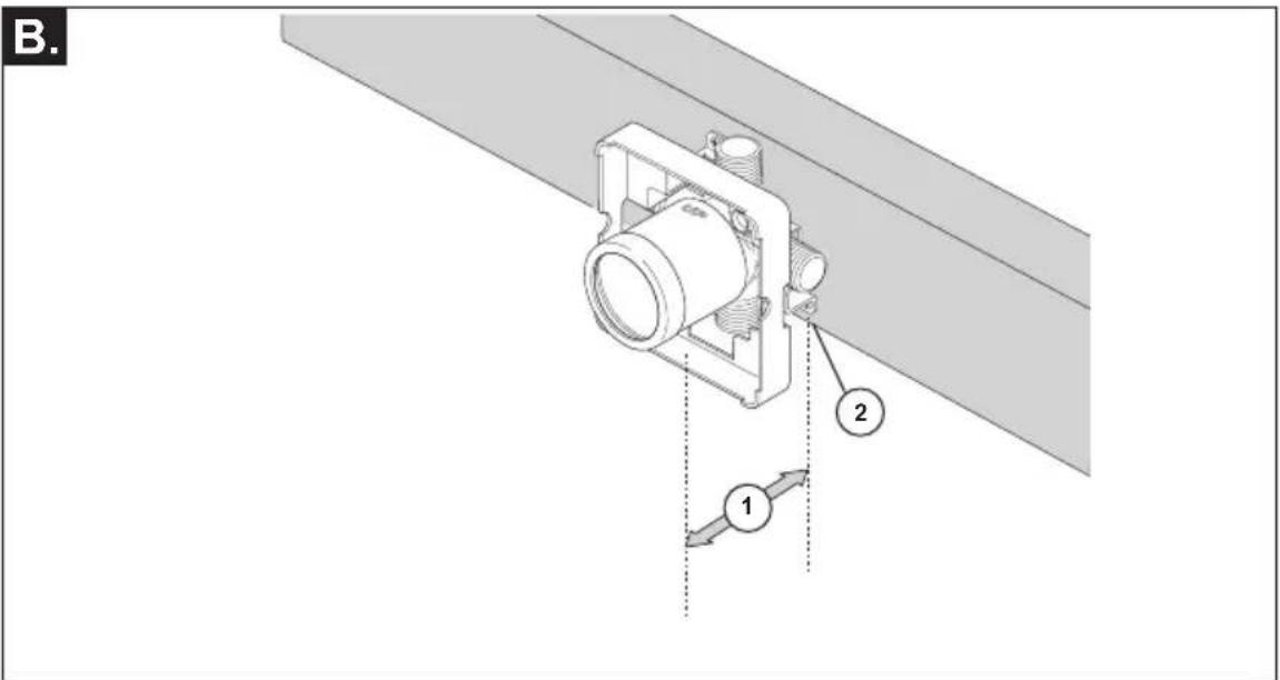
B. 1 2Distance (1) from the stringer (2) to the front of the plasterguard is 2.8" (71 mm).
If a thin wall is used, be sure to have the plasterguard behind the wall, otherwise the wall should always be flush with the front of the plasterguard. See instruction on the bag for thin wall mounting.
text_image
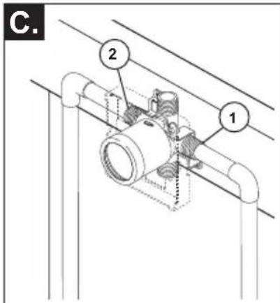
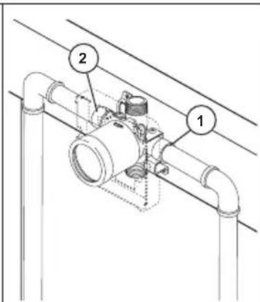
C. 2 1Copper Tubing Iron Pipe
text_image
Technical diagram of a pipe fitting with labeled components 1 and 2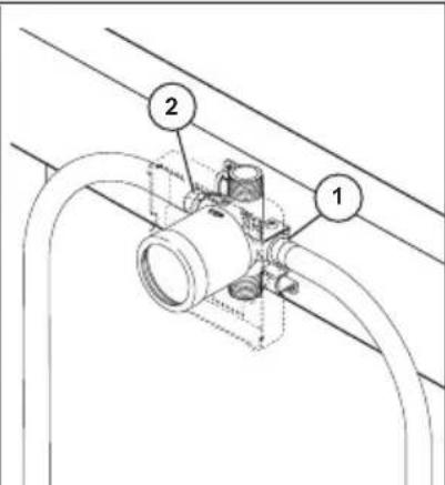
text_image
Technical diagram showing pipe installation with labeled components 1 and 2Pex
- Connect valve body to water supplies using the proper fittings for your valve body type (copper tubing, iron pipe or Pex). Note: (1) is the cold inlet port and (2) is the hot inlet port.
- If either of the two outlet ports is to be unused, seal the port with a pipe plug.
If you are making a BACK TO BACK OR REVERSE INSTALLATION (hot on right and cold on left) install the valve body as described, but the water supply lines will be reversed. Note: (1) is the hot inlet port and (2) is the cold inlet port.
text_image
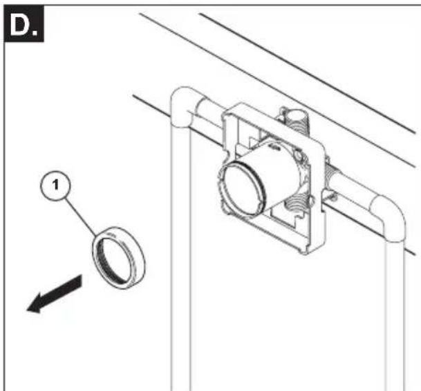
D. 1- Remove bonnet (1). NOTICE: Avoid soldering at high temperatures. Components of the rough could become damaged.
text_image
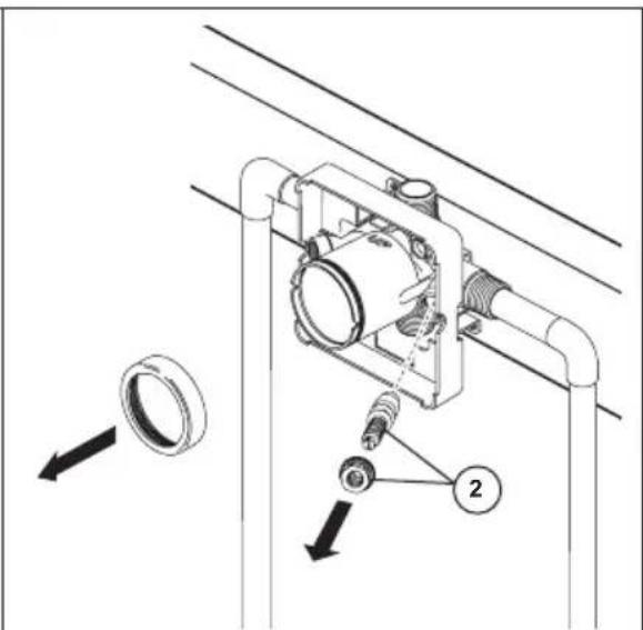
Technical diagram of a mechanical assembly with labeled parts and directional arrows indicating motion or movement.- Be sure stops (2) are removed from the w/stops version before soldering. Do not install stops before soldering.
text_image
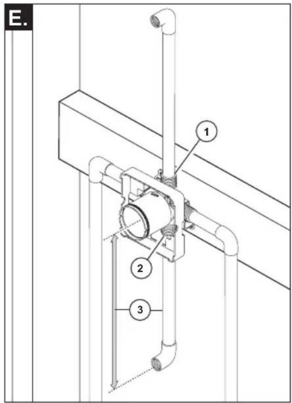
E. 1 2 3- Connect top outlet (1) to shower pipe with proper fittings.
- Connect bottom outlet (2) to tub spout pipe with proper fittings.
- Pipe (3) between valve body and tub spout must be a minimum of 1/2" (13 mm) copper pipe or 1/2" (13 mm) iron pipe in a straight drop no less than 8" (203 mm) but no more than 18" (457 mm) long with only one iron pipe or copper 90 degree elbow to the tub spout nipple. Do not use PEX tubing for tub spout drop.
natural_image
Technical line drawing of a mechanical assembly with a circular component and labeled part (F), no readable text or symbols present.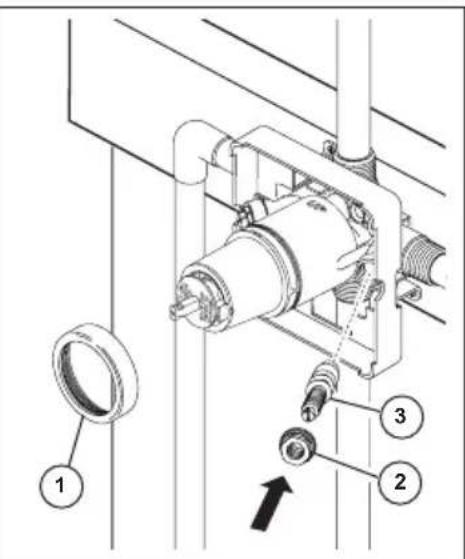
text_image
Technical diagram of a mechanical assembly with numbered components and directional arrow indicating motion or force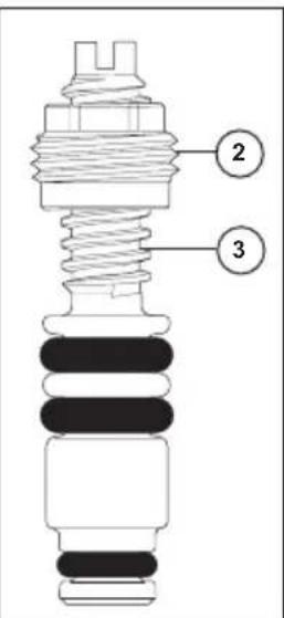
text_image
Technical diagram of an electrical insulator with labeled components 2 and 3PRESSURE TESTING & FLUSHING THE INSTALLATION
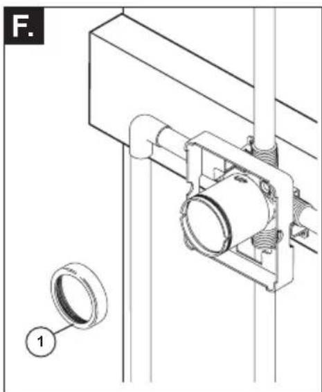
- To flush the system of debris, remove bonnet nut (1).
• Prepare the area for water spray. - Slowly turn on the water supplies to purge the system for 30 seconds.
• After flushing, install the cartridge and bonnet nut. - Turn cartridge stem counter clockwise until it stops.
FOR MODELS WITH STOPS, install the stops but leave them full open. Install stops as follows:
- Thread nut (2) onto stem (3) as shown. Then press stem and nut assembly into body and tighten using a 3/8",6 point, deep well socket. With a flat head screwdriver, adjust stem clockwise to close and counterclockwise to open.
- Plug the tub spout and/or shower outlet(s) with the appropriate fitting for your piping.
- Test for leaks.
• After testing, turn off the valve by rotating the cartridge stem fully clockwise.
2
Cartridge Installation
text_image
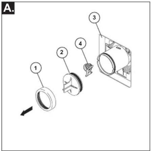
A. 1 2 3 4Turn off water supplies. Remove bonnet nut (1) and test cap (2) from the body. If this is not a thin wall mounting, the entire plasterguard (3) may be removed. If screen (4) is in place, remove before installing cartridge.
text_image
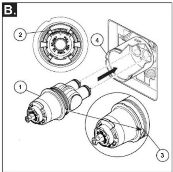
B. 1 2 3 4Rotate valve cartridge (1) so the words "HOTTER COLDER" (2) appear on the top. Insert cartridge assembly into rough-in body. A light coating of plumbers grease applied to o-rings may aid in assembly. Make sure the key (3) on the cartridge is fully engaged with the slot in the brass body (4).
text_image
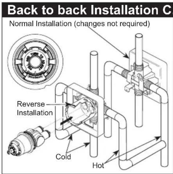
Back to back Installation C. Normal Installation (changes not required) Reverse Installation Cold HotFor back to back or reverse installations (hot on right and cold on left) insert the cartridge with the "hot side" on the right. If you are not making a reverse or back to back installation skip this step and continue with step 2C.
text_image
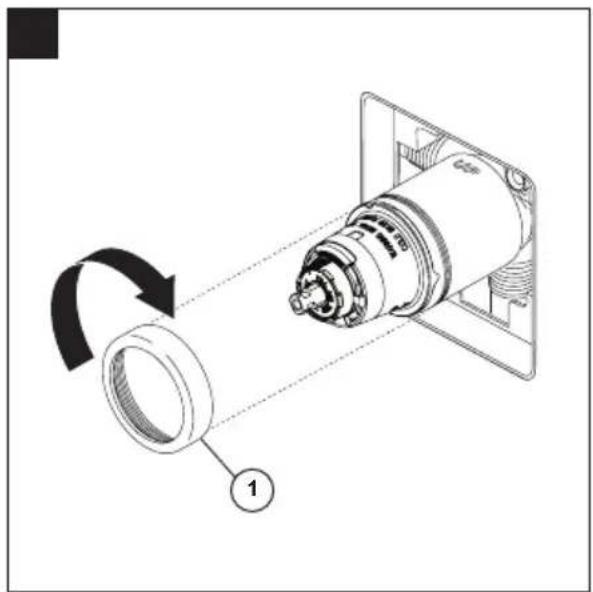
Technical diagram showing a mechanical component with labeled parts and rotation arrow, likely illustrating a mechanical or electrical assembly.Slide bonnet nut (1) over the cartridge and thread onto the body. Hand tighten securely.
3
Shower Head and Tub Spout Installation
text_image
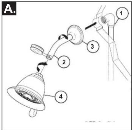
A. 1 2 3 4FOR SHOWER HEAD INSTALLATION: Connect top outlet (1) to shower arm (2) with proper fittings. To prevent damage to finish on shower arm, insert wall end of shower arm into shower flange (3) before screwing arm into riser connection. Thread shower head (4) onto shower arm. Apply plumber tape to pipe threads on both ends. Do not overtighten shower head.
text_image
B-1 1 2 3 4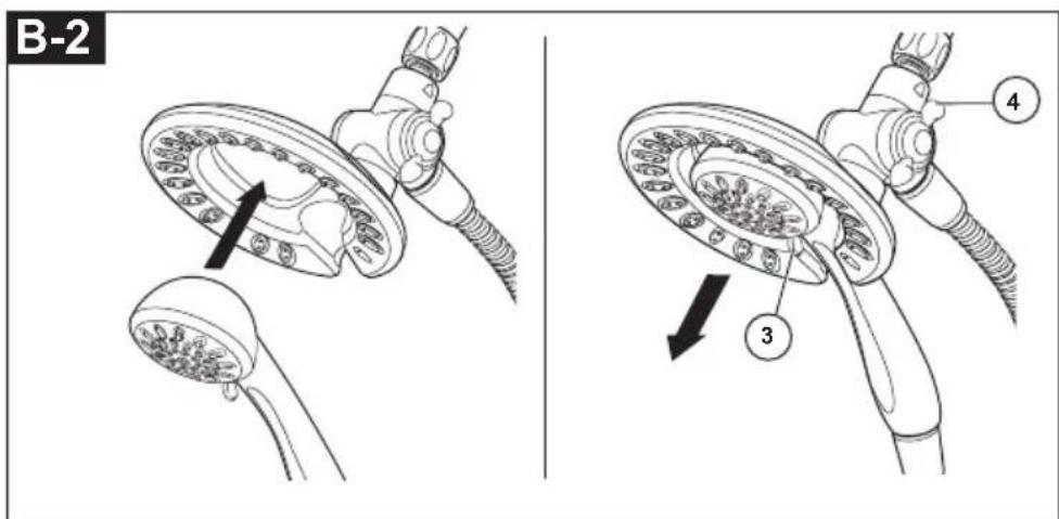
text_image
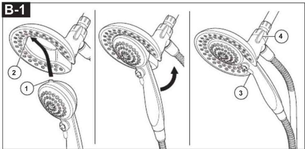
B-2 4 3B-1: To combine the two showers, insert the top tab (1) on the hand shower into the slot (2) of the shower head. Push the hand shower into the shower head until the two parts snap together.
B-2: To combine the two showers, push the hand shower into the shower head, then pull down on the hand shower until locked with the shower head. If the shower head moves when removing the hand shower, hand tighten the connection between the shower head and the shower arm.
To change spray modes, turn the lever (3) left or right to the desired setting. Turn knob (4) to change between shower head only, shower head and hand shower or hand shower only.
FOR TUB SPOUT INSTALLATION:
Refer to the installation instructions supplied with your spout. Do not connect deck mount spouts to in-wall valves. Do not use hand showers connected in lieu of a tub spout to a tub/shower valve. Do not use PEX tubing for tub spout drop.
A-For RLS With Removable Disc
text_image
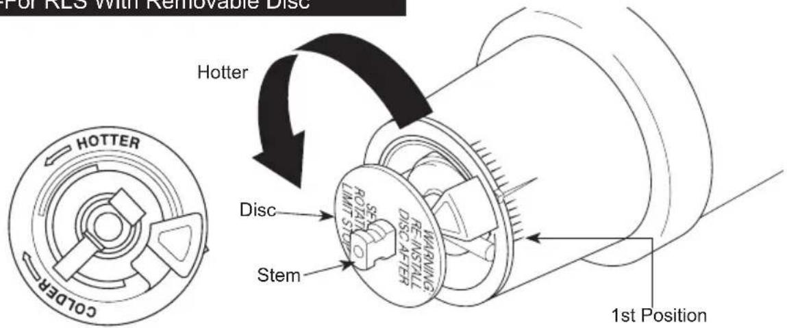
Hotter HOTTER COLOR Disc Stem 1st Position WARNING RE-NSTALL LIMIT ST DISC AFTERIMPORTANT:
The Rotational Limit Stop is used to limit the amount of hot water available such that, if set properly, the user will not be scalded if the handle accidentally is rotated all the way to "hot" when a person is showering or filling a tub. The first position allows the LEAST amount of hot water to mix with the cold water in the system. In the first position the water will be the coldest possible when the handle is turned all the way to hot. As you move the Rotational Limit Stop counterclockwise, you progressively add more and more hot water in the mix. The last position to the left will result in the greatest amount of hot water to the mix, and the greatest risk of scald injury if someone accidentally turns the valve handle all the way to the hot side while showering or filling a tub.
WARNING: In some instances, setting the Rotational Limit Stop in the hottest position (full counterclockwise) could result in scald injury. It is necessary to adjust the Rotational Limit Stop so that the water coming out of the valve will not scald the user when the handle of the valve is rotated to the hot side.
- According to the majority of industry standards, the maximum allowable temperature of the water exiting the valve is 120^ (Your local plumbing codes may require a water temperature less than 120^ ).
- The Rotational Limit Stop may need to be re-adjusted seasonally if the inlet water temperature changes. For example, during the winter, the cold water temperature is colder than it is during the summer which could result in varying outlet temperatures. A water temperature for
a comfortable bath or shower is typically between 90°F - 110°F.
- Run the water so that the cold water is as cold as it will get and hot water is as hot as it will get. Place the handle on the stem (see page 8, step 4C) and rotate the handle counterclockwise until the handle stops.
- Place a thermometer in a plastic tumbler and hold in the water stream. If the water temperature is above 120^ , the Rotational Limit Stop must be repositioned clockwise to decrease valve outlet water temperature to be less than 120^ or to meet the requirements of your local plumbing codes.
- To adjust the temperature of the water coming out of the valve, pull the disc back to a position where it is possible to remove the Rotational Limit Stop and readjust the teeth engagement position to the desired temperature. Clockwise will decrease the outlet temperature, counterclockwise will increase the outlet temperature. Temperature change per tooth (notch) could be 4^ - 16^ based on inlet water conditions. Repeat as necessary. Push disc until fully seated.
WARNING: Failure to re-install Disc after setting Rotational Limit Stop could result in scald injury.
- MAKE SURE COLD WATER FLOWS FROM THE VALVE FIRST. MAKE SURE WATER FLOWING FROM THE VALVE AT THE HOTTEST FLOW POSSIBLE DOES NOT EXCEED 120°F OR THE MAXIMUM ALLOWED BY YOUR LOCAL PLUMBING CODE.
text_image
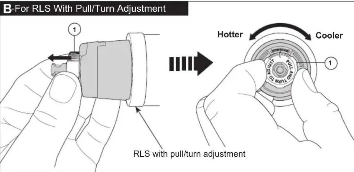
B-For RLS With Pull/Turn Adjustment 1 RLS with pull/turn adjustment Hotter Cooler 1IMPORTANT:
The Rotational Limit Stop is used to limit the amount of hot water available such that, if set properly, a scald injury is less likely to occur if the handle accidentally is rotated all the way to "hot" when a person is showering or filling a tub. The first position allows the LEAST amount of hot water to mix with the cold water in the system. In the first position the water will be the coldest possible when the handle is turned all the way to hot. As you move the Rotational Limit Stop counterclockwise, you progressively add more and more hot water in the mix. The last position to the left will result in the greatest amount of hot water to the mix, and the greatest risk of scald injury if someone accidentally turns the valve handle all the way to the hot side while showering or filling a tub.
WARNING: In some instances, setting the Rotational Limit Stop in the hottest position (full counterclockwise) could result in scald injury. It is necessary to adjust the Rotational Limit Stop so that the water coming out of the valve will not scald the user when the handle of the valve is rotated to the hot side.
- According to the majority of industry standards, the maximum allowable temperature of the water exiting the valve is 120^ (Your local plumbing codes may require a water temperature less than 120^ ).
- The Rotational Limit Stop may need to be re-adjusted seasonally if the inlet water temperature changes. For example, during the winter, the cold water temperature is colder than it is during the summer which could result in varying outlet temperatures. A water temperature for
a comfortable bath or shower is typically between 90°F - 110°F.
- Run the water so that the cold water is as cold as it will get and hot water is as hot as it will get. Place the handle on the stem (see page 8, step 4C) and rotate the handle counterclockwise until the handle stops.
- Place a thermometer in a plastic tumbler and hold in the water stream. If the water temperature is above 120^ , the Rotational Limit Stop must be repositioned clockwise to decrease valve outlet water temperature to be less than 120^ or to meet the requirements of your local plumbing codes.
- To adjust the temperature of the water coming out of the valve, pull the white Rotational Limit Stop (1) outward and rotate. Clockwise rotation will decrease the outlet temperature, counterclockwise rotation will increase the outlet temperature. Temperature change per tooth (notch) could be 4^ - 16^ based on inlet water conditions. Repeat as necessary. When finished, make sure that the Rotational Limit Stop is fully retracted into the seated position. WARNING: Do not take the Rotational Limit Stop apart.
- MAKE SURE COLD WATER FLOWS FROM THE VALVE FIRST. MAKE SURE WATER FLOWING FROM THE VALVE AT THE HOTTEST FLOW POSSIBLE DOES NOT EXCEED 120°F OR THE MAXIMUM ALLOWED BY YOUR LOCAL PLUMBING CODE.
5
Trim Installation
text_image
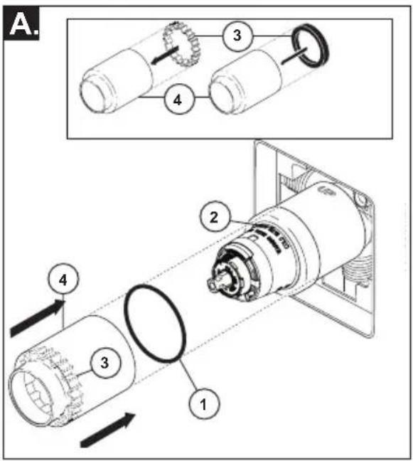
A. 1 2 3 4 5 6 7 8 9 10 11 12 13 14 15 16 17 18 19 20 21 22 23 24 25 26 27 28 29 30 31 32 33 34 35 36 37 38 39 40 41 42 43 44 45 46 47 48 49 50 51 52 53 54 55 56 57 58 59 60 61 62 63 64 65 66 67 68 69 70 71 72 73 74 75 76 77 78 79 80Slide O-ring (1) over cartridge and the bonnet nut (2). The O-ring, which acts as a spacer to steady the sleeve, should rest behind the bonnet nut.
If your model requires a spacer (3), insert it into the sleeve (4) and push it to the front. Slide the sleeve over the cartridge, body and O-ring.
text_image
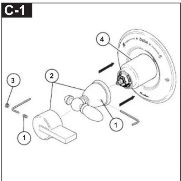
C-1 1 2 3 4Using an Allen wrench to secure the set screw (1), install the handle (2) onto the stem and tighten set screw. Insert plug button (3) (if your model has one) into set screw hole. Adjust the sleeve (4) to minimize the gap between the sleeve & handle.
text_image
B-1 1 2 3 4 5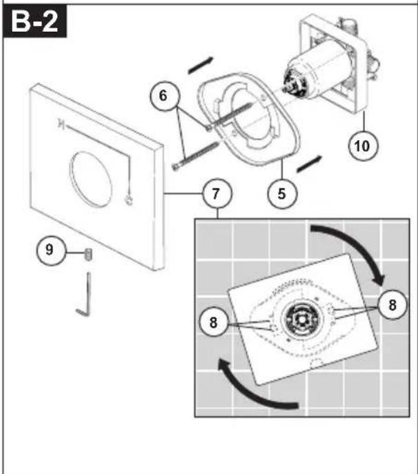
text_image
B-2 6 10 7 5 9 8 8Note: Aduct for up to 1" thick wall. For thick wall installation, visit delta faucet website, check "view technical specification" of the models you bought, order the appropriate thick wall installation kit RP to get additional 1 3/4" wall thickness.
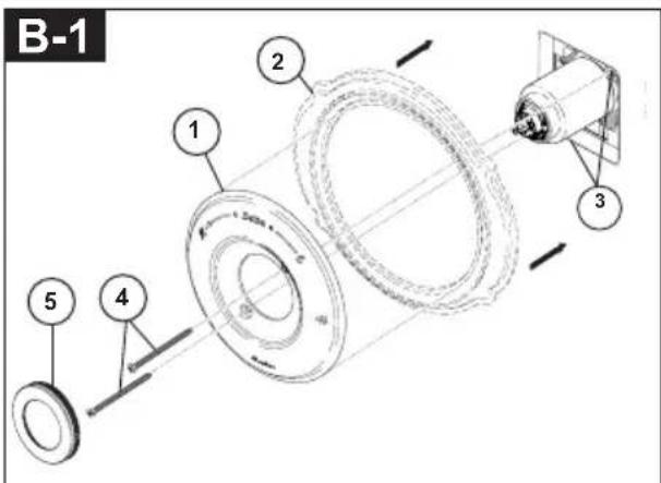
B-1: Secure the escutcheon (1) and backplate (2) (if your model has one) to the bracket (3) using the 2 screws (4) provided. Do not overtighten escutcheon screws. Press the cover (5) onto the escutcheon (1) when your product includes the cover.
B-2: Remove plaster guard (10). Install bracket (5) over the cartridge body using the 2 screws (6) provided. Install escutcheon (7) by placing it over the bracket as shown and rotating it to lock the tabs (8). Secure the escutcheon to the bracket using set screw (9).
text_image
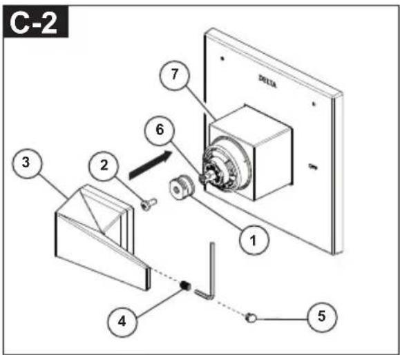
C-2 7 6 3 2 1 4 5Install adapter (1) on cartridge stem (6) with screw (2).
Thread set screw (4) into handle (3) slightly, put handle (3) on adapter (1), hold and adjust the handle (3) at OFF position to ensure it well aligned with sleeve (7). Then tighten set screw (4).
Apply pressure, insert button (5) until properly seated. Adjust the sleeve (7) to minimize the gap between the sleeve & handle.
Clean and Care
Care should be given to the cleaning of this product. Although its finish is extremely durable, it can be damaged by harsh abrasives or polish. To clean, simply wipe gently with a damp cloth and blot dry with a soft towel.
Warning: Scrubbing Bubbles® Bathroom Cleaner and Lysol® Basin Tub and Tile
Cleaner must not be used on the clear knob handles and levers. Use of these cleaners can result in cracked or severely damaged handles. If overspray gets onto the handles, immediately wipe them dry with a soft cotton cloth.
Maintenance
Faucet leaks from tub spout/shower head:
SHUT OFF WATER SUPPLIES.
Replace seats and springs—Repair
Kit RP4993. Check condition of lower O-rings and replace if necessary RP14414. See Helpful Hints 1, 2, & 3.
If leak persists:
SHUT OFF WATER SUPPLIES.
Replace valve cartridge RP46074.
See Helpful Hints 1, 2, 3, 4 & 5
Unable to maintain constant water temperature:
Replace housing assembly with RP46074 or follow instructions in Helpful Hints 1, 2, 3, 4 & 5.
Helpful Hints:
-
Before removing valve cartridge assembly for any maintenance, be sure to note the position of the rotational limit stop on the cap. The valve cartridge assembly must always be put back in the same position. BE SAFE! After you have finished the installation, turn on valve to make sure COLD WATER FLOWS FIRST.
-
To remove valve cartridge from body, shut off
water supplies and remove handle and bonnet nut. Do not pry the valve cartridge out of the body with a screwdriver. Place handle on stem and rotate counterclockwise approximately 1/4 turn after the stop has been contacted. Lift valve cartridge out of body.
- To remove seats and springs.
Remove valve cartridge. Separate cap assembly from the housing assembly by rotating the cap assembly counterclockwise 90 o (degrees). Separate cap and housing assemblies.
- If the water in your area has lime, rust, sand or other contaminants in it, your pressure balance valve will require periodic inspection.
The frequency of the inspection will depend on the amount of contaminants in the water. To inspect valve cartridge remove it and follow the steps in note 1 above. Turn the valve to the full mix position and shake the cartridge vigorously. If there is a rattling sound, the unit is functional and can be reinstalled following instructions given in note 1 above. If there is no rattle, replace the housing assembly with the proper RP.
- Push disc until fully seated. See page 9 for more details
Cartridge Summary Reference Sheet
Monitor® Series 1300/1400
| Cartridge shipped before March 2006. | Cartridge shipped in July 2006 and after (prior to MultiChoice® transition). |
 |  |
| Order RP19804 to replace cartridge. Order RP19804 to replace cartridge. | |
MultiChoice® 13/14
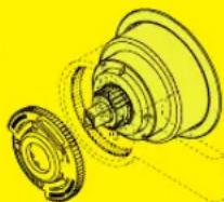
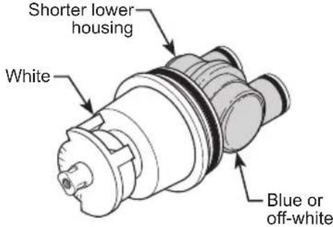
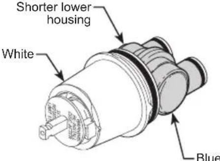
Cartridge shipped from March 2006 to August 2014. Cartridge shipped in August 2014 and after.
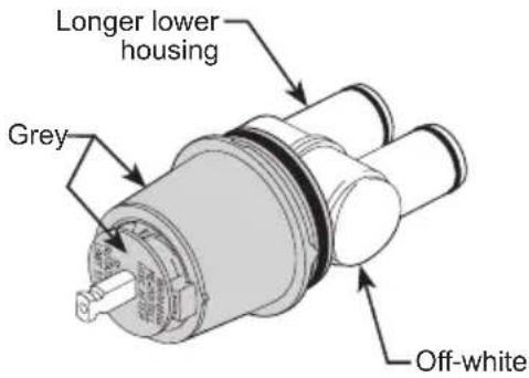
text_image
Longer lower housing Grey Off-white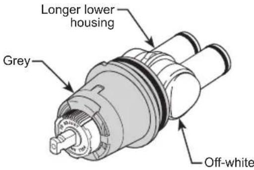
text_image
Longer lower housing Grey Off-whiteOrder RP46074 to replace cartridge. Order RP46074 to replace cartridge.
NOTE: A running change for MultiChoice® 13/14 valves began August 2014, and features a new Rotational Limit Stop.
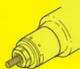
MultiChoice® 13/14 (Ceramic)
Cartridge shipping in select models (-CER).
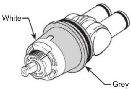
text_image
White GreyOrder RP74236 to replace cartridge.
Delta Faucet Company Masco Canada Limited, Plumbing Group
55 E. 111th Street Technical Service Centre
Camel, IN 46280 350 South Edgeware Road
Attention: Warranty Service St. Thomas, Ontario, Canada N5P 4L1
www.deltafaucet.com/service-parts/contact-us Attention: Customer Service
http://www.deltafaucet.ca/customersupport/assistance.html
© 2022 Delta Faucet Company
text_image
Technical diagram of a mechanical assembly with labeled parts and directional arrows indicating motion or force directions.natural_image
Technical line drawing of a mechanical assembly with a circular component labeled '1' and no visible text or symbols.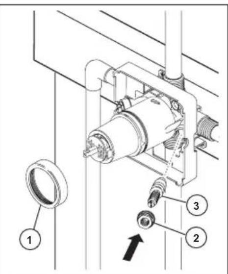
text_image
Technical diagram of a mechanical assembly with numbered components and directional arrow indicating motion or force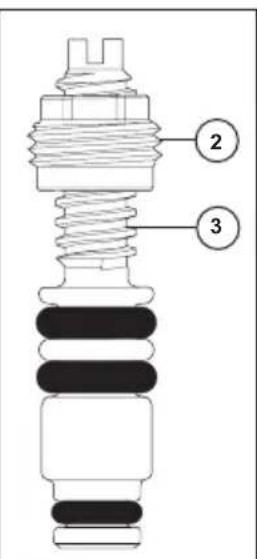
text_image
Technical diagram of an electrical insulator with labeled components 2 and 3text_image
Technical diagram of a mechanical device with numbered components and exploded view, showing internal parts and assembly.text_image
Technical diagram of a mechanical assembly with numbered components and directional arrows indicating motion or movement.Monitor® Series 1300/1400
natural_image
Line drawings of various household cleaning and repair tools including gloves, screwdriver, wrench, lamp, pulley, and spray bottle (no text or labels)Table des matières
Garanties....Page 2
Instructions d'installation ...... Pages 3 - 12
Instructions de nettoyage ......Page 12
Maintenance Page 12
55 E. 111th Street Centre de services techniques
Carmel, IN 46280 350, chemin South Edgeware
Attention: Warranty Service St. Thomas (Ontario) Canada N5P 4L1
www.deltafaucet.com/service-parts/contact-us À l'attention du Service à la clientèle
http://www.deltafaucet.ca/customersupport/assistance.html
text_image
Technical diagram of a pipe fitting with labeled components 1 and 2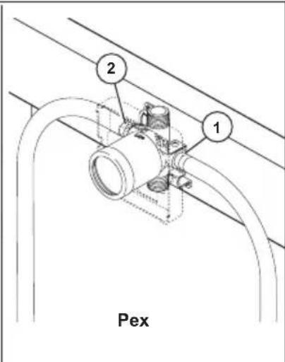
text_image
2 1 Pextext_image
Technical diagram of a mechanical assembly with labeled parts and directional arrows indicating motion or movement.text_image
Technical diagram of a mechanical device with numbered components and exploded view, showing internal structure and assembly.text_image
Technical diagram of a mechanical assembly with numbered components and directional arrows indicating motion or movement.Monitor® Series 1300/1400
see what Delta can do
Delta Faucet Company
Product Service
55 E. 111th Street
Indianapolis, IN 46280