DAC100B6IWDB6 - Air Conditioning DANBY - Free user manual and instructions
Find the device manual for free DAC100B6IWDB6 DANBY in PDF.

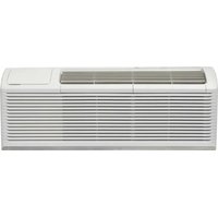
| Product Type | Window Air Conditioner |
| Brand | Danby |
| Model | DAC100B6IWDB6 |
| Cooling Capacity | 10,000 BTU |
| Recommended Area | Up to approximately 30 m² |
| Power Supply | 115 V ~ 60 Hz |
| Approximate Dimensions (W x H x D) | 55.9 x 35 x 48 cm |
| Approximate Net Weight | 30 kg |
| Refrigerant | R32 (Flammable) |
| Operating Modes | Auto, Cool, Dry, Fan |
| Special Features | ECO, Sleep, 24h Timer, Auto Oscillation |
| Remote Control | Yes, with batteries |
| Wireless Connectivity | Yes (WiFi) |
| Air Filter | Washable, monthly cleaning recommended |
| Installation | Double-hung window, width 55.9 to 91.4 cm |
| Safety | Auto shutdown, anti-freeze protection, panel lock |
| Warranty | 2 years functional parts, limited in-home service |
Frequently Asked Questions - DAC100B6IWDB6 DANBY
User questions about DAC100B6IWDB6 DANBY
0 question about this device. Answer the ones you know or ask your own.
Ask a new question about this device
Download the instructions for your Air Conditioning in PDF format for free! Find your manual DAC100B6IWDB6 - DANBY and take your electronic device back in hand. On this page are published all the documents necessary for the use of your device. DAC100B6IWDB6 by DANBY.
USER MANUAL DAC100B6IWDB6 DANBY
Do the right thing.*
OWNER'S MANUAL MANUEL DU PROPRIÉTAIRE MANUAL DEL PROPIETARIO
AIR CONDITIONER
Owner's Manual....1 - 26
CLIMATISEUR
Welcome to the Danby family.
We are proud of our quality products and we believe in dependable service. We suggest that you read this owner's manual before plugging in your new appliance as it contains important operation information, safety information, troubleshooting, and maintenance tips to ensure the reliability and longevity of your appliance.
You are entitled to the warranty coverage as described in the owner's manual provided with your new appliance.
- Please write down your appliance information below. You must keep the original proof of purchase receipt to validate and receive warranty services.
- Register your product online and receive a FREE 2 MONTH WARRANTY EXTENSION after fi lling out a product survey, at www.danby.com/support/product-registration/
Model Number:
Serial Number:
Date of Purchase:
Need Help?
- Read your Owner's Manual for installation help, troubleshooting, and maintenance assistance.
- Visit www.Danby.com to access self-service tools, FAQs and much more by searching your model number in the search bar.
- For the Quickest Customer Service, please fill out the web form at www.danby.com/support. Your submission will go directly to an expert on your particular appliance. Our average response times are between 20 minutes and 2 hours, during EST business hours.
- Call 1-800-263-2629 - please note that during peak hours, hold times can exceed one hour.
 | WARNING Shows that the appliance uses a fl ammable refrigerant. If the refrigerant leaks and is exposed to an external ignition source, there is a risk of fi re. |
 | CAUTION Shows that the operation manual should be read carefully. |
 | CAUTION Shows that service personnel should be handling this equipment with reference to the installation manual. |
 | CAUTION Shows that the information is available such as the operating manual or the installation manual. |
CAUTION: RISK OF FIRE
Flammable refrigerant used. When maintaining or disposing of the air conditioner, the refrigerant must not be allowed to vent into the open air.
SAFETY PRECAUTIONS
WARNING
- Installation must be performed according to the installation instructions. Improper installation can cause water leakage, electrical shock or fire.
- Use only the included accessories and parts and specified tools for the installation. Using non-standard parts can cause water leakage, electrical shock, fire and injury or property damage.
- Make sure that the outlet you are using is grounded and has the appropriate voltage. The power cord is equipped with a three-prong grounding plug to protect against shock. Voltage information can be found on the nameplate of the unit.
- You unit must be used in a properly grounded wall receptacle. if the wall receptacle you intend to use is not adequately grounded or protected by a time delay fuse or circuit breaker (the fuse of circuit breaker needed is determined by the maximum current of the unit. The maximum current is indicated on the nameplate located on the unit), have a qualified electrician install the proper receptacle.
- Install the unit on a flat, sturdy surface. Failure to do so could result in damage or excessive noise and vibration.
- The unit must be kept free from obstruction to ensure proper function and to mitigate safety hazards.
- Do not modify the length of the power cord or use an extension cord to power the unit.
- Do not share a single outlet with other electrical appliances. Improper power supply can cause fire or electrical shock.
- Do not install you air conditioner in a wet room such as a bathroom or laundry room. Too much exposure to water can cause electrical components to short circuit.
- Do not install the unit in a location that may be exposed to combustible fas as this could cause fire.
- The unit has wheels to facilitate moving. Make sure not to use the wheels on thick carpet or to roll over objects as this could cause tipping.
- Do not operate a unit that been dropped or damaged.
- The appliance with the electric heater shall have at least 1 meter space from combustible materials.
- Do not touch the unit with wet or damp hands or when barefoot.
- If the air conditioner is knocked over during use, turn off the unit and unplug it from the main power supply immediately. Visually inspect the unit to ensure there is no damage. If you suspect the unit has been damaged contact a technician or customer service for assistance.
- In a thunderstorm, the power must be cut off to avoid damage to the machine due to lightning.
- You air conditioner should be used in such a way that it is protected from moisture. e.g. condensation, splashed water, etc. Do not place or store you air conditioner where it can fall or be pulled into water or any other liquid. Unplug immediately if this occurs.
- All wiring must be performed strictly in accordance with the wiring diagram location inside the unit.
- The units circuit board (PCB) is designed with a fuse to provide over current protection. The specifications of the fuse are printed on the circuit board.
- When the water drainage function is not in use keep the upper and lower drain plugs firmly installed in the unit. The drain plugs can be a choking hazard to children.
CAUTION
- This appliance is not intended for use by persons (including children) whose physical, sensory or mental capabilities may be different or reduced, or who lack experience or knowledge, unless such persons receive supervision or training to operate the appliance by a person responsible for their safety. Children should be supervised to ensure that they do not play with the appliance. Children must be supervised around the unit at all times.
- If the power supply cord is damaged it must be replaced by the manufacturer, its service agent or similarly qualified persons in order to avoid a hazard.
- Prior to cleaning or other maintenance, the appliance must be disconnected from the power supply.
- Do not remove any fixed covers. Never use this appliance if it is not working properly or if it has been dropped or damaged.
- Do not run cord under carpeting. Do not cover cord with throw rugs, runners or similar coverings. Do not route cord under furniture or appliances. Arrange cords away from traffic and where it will not be tripped over.
- Do not operate a unit with a damaged power cord, plug, power fuse or circuit breaker. Discard the unit or return to an authorized service facility for examination and/or repair.
- To reduce the risk of fire or electric shock do not use this air conditioner with any solid-state speed control device.
- The appliance shall be installed in accordance with national wiring regulations.
- Contact the authorized service technician for repair or maintenance of this unit.
- Contact the authorized service installer for installation of this unit.
- Do not cover or obstruct the inlet or outlet grilles.
- Do not use this product for functions other than those described in this instruction manual.
- Before cleaning turn off the power and unplug the unit.
- Disconnect the power if strange sounds, smells or smoke comes from it.
- Do not press the buttons on the control panel with anything other than your fingers.
- Do not remove any fixed covers. Never use this appliance if it is not working properly or if it has been dropped or damaged.
- Do not operate or stop the unit by inserting or pulling out the power cord plug.
- Do not use hazardous chemicals to clean or come into contact with the unit. Do not use the unit in the presence of infl ammable substances or vapour such as alcohol, insecticides, petrol, etc.
- Always transport your air conditioner in a vertical position and stand on a stable, level surface during use.
- Always contact a qualified person to carry out repairs. If the damaged power supply cord must be replaced with a new power supply cord obtained from the product manufacturer and not repaired.
- Hold the plug by the head of the power plug when removing it.
- Turn off the appliance when not in use.
Note about fl uorinated gasses
- Fluorinated greenhouse gases are contained in hermetically sealed equipment. For specific information on the type, the amount and the C02 equivalent in tonnes of the fluorinated greenhouse gas on some models. Please refer to the relevant label on the unit itself.
• Installation, service, maintenance and repair of this unit must be performed by a certified technician. - Product installation and recycling must be performed by a certified technician.
WARNING for using R32 refrigerant
- Do not use means to accelerate the defrosting process or to clean other than those recommended by the manufacturer.
- The appliance shall be stored in a room without continuously operating ignition sources for example, open flames, an operating gas appliance or an operating electric heater.
- Do not pierce or burn.
- Be aware that the refrigerants may not contain an odour.
- The appliance should be installed, operated and stored in a room with a floor area according to the amount of refrigerant to be charged. For specific information on the type of gas and the amount, please refer to the relevant label on the unit itself. When there are differences between the label and the manual on the minimum room area description, the description on the label shall prevail.
• Compliance with national gas regulations shall be observed. - Keep ventilation openings clear of obstruction.
- The appliance shall be stored so as to prevent mechanical damage from occurring.
- A warning that the appliance shall be stored in a well-ventilated area where the room size corresponds to the room area as specified for operation.
- Any person involved with working on the refrigerant circuit should hold a current, valid certificate from an industry accredited assessment authority which authorizes their competence to handle refrigerants safely in accordance with an industry recognized assessment specification.
- Servicing shall only be performed as recommended by the manufacturer. Maintenance and repair requiring the assistance of other skilled personnel shall be carried out under the supervision of the person competent in the use of fl ammable refrigerants.
- Please follow the instruction carefully to handle, install, clear and service the air conditioner to avoid any damage or hazard. Flammable refrigerant R32 is used within this air conditioner. When maintaining or disposing of the air conditioner the refrigerant must be recovered properly and should not be allowed to discharge to the air directly.
- No open fi re or device like switch which may generate spark/arcing shall be around air conditioner to avoid causing ignition of the fl ammable refrigerant used.
- Please follow the instruction carefully to store or maintain the air conditioner to prevent mechanical damage from occurring.
- Flammable refrigerant -R32 is used in air conditioner. Please follow the instruction carefully to avoid any hazard. For specific information on the type of gas and the amount, please to the relevant label on the unit itself.
- The appliance shall be stored in a room without continuously operating open flames (for example an operating gas appliance) and ignition sources (for example an operating electric heater).
Transport of equipment containing fl ammable refrigerants
See transport regulations.
Marking of equipment using signs
See local regulations.
Disposal of equipment using fl ammable refrigerants
See national regulations.
Storage of equipment / appliances
The storage of equipment should be in accordance with the manufacturer's instructions.
Storage of packed (unsold) equipment
Storage package protection should be constructed such that the mechanical damage to the equipment inside the package will not cause a leak of the refrigerant charge. The maximum number of pieces of equipment permitted to be stored together will be determined by local regulations.
Information on servicing
- Checks to the area: Prior to beginning work on systems containing flammable refrigerants, safety checks are necessary to ensure that the risk of ignition is minimized. For repair to the refrigerating system, the following precautions shall be complied with prior to conducting work on the system.
- Work procedure: Work shall be undertaken under a controlled procedure so as to minimize the risk of a fl ammable gas or vapour being present while the work is being performed.
- General work area: All maintenance staff and others working in the local area shall be instructed on the nature of work being carried out. Work in confined spaces shall be avoided. The area around the work space shall be sectioned off. Ensure that the conditions within the work area have been made safe by removing all fl ammable material.
- Checking for the presence of refrigerant: The area shall be checked with an appropriate refrigerant detector prior to and during work to ensure the technician is aware of potentially fl ammable atmospheres. Ensure that the leak detection equipment being used is suitable for use with fl ammable refrigerants, i.e. non-sparking, adequately sealed and intrinsically safe.
- Presence of fire extinguisher: If any hot work is to be conducted on the refrigeration equipment or any associated parts, appropriate fi re extinguishing equipment shall be available to hand. Have a dry powder or CO_2 fi re extinguisher adjacent to the work area.

Important Safety Information READ AND FOLLOW ALL SAFETY INSTRUCTIONS
- No ignition sources: No person carrying out work in relation to a refrigeration system which involves exposing any pipe work that contains or has contained fl ammable refrigerant shall use any sources of ignition in such a manner that it may lead to risk of fi re or explosion. All possible ignition sources including cigarette smoking, should be kept suffi ciently far away from the site of installation, repairing, removing and disposal during which fl ammable refrigerant can possibly be released to the surrounding space. Prior to work taking place, the area around the equipment is to be surveyed to make sure there are no fl ammable hazards or ignition risks. No smoking signs shall be displayed.
- Ventilated area: Ensure that the area is in the open or that it is adequately ventilated before breaking into the system or conducting any hot work. A degree of ventilation shall continue during the period that the work is carried out. The ventilation should safely disperse any released refrigerant and preferable expel it externally into the atmosphere.
- Checks to the refrigeration equipment: Where electrical components are being changed, they shall be fit for the purpose and to the correct specification. At all times the manufacturer's maintenance and service guidelines shall be followed. If in doubt consult the manufacturer's technical department for assistance.
The following checks shall be applied to installations using fl ammable refrigerants:
- The charge size is in accordance with the room size within which the refrigerant containing parts are installed.
- The ventilation machinery and outlets are operating adequately and are not obstructed.
- If an indirect refrigerating circuit is being used, the secondary circuit shall be checked for the presence of refrigerant.
- Marking to the equipment continues to be visible and legible. Markings and signs that become illegible must be corrected.
- Refrigeration pipe or components are installed in a position where they are unlikely to be exposed to any substance which may corrode refrigerant containing components, unless the components are constructed of materials which are inherently resistant to being corroded or are suitable protected against being corroded.
- Checks to electrical devices: Repair and maintenance to electrical components shall include initial safety checks and component inspection procedures. If a fault exists that could compromise safety, then no electrical supply shall be connected to the circuit until it is satisfactorily dealt with. If the fault cannot be corrected immediately but it is necessary to continue operation, an adequate temporary solution shall be used. This shall be reported to the owner of the equipment so all parties are advised.
Initial safety checks shall include:
- That capacitors are discharged. This shall be done in a safe manner to avoid possibility of sparking.
- That no live electrical components and wiring are exposed while charging, recovering or purging the system.
• That there is continuity of earth bonding.
Repairs to sealed components
-
During repairs to sealed components, all electrical supplies shall be disconnected from the equipment being worked upon prior to any removal of sealed covers, etc. If it is absolutely necessary to have an electrical supply to equipment during servicing then a permanently operating form of leak detection shall be located at the most critical point to warn of a potentially hazardous situation.
-
To ensure that by working on electrical components the casing is not altered in such a way that the level of protection is affected, particular attention shall be paid to the following:
-
Damage to cables, excessive number of connections, terminals not made to original specification, damage to seals, incorrect fitting of glands, etc.
- Ensure the apparatus is mounted securely.
- Ensure that seals or sealing materials have not degraded such that they no longer serve the purpose of preventing the ingress of fl ammable atmospheres. Replacement parts shall be in accordance with the manufacturer's specifications.
Note: The use of silicon sealant may inhibit the effectiveness of some types of leak detection equipment. Intrinsically safe components do not have to be isolated prior to working on them.
Repair to intrinsically safe components
Do not apply any permanent inductive or capacitance loads to the circuit without ensuring that this will not exceed the permissible voltage and current permitted for the equipment in use. Intrinsically safe components are the only types that can be worked on while live in the presence of a fl ammable atmosphere. The test apparatus shall be at the correct rating. Replace components only with parts specified by the manufacturer. Other parts may result in the ignition of refrigerant in the atmosphere from a leak.
Cabling
Check that cabling will not be subject to wear, corrosion, excessive pressure, vibration, sharp edges or any other adverse environmental effects. The check shall also take into account the effects of aging or continual vibration from sources such as compressors or fans.
Detection of fl ammable refrigerants
Under no circumstances shall potential sources of ignition be used in the searching for or detection of refrigerant leaks. A halide torch or any other detector using a naked flame shall not be used.
Leak detection methods
The following leak detection methods are deemed acceptable for systems containing fl ammable refrigerants:
- Electronic leak detectors shall be used to detect fl ammable refrigerants but the sensitivity may not be adequate or may need recalibration. Detection equipment shall be calibrated in a refrigerant-free area. Ensure that the detector is not a potential source of ignition and is suitable for the refrigerant used.
- Leak detection equipment shall be set at a percentage of the LFL of the refrigerant and shall be calibrated to the refrigerant employed and the appropriate percentage of gas (25% maximum) is confirmed.
- Leak detection fluids are suitable for use with most refrigerants but the use of detergents containing chlorine shall be avoided as the chlorine may react with the refrigerant and corrode the copper or pipe-work.
- If a leak is suspected, all naked flames shall be removed or extinguished.
- If a leakage of refrigerant is found which requires brazing, all of the refrigerant shall be recovered from the system or isolated by means of shut off valves in a part of the system remote from the leak. Oxygen free nitrogen (OFN) shall then be purged through the system both before and during the brazing process.
Removal and evacuation
When breaking into the refrigerant circuit to make repairs or for any other purpose conventional procedures shall be used. However, it is important that the best practice is followed since fl ammability is a consideration. The following procedures shall be adhered to:
- Remove refrigerant.
- Purge the circuit with inert gas.
- Evacuate.
- Purge again with inert gas.
- Open the circuit by cutting or brazing.
- The refrigerant charge shall be recovered into the correct recovery cylinders. The system shall be fl ushed with OFN to render the unit safe. This process may need to be repeated several times. Compressed air or oxygen shall not be used for this task.
- Flushing shall be achieved by breaking the vacuum in the system with OFN and continuing to fill until the working pressure is achieved, then venting to atmosphere and fi nally pulling down to a vacuum. This process shall be repeated until no refrigerant is within the system. When the fi nal OFN charge is used, the system shall be vented down to atmospheric pressure to enable work to take place. This operation is absolutely vital is brazing operations on the pipe-work are to take place.
- Ensure that the outlet for the vacuum pump is not close to any ignition sources and there is ventilation available.
Charging procedures
In addition to conventional charging procedures, the following requirements shall be followed:
- Ensure that contamination of different refrigerants does not occur when using charging equipment. Hoses or lines shall be as short as possible to minimize the amount of refrigerant contained in them.
• Cylinders shall be kept upright. - Ensure that the refrigeration system is earthed prior to charging the system with refrigerant.
- Label the system when charging is complete, if not already labeled.
- Extreme care shall be taken not to overfi ll the refrigeration system.
- Prior to recharging the system it shall be pressure tested with OFN. The system shall be leak tested on completion of charging but prior to commissioning. A follow up leak test shall be carried out prior to leaving the site.
Decommissioning
Before carrying out this procedure, it is essential that the technician is completely familiar with the equipment in all its detail. It is recommended good practice that all refrigerants are recovered safely. Prior to the task being carried out, an oil and refrigerant sample shall be taken in case analysis is required prior to re-use of reclaimed refrigerant. It is essential that electrical power is available before the task is commenced.
A. Become familiar with the equipment and its operation.
B. Isolate system electrically.
C. Before attempting the procedure ensure that:
- Mechanical handling equipment is available if required for handling refrigerant cylinders.
- All personal protective equipment is available and being used correctly.
- The recovery process is supervised at all times by a competent person.
- Recovery equipment and cylinders conform to the appropriate standards.
D. Pump down refrigerant system, if possible.
E. If a vacuum is not possible, make a manifold so that refrigerant can be removed from various parts of the system.
F. Make sure that cylinder is situated on the scales before recovery takes place.
G. Start the recovery machine and operate in accordance with the manufacturer's instructions.
H. Do not overfi ll cylinders. No more than 80% volume liquid charge.
I. Do not exceed the maximum working pressure of the cylinder, even temporarily.
J. When the cylinders have been filled correctly and the process is completed, make sure that the cylinders and the equipment are removed from the site promptly and all isolation valves on the equipment are closed off.
K. Recovered refrigerant shall not be charged into another refrigeration system unless it has been cleaned and checked.
Labeling
Equipment shall be labeled stating that it has been decommissioned and emptied of refrigerant. The label shall be dated and signed. Ensure that there are labels on the equipment stating the equipment contains fl ammable refrigerant.
Recovery
When removing refrigerant from a system, either for servicing or decommissioning, it is recommended good practice that all refrigerants are removed safely.
When transferring refrigerant into cylinders, ensure that only appropriate refrigerant recovers cylinders are employed. Ensure that the correct number of cylinders for holding the total system charge are available. All cylinders to be used are designed for the recovered refrigerant and labeled for that refrigerant, i.e. special cylinders for the recovery of refrigerant. Cylinders shall be complete with pressure relief valve and associated shut-off valves in good working order. Empty recovery cylinders are evacuated and, if possible, cooled before recovery occurs.
The recovery equipment shall be in good working order with a set of instructions concerning the equipment that is at hand and shall be suitable for the recovery of fl ammable refrigerants. In addition, a set of calibrated weighing scales shall be available and in good working order. Hoses shall be complete with leak-free disconnect couplings and in good condition. Before using the recovery machine, check that is it in satisfactory working order, has been properly maintained and that any associated electrical components are sealed to prevent ignition in the event of a refrigerant leak. Consult the manufacturer if in doubt.
The recovered refrigerant shall be returned to the refrigerant supplier in the correct recovery cylinder and the relevant waste transfer note shall be arranged. Do not mix refrigerants in recovery units and especially not in cylinders. If compressors or compressor oils are to be removed, ensure that they have been evacuated to an acceptable level to make certain that fl ammable refrigerant does not remain within the lubricant. The evacuation process shall be carried out prior to returning the compressor to the suppliers. Only electric heating to the compressor body shall be employed to accelerate this process. When oil is drained form a system, it shall be carried out safely.
INSTALLATION INSTRUCTIONS
LOCATION
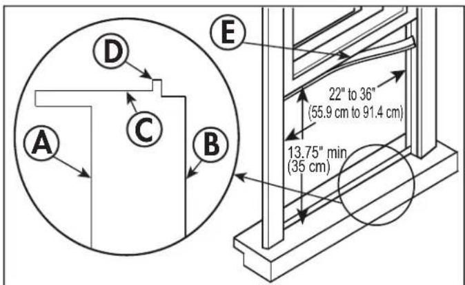
This air conditioner is designed to fit inside a standard double-hung window width opening widths of 22 - 36" (55.9 - 91.4 cm).
The lower sash must open sufficiently to allow a clear vertical opening of 35 cm (13.75").
This air conditioner is not designed for vertical, slider type windows or "through the wall" installation.
Ensure that the window and frame are structurally sound and free from dry or rotted wood.
Install the air conditioner on a side of the building which favors more shade than sunlight. If the appliance must be in direct sunlight, it is advisable to provide a shade awning to ensure efficient functioning.
Do not install the appliance where leakage of combustible gas is suspected.
This air conditioner is designed to evaporate condensation under normal conditions. Under extremely hot or humid conditions, excess condensation may overflow to the outside. The air conditioner should be installed where condensation cannot drip on pedestrians or neighboring properties.
Provide sufficient clearance around the appliance to allow ample air circulation. The rear of the appliance should be outdoors, it should not be in a garage or another room. Keep the appliance away from obstacles and at least 30" above the ground. Ensure that curtains and other obstructions do not block air flow.
A. Interior wall
B. Exterior wall
C. Inner window sill
D. Offset
E. Seal foam
Wooden Windows
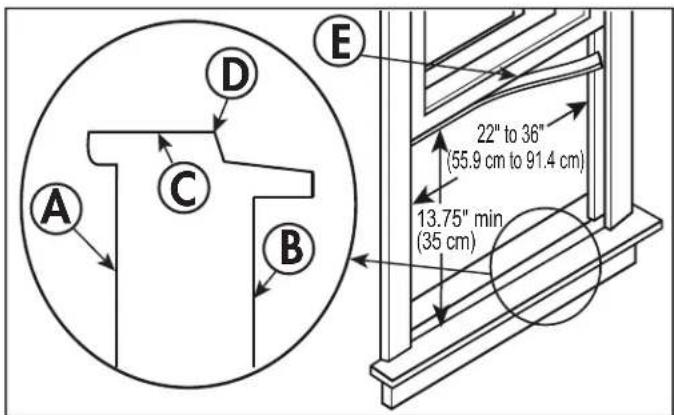
Vinyl-Clad Windows
INSTALLATION INSTRUCTIONS
REQUIRED TOOLS
• Phillips screwdriver
- Flat head screwdriver
- Pencil
• Measuring Tape
• Carpenter's Level
- Drill and 1/8" drill bit
Note: Save the shipping carton and packing materials for future storage or transportation. Please check the contents of the accessory bags against the below check list prior to installation.
INCLUDED ACCESSORIES
| 1/2" type B screw (x2) * | 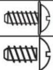 | |
| 1/4" type B screw (x2) * | ||
| 1" type A screw (x2) * | 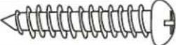 | |
| 1/2" type A screw (x3) * | 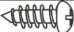 | |
| Support bracket | 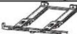 | |
| Right extension arm | 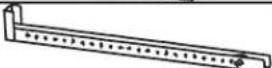 | |
| Right extension arm (short) | 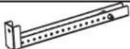 | |
| Main support pin (x2) * | 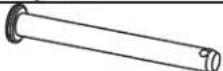 | |
| Cotter pin (x2) * | 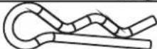 | |
| Right open window bracket | 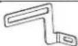 | |
| Left open window bracket | 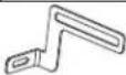 | |
| Side arm foam (x2) |  | |
| Window sash lock | 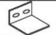 | |
| Window sash foam |  | |
| Window sealing foam | 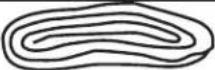 | |
| Bracket sealing foam | 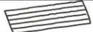 | |
| Additional side arm foam | 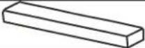 | |
* Denotes extra hardware provided in separate bag.
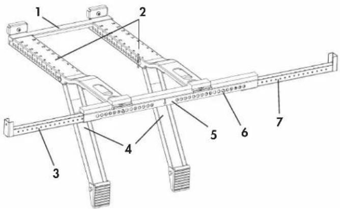
SUPPORT BRACKET DETAILS
- Rear cross brace
- Main support
- Left extension arm
- Angled support arms
- Horizontal bracket
- Spring push pin
- Right extension arm
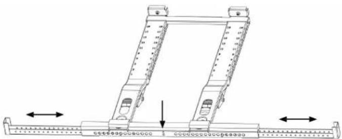
PREPARE THE SUPPORT BRACKET
- Find the center of the window sill and lightly mark it with a pencil.
- Measure the width of the window.
- Adjust the left extension arm, then install and adjust the right extension arm to the correct width by pressing the spring push pins. Note that the bracket may be slightly offset to the left of center when placed in the window.
- Apply the bracket sealing foam to the bottom of the left and right extension arms.
Important:
- Windows with widths between 26 - 36" should use the right extension arm.
- Windows with widths between 26 - 26" should used the short right extension arm
natural_image
Technical line drawing of a mechanical assembly with two vertical supports and directional arrows indicating movement (no text or symbols)INSTALLATION INSTRUCTIONS
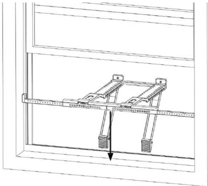
INSTALL THE SUPPORT BRACKET
Install the support bracket into the window opening. Ensure that the horizontal bracket and extension arms are located on the indoor side of the window.
natural_image
Technical line drawing of a mechanical lifting device mounted on a frame, showing structural components and a downward arrow (no text or symbols)Wooden Window Sill Vinyl-Clad Window Sill
natural_image
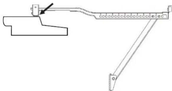
Technical line drawing of a mechanical lever system with pivot and pivot points (no text or symbols)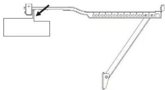
natural_image
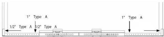
Mechanical linkage diagram showing a lever system with pivot point and guide rail (no text or labels)For wooden window sills or fl at window sills, secure the bracket to the window sill by drilling 1/8" pilot holes and installing the 1/2" and 1" type A screws as shown.
For vinyl-clad window sills, secure the bracket to the window sill by drilling 1/8" pilot holes and installing the 1/2" type A screws as shown.

INSTALLATION INSTRUCTIONS
Angled Support Arms
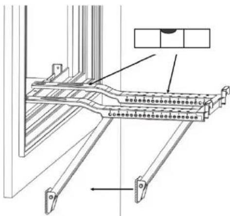
Move the angled support arms toward the exterior wall until the feet touch the wall.
Place the level on the support bracket and adjust the support arms so that it is tilted 1/4 bubble downward toward the outside. The level bubble should appear as shown.
natural_image
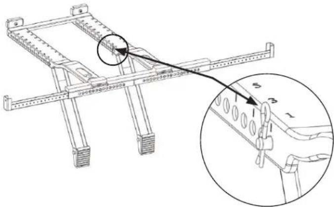
Technical line drawing of a structural frame assembly with mounting brackets and a component detail (no text or symbols)Insert the main support pin through the holes in the support bracket and angled support arms. Ensure that the pins on both sides are in the same numbered hole.
If further adjustment is needed, use alternate holes where the main supports attach to the horizontal bracket.
Check the level again and ensure the bracket feels secure. After making any necessary adjustments, insert the cotter pins into the main support pins.
If necessary, cover the holes in the front of the bracket with the bracket sealing foam.
natural_image
Technical line drawing of a mechanical assembly with mounting brackets and structural supports (no text or symbols)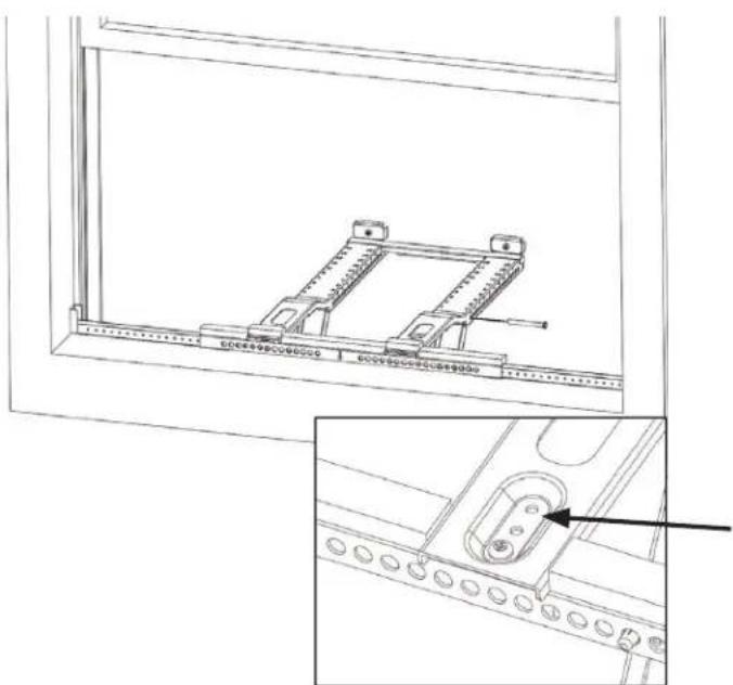
natural_image
Technical line drawing of a mechanical assembly with mounting holes and a bracket, shown from an exploded view (no text or symbols)INSTALLATION INSTRUCTIONS
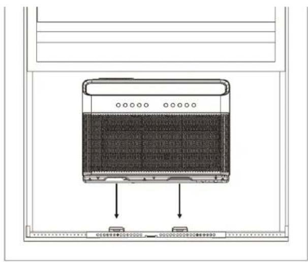
INSTALL THE AIR CONDITIONER
Set the air conditioner on top of the support bracket. Ensure the grooves on the bottom of the air conditioner align with the support bracket. Using a level, check for the proper tilt toward the outside.
natural_image
Diagram of a server rack with two labeled ports and a central display panel (no text or symbols)Pull the window down into the slot in the air conditioner to hold it steady but do not close it all the way yet.

natural_image
Line drawing of a front-mounted air conditioner unit with ventilation slots and a rack-mounted unit (no text or symbols visible)Fold down both side arm hinges.
natural_image
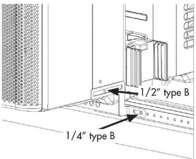
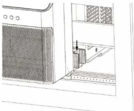
Line drawing of a microwave oven mounted on a rack, showing ventilation slots and a close-up of the lid (no text or symbols)Install the open window brackets using the provided screws as shown.
Warning: Failing to install the open window brackets could cause injury or property damage.
INSTALLATION INSTRUCTIONS
FOAM INSTALLATION
Measure the distance between the side arm hinge and the closest part of the window frame in side with the side arm. Add 1/4" to this distance and cut the side arm foam to the correct length.
natural_image
Technical line drawing of a refrigerated appliance with internal components and a close-up view of the interior (no text or symbols)Apply the window sealing foam to the side arm foam as shown. Note that the window sealing foam attaches to the side next to the air conditioner.
Wooden Window Sill Vinyl-Clad Window Sill
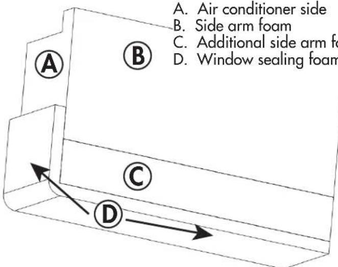
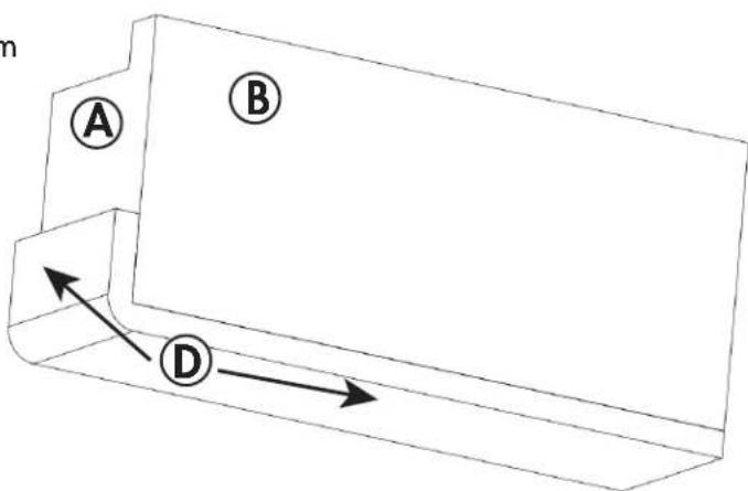
Insert side arm foam into the side arm hinge until the top front of the side arm is flush with the top of the hinge. Complete the side foam installation on both sides of the unit.
natural_image
Technical line drawing of a cabinet or rack with ventilation grilles and a door, showing no text or symbols.INSTALLATION INSTRUCTIONS
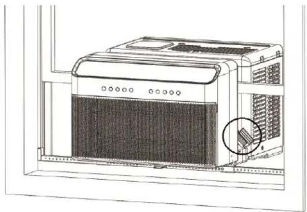
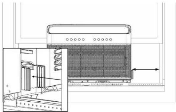
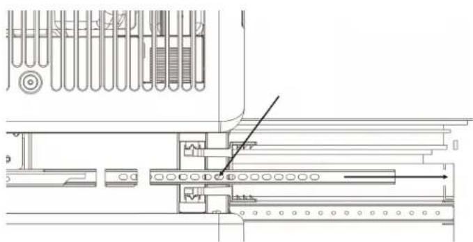
ANTI TIP BRACKET
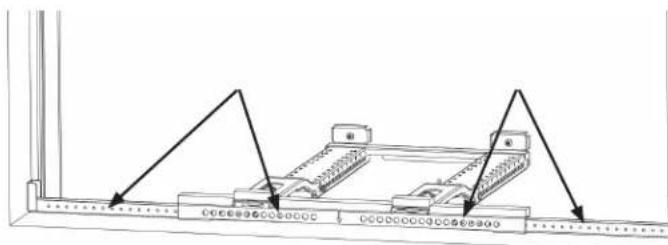
The anti tip brackets must be extended into the window track opening until. Remove the screw from the anti tip bracket, extend it as far as it will go to the side of the window and then secure it with the same screw.
Warning: The anti tip brackets must be extended into the window track opening. Failure to use the anti tip brackets can cause serious injury or damage.
natural_image
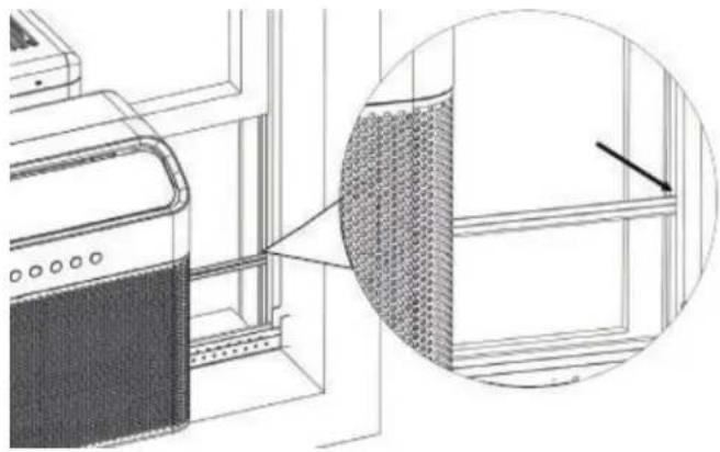
Technical line drawing of a mechanical assembly with no visible text or symbolsSee below for an example of what the anti tip bracket should look like when properly installed. Note that the side arm foam has been removed from this images for illustration purposes.
natural_image
Technical line drawing of a wall-mounted air conditioner unit with a magnified inset showing internal mesh structure (no text or symbols)WINDOW SEALING FOAM
Install a strip of window sealing foam to the bottom of the lower sash to seal any small gaps between the window and the air conditioner. Make sure the window is completely closed and then check for gaps. Fill any gaps with the remaining foam as needed.
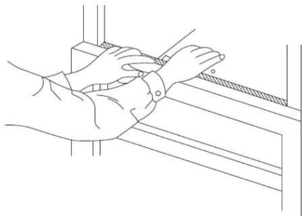
Extend the integrated window locks, located in the U-channel, until they contact the window.
Cut the window sash foam and insert it into the space between the upper and lower sashes.
natural_image
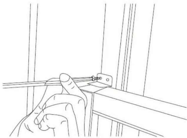
Line drawing of hands adjusting a metal bracket with a hatched pattern (no text or symbols)SASH LOCK
For added security, install the optional sash lock. Secure the sash lock in place using 1/2" type A screws as shown.
natural_image
Line drawing of a hand holding a metal bracket with a clip, no text or symbols presentOPERATING INSTRUCTIONS
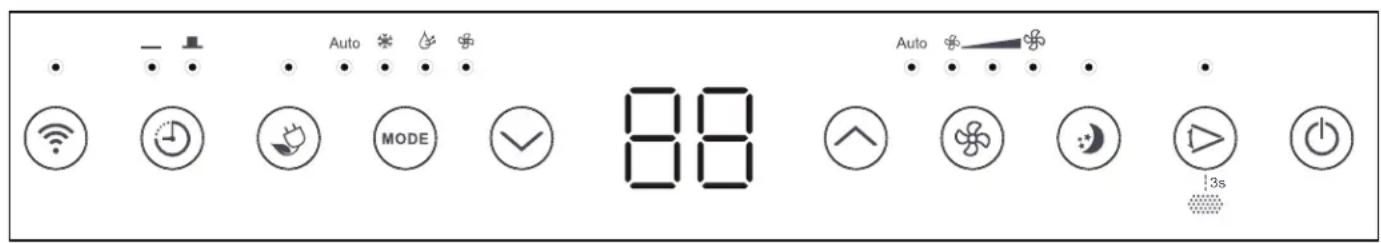
CONTROL PANEL
- WIRELESS CONNECT: Press to activate the wireless connection feature.
- TIMER: Press to activate the timer feature.
- ECO: Press to activate the ECO feature.
- MODE: Press to set the desired mode.
- TEMPERATURE CONTROL BUTTONS: Press to change the temperature setting. Press and hold the temperature control buttons at the same time for 3 seconds to change the temperature scale being displayed. The temperature can be set between 16 - 30°C (60 - 86°F).
- FAN: Press to set the desired fan speed.
- SLEEP: Press to activate the sleep feature.
- SWING: Press to initiate the auto swing feature. Press again when the louver reaches the desired angle. Press and hold the swing button for 3 seconds to reset the filter after cleaning.
- ON/OFF: Press to turn the appliance on or off.
MODE
Press the mode button to choose the desired mode.
Auto
Auto mode will automatically set cooling or fan only operation based on the current temperature in the room. Fan speed cannot be adjusted in this mode.
Cool
Choose cool mode to set the cooling function. Use the temperature control buttons to choose the desired temperature. The fan speed can be adjusted by pressing the fan button.
Dry
Choose dry mode to set the dehumidifying function. Condensed water will drain out the back of the unit. Fan speed cannot be adjusted in this mode.
Fan
Fan mode will run the internal fan without engaging the cooling function. The fan speed can be adjusted by pressing the fan button.
OPERATING INSTRUCTIONS
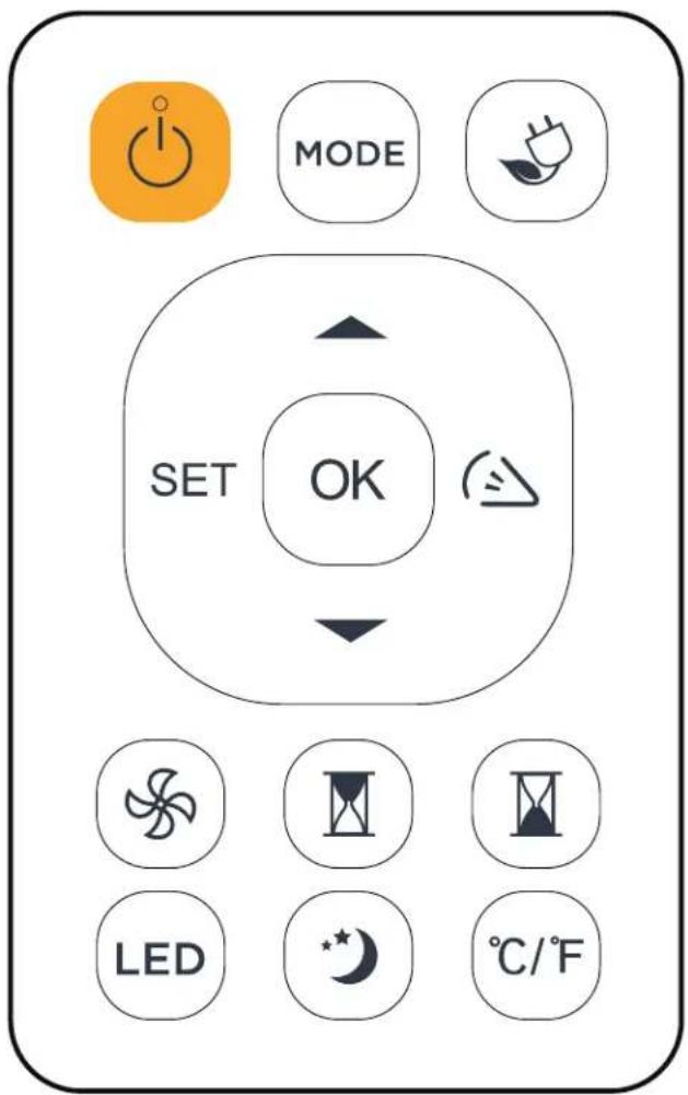
REMOTE CONTROL
- ON/OFF: Press to turn the appliance on or off.
- MODE: Press to set the desired mode.
- ECO: Press to activate the ECO feature.
- WIRELESS CONNECT: Press to activate the wireless connection feature.
- TEMPERATURE CONTROL BUTTONS: Press to change the temperature setting.
- SWING: Press to initiate the auto swing feature. Press again when the louver reaches the desired angle.
- FAN: Press to set the desired fan speed.
- TIMER ON: Press to activate the automatic on timer.
- TIMER OFF: Press to activate the automatic off timer.
- LED: Press to turn off the display on the appliance.
11.SLEEP: Press to activate the sleep feature. - C^/F^ : Press to change the temperature scale being displayed.
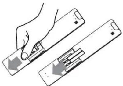
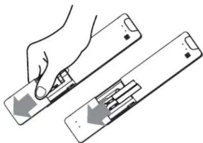
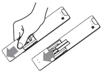
REPLACING REMOTE BATTERIES
- Slide the back cover from the remote control downward to expose the battery compartment.
- Insert new batteries. Match the (+) and (-) on the batteries to the markings on the compartment.
- Slide the battery cover back into place.
natural_image
Illustration of a hand holding a device with an arrow indicating left motion (no text or symbols present)Important Notes
- The remote control must be used within 8 meters of the appliance.
- The appliance will beep when a signal is received from the remote.
- Curtains and direct sunlight can interfere with the remote signal.
- Remove the batteries if the remote will not be used for more than 2 months.
- Do not mix old and new batteries or batteries of different types.
- Do not dispose of batteries as unsorted municipal waste. Refer to local laws for proper disposal of batteries.
OPERATING INSTRUCTIONS
REMOTE CONTROL REGULATIONS
This equipment has been tested and found to comply with the limits for a Class B digital device, pursuant to Part 15 of the FCC Rules. These limits are designed to provide reasonable protection against harmful interference in a residential installation. This equipment generates, uses and can radiate radio frequency energy and, if not installed and used in accordance with the instructions, may cause harmful interference to radio communications. However, there is no guarantee that interference will not occur in a particular installation.
If this equipment does cause harmful interference to radio or television reception, which can be determined by turning the equipment off and on, the user is encouraged to try to correct the interference by one or more of the following measures:
- Reorient or relocate the receiving antenna
- Increase the separation between the equipment and receiver
- Connect the equipment into an outlet on a circuit different from that to which the receiver is connected
- Consult the dealer or an experienced radio/TV technician for help
Changes or modifications not approved by the party responsible for FCC and Industry Canada compliance could void the user's authority to operate the equipment. This appliance complies with Part 15 of the FCC Rules and license-exempt RSS standards.
Operation is subject to the following conditions:
- This device may not cause interference.
- This device must accept any interference received, including interference that may cause undesired operation.
This equipment complies with FCC RF and IC RSS-102 radiation exposure limits set forth for an uncontrolled environment. This equipment should be installed and operated with minimum distance 20cm(8 inches) between the radiator and your body.
This device complies with RSS-247 of Industry Canada. Operation is subject to the condition that this device does not cause harmful interference.
This device complies with Canadian CAN ICES-3 (B) / NMB-3 (B)
This device contains:
FCC ID: 24951-MZNA19
IC: 12575A-MDNA19
OPERATING INSTRUCTIONS
WIRELESS CONNECTION
This appliance can be controlled with a wireless application on your wireless device.
Visit https://www.danby.com/support/#apps to download the application and learn about its operation.
TIMER
Press the timer button and either the timer on or timer off indicator will illuminate to indicate that either the auto start or auto stop cycle is being set. For some units continuing to press the timer button will cancel the timer settings.
Press the temperature control buttons to change the set time by 0.5 hour increments up to 10 hours and then at 1 hour increments up to 24 hours. The display will count down the time remaining.
The selected time will register in 5 seconds and the system will automatically revert back to display the previous temperature setting or room temperature.
Turning the appliance on or off at any time or adjusting the timer setting to 0 will cancel the timer settings.
SLEEP
Press the sleep button to initiate the sleep feature which will conserve energy during sleeping hours. This feature is available in cool mode.
When selected, the set temperature will increase by 2^ 30 minutes after sleep mode is initiated. 30 minutes later, the temperature will increase by another 2^ . The new temperature will be maintained for 7 hours before the appliance returns to normal operation.
The sleep feature can be canceled at any time by pressing the sleep button.
ECO
The ECO feature is available in cool, dry and auto modes. The fan will continue to run for 3 minutes after the compressor shuts off. The fan then cycles on for 2 minutes in 10 minute intervals until the room temperature is above the set temperature and the compressor turns back on. This will minimize how often the compressor turns on.
LOCK
On the remote control, press and hold the LED and the C°/F° buttons at the same time for 5 seconds to activate the control panel lock. Buttons on the control panel and the remote control cannot be pressed when the control panel lock is active.
Press and hold the LED and C°/F° buttons at the same time for 5 seconds to deactivate the control panel lock.
CARE & MAINTENANCE
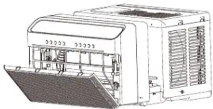
AIR FILTER
The air fi liter should be cleaned at least once a month. The air fi liter may require more frequent cleaning if there is signifi cant dander or fur in the air.
- Push the vent handle to the vent closed position. Open the front panel.
- Hold the filter in the center and pull it up and out.
- Use a vacuum cleaner with a soft brush attachment to remove any large debris or dust build up from the air filter.
- Wash the filter in lukewarm, soapy water, below 40^ C ( 104^ F), or use a neutral cleaning agent.
- Rinse the filter with clean water and dry thoroughly before reinstalling in the appliance.
Note: Do not operate the appliance without the air fi lter installed.
natural_image
Technical line drawing of a mechanical device with internal components and mounting base (no text or symbols)SOUNDS
All of the following sounds may be produced during normal operation:
Pinging or swishing
- Droplets of water hitting the condenser may cause pinging or swishing noises
Gurgle or hiss
- Refrigerant passing through the evaporator can sometimes sound like gurgling or hissing
High pitched chatter
- High efficiency compressors may produce a high pitched chatter during the cooling cycle
Rushing air
- The fan will produce the sound of rushing air from the front of the air conditioner
"Da-da" sound when unit is turned on
- This sound is produced by the compressor starting
CLEANING
To avoid possible electric shock, ensure that the appliance is unplugged before performing any cleaning or maintenance.
The outside of the appliance can be wiped clean with a soft cloth or with a lukewarm, damp cloth if necessary.
Do not use gasoline, benzene, thinner or any other chemicals to clean this appliance as these substances can cause damage to the fi nish and deformation of plastic parts.
Never pour water directly onto the appliance as this will cause deterioration of electrical components and wiring insulation.
END OF SEASON CARE
Before removing the appliance from service for the year, operate the appliance on high fan mode for half a day to ensure the inside of the appliance is dry. This will help avoid the growth of mold or mildew inside the appliance. Ensure the filter is clean and dry. Store the appliance covered in a dry location.
Note: When installing or removing the appliance from the window, ensure that caution is taken to prevent it from falling backward. It is recommended that installation or removal is completed with assistance to prevent injury to persons or damage to property or the appliance.
DISPOSAL
Check for local regulatory compliance regarding approved and safe disposal of this appliance.
FREQUENTLY ASKED QUESTIONS
Can I leave my AC in place through the winter?
This is not recommended. Please bring your AC unit indoors during the winter months.
What are the standard wattage and amps used?
Information pertaining to watts and amps can be found on the rating plate located on the side of the unit.
Can I use an extension cord?
No, an extension cord may not be used.
Why do I hear water in the unit?
Water is collected during the air conditioning process. This water will drain out of the unit and onto the ground and is why the unit should be installed on a slight downward tilt.
How much does it cost to run the unit?
Please refer to the energy guide.
Odors
Odour is caused by the formation of mold or mildew on internal surfaces. This can happen when there is poor air circulation, a dirty filter or the air conditioner was not used for a period of time.
- Ensure the filter is clean.
- Run the unit on fan mode to remove any internal moisture.
- Ensure that back of the unit is installed downward slope so the water can drain outside.
If the odour continues, we suggest using an algaecide tablet. Unplug the unit, then place half the tablet through each side of the unit, through the slots on the side (usually on the portion outside of the window). Please do not place the tablet through the front grill.
TROUBLESHOOTING
Appliance will not operate
- Plug is not fully inserted into the wall outlet
- Blown fuse or circuit breaker
Insuffi cient cooling
- Air filter is dirty
- Blocked air flow
- Appliance size is too small for application
Noise
• Normal sounds are listed in the operating instructions
- Vibration or rattling can be produced by inadequate support in window installation, refer to installation instructions to ensure unit is properly installed
Water dripping inside
- Appliance is not properly angled to allow water to drain to the outside
Water dripping outside
- On very hot or humid days dripping water from the back of the appliance is normal
Frost build up
- When outdoor temperatures are below 18.3°C (65°F) frost may form when the appliance is in cooling mode
- Switch the appliance to fan only mode until the frost melts
Air conditioner starts and stops frequently
• Air filter is dirty causing insufficient air flow
- Outside temperature is excessively hot, set the fan speed higher to bring air through the cooling coils more rapidly
LIMITED "IN HOME" WARRANTY
This quality product is warranted to be free from manufacturer's defects in material and workmanship, provided that the unit is used under the normal operating conditions intended by the manufacturer.
This warranty is available only to the person to whom the unit was originally sold by Danby Products Limited (Canada) or Danby Products Inc. (U.S.A.) (hereafter "Danby") or by an authorized distributor of Danby, and is non-transferable.
TERMS OF WARRANTY
Plastic parts are warranted for thirty (30) days from the date of purchase, with no extensions provided.
First 24 months During the first twenty four (24) months, any functional parts of this product found to be defective, will be repaired or replaced, at warrantor's option, at no charge to the original purchaser.
To obtain service Contact the dealer where the unit was purchased, or contact the nearest authorized Danby service depot, where service must be performed by a qualified service technician. If service is performed on the unit by anyone other than an authorized service depot, all obligations of Danby under this warranty shall be void.
Boundaries of in-home service Danby reserves the right to limit the boundaries of "In Home Service" to the proximity of an authorized service depot. Any appliance requiring service outside the limited boundaries of "In Home Service", will be the consumer's responsibility to transport at their own expense to the original point of purchase or a service depot for repair. If the appliance is installed in a location that is 100 kilometers (62 miles) or more from the nearest service center, it must be delivered to the nearest authorized Danby Service Depot by the purchaser.
Transportation charges to and from the service location are not protected by this warranty and are the responsibility of the purchaser.
Nothing within this warranty shall imply that Danby will be responsible or liable for any spoilage or damage to food or other contents of this appliance, whether due to any defect of the appliance, or its use, whether proper or improper.
EXCLUSIONS
Save as herein provided, by Danby, there are no other warranties, conditions, representations or guarantees, express or implied, made or intended by Danby or its authorized distributors and all other warranties, conditions, representations or guarantees, including any warranties, conditions, representations or guarantees under any Sale of Goods Act or like legislation or statute is hereby expressly excluded. Save as herein provided, Danby shall not be responsible for any damages to persons or property, including the unit itself, howsoever caused or any consequential damages arising from the malfunction of the unit and by the purchase of the unit, the purchaser does hereby agree to indemnify and hold harmless Danby from any claim for damages to persons or property caused by the unit.
GENERAL PROVISIONS
No warranty or insurance herein contained or set out shall apply when damage or repair is caused by any of the following:
1) Power failure.
2) Damage in transit or when moving the appliance.
3) Improper power supply such as low voltage, defective house wiring or inadequate fuses.
4) Accident, alteration, abuse or misuse of the appliance such as inadequate air circulation in the room or abnormal operating conditions (i.e. extremely high or low room temperature).
5) Use for commercial or industrial purposes (i.e. If the appliance is not installed in a domestic residence).
6) Fire, water damage, theft, war, riot, hostility, acts of God such as hurricanes, floods etc.
7) Service calls resulting in customer education.
8) Improper Installation (i.e. Building-in of a free standing appliance or using an appliance outdoors that is not approved for outdoor application, including but not limited to: garages, patios, porches or anywhere that is not properly insulated or climate controlled).
Proof of purchase date will be required for warranty claims; retain bills of sale. In the event that warranty service is required, present the proof of purchase to our authorized service depot.
Warranty Service
In Home
Danby Products Limited
PO Box 1778, Guelph, Ontario, Canada N1H 6Z9
Telephone: |519| 837-0920 FAX: |519| 837-0449
1-800-263-2629
04/17
Danby Products Inc
PO Box 669, Findlay, Ohio, U.S.A. 45840
Telephone: (419) 425-8627 FAX: (419) 425-8629
ATTENTION: RISQUE D'INCENDIE
INSTRUCTIONS D'INSTALLATION
OUTILS REQUIS
PRÉPARER LE SUPPORT
natural_image
Technical line drawing of a mechanical assembly with two vertical supports and directional arrows indicating movement (no text or symbols)INSTRUCTIONS D'UTILISATION
INSTALLER LE SUPPORT
natural_image
Technical line drawing of a mechanical lifting device inside a window frame (no text or symbols)natural_image
Technical line drawing of a mechanical linkage or lever system (no text or symbols)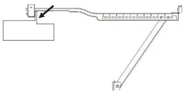
natural_image
Pure mechanical linkage diagram without any text, numbers, or symbols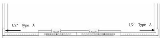
INSTRUCTIONS D'INSTALLATION
Bras de support inclinés
natural_image
Technical line drawing of a structural frame assembly with mounting brackets and a component detail (no text or symbols)natural_image
Technical line drawing of a mechanical assembly with mounting brackets and structural supports (no text or symbols)
natural_image
Technical line drawing of a mechanical assembly with mounting holes and a bracket, shown from an inset view (no text or symbols)INSTRUCTIONS D'UTILISATION
INSTALLER LE CLIMATISEUR
natural_image
Technical diagram of a device with internal components and mounting base (no text or symbols)natural_image
Line drawing of a front-mounted air conditioner unit with control panel and ventilation slots (no text or symbols)natural_image
Line drawing of a microwave oven with a close-up inset showing the lid and base panel (no text or symbols)natural_image
Technical line drawing of a refrigerated industrial machine with internal components and mounting base (no text or symbols)natural_image
Line drawing of a cabinet interior with ventilation grilles and shelf, no text or symbols presentINSTRUCTIONS D'UTILISATION
SUPPORT ANTI-BASCULE
natural_image
Technical line drawing of a mechanical assembly with no visible text or symbolsnatural_image
Technical line drawing of a window frame with a magnified inset showing mesh structure (no text or symbols)MOUSSE D'ÉTANCHÉITÉ DE FENÊTRE
natural_image
Line drawing of hands adjusting a metal bracket with a diagonal tab (no text or symbols)SERRURE DE FENÊTRE
natural_image
Line drawing of a hand holding a metal bracket with a clip, no text or symbols presentINSTRUCTIONS D'UTILISATION
PANNEAU DE CONTRÔLE
MODE
natural_image
Illustration of a hand holding a device with arrows indicating movement or process (no text or symbols present)INSTRUCTIONS D'UTILISATION
RÈGLEMENTS DE LA TÉLÉCOMMANDE
natural_image
Technical line drawing of a multi-chamber electric heater unit with cooling fins and internal components (no text or symbols)DES SONS
Danby Products Limited
PO Box 1778, Guelph, Ontario, Canada N1H 6Z9
PREPARA EL SOPORTE
natural_image
Technical line drawing of a mechanical assembly with directional arrows indicating movement (no text or symbols)natural_image
Technical line drawing of a mechanical lifting device mounted on a frame, showing structural components and a downward arrow (no text or symbols)natural_image
Technical line drawing of a mechanical linkage or support structure (no text or symbols)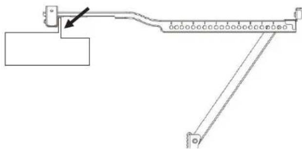
natural_image
Technical line drawing of a mechanical linkage system with no visible text or symbolsnatural_image
Technical line drawing of a mechanical assembly with mounting brackets and structural elements (no text or symbols)natural_image
Technical line drawing of a mechanical assembly with mounting brackets and structural supports (no text or symbols)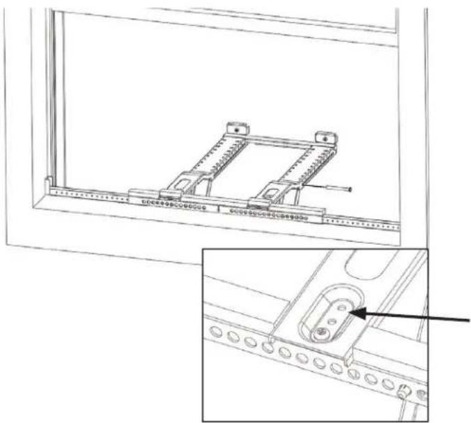
natural_image
Technical line drawing of a mechanical assembly with mounting brackets and a close-up inset showing a component detail (no text or symbols)natural_image
Line drawing of a front-mounted air conditioner unit with ventilation grilles and control panel (no text or symbols)natural_image
Line drawing of a microwave oven mounted on a rack, showing front panel and side panel (no text or symbols)natural_image
Technical line drawing of a mechanical device with internal components and directional arrows (no text or symbols)natural_image
Line drawing of a kitchen appliance with a mesh fan and shelf, showing no text or symbolsnatural_image
Technical line drawing of a mechanical assembly with no visible text or symbolsnatural_image
Technical line drawing of a window with a mesh pattern and an inset showing a magnified detail (no text or symbols)ESPUMA DE SELLADO DE VENTANAS
natural_image
Line drawing of hands adjusting a metal bracket with a diagonal tab (no text or symbols)MARCO DE BLOQUEO
natural_image
Line drawing of a hand holding a metal bracket with a small inset detail (no text or symbols)MODO
natural_image
Illustration of a hand holding a remote control panel with arrows indicating left and right movement (no text or symbols)natural_image
Technical line drawing of a mechanical device with cooling fins and internal components (no text or symbols)SONIDOS
Danby Products Limited
PO Box 1778, Guelph, Ontario, Canada N1H 6Z9
Telephone: [519] 837-0920 FAX: [519] 837-0449
1-800-263-2629
04/17
Danby Products Inc.
PO Box 669, Findlay, Ohio, U.S.A. 45840
Telephone: (419) 425-8627 FAX: (419) 425-8629
Danby Products Limited, Guelph, ON, Canada N1H 6Z9 Danby Products Inc., Findlay, Ohio, USA 45840