
RXPW4N - Smart Home DIMPLEX - Free user manual and instructions
Find the device manual for free RXPW4N DIMPLEX in PDF.
User questions about RXPW4N DIMPLEX
0 question about this device. Answer the ones you know or ask your own.
Ask a new question about this device
Download the instructions for your Smart Home in PDF format for free! Find your manual RXPW4N - DIMPLEX and take your electronic device back in hand. On this page are published all the documents necessary for the use of your device. RXPW4N by DIMPLEX.
USER MANUAL RXPW4N DIMPLEX
Device complying with the requirements of directives 2004/108/CE(ElectroMagnetic Compatibility) and 2006/95/CE (low voltage safety)
Because of changes in standards and equipment, the characteristics given in the text and the illustrations of this document are not binding unless confirmed by our services.
Programmateur Fil Pilote 4 zones 4 Zone Pilot Wire Programmer
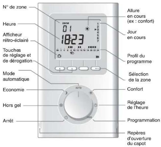
Description
Sommaire
INSTALLATION
Presentation 5
Emplacement. 7
Fixation 8
Raccordement 9
Mise en service 11
Vérification des raccordements fil pilote 12
UTILISATION
-zone FP 1 = borne 3
-zone FP 2 = borne 4
-zone FP 3 = borne 5
zone FP 4 = borne 6
Checking the pilot wire connections 34
USE
Time Setting 35
Programming 36
Automatic Mode 39
Absence mode 40
Manual mode 41
Continuous mode 42
Shutdown mode 42
Return to the initial settings 43
Mains failure 44
Characteristics 43
Warning
- Carefully read these instructions prior to installation.
The unit must be installed in compliance with currently applicable standards. - Always switch off the mains before installing or servicing the unit.
- Do not attempt to repair the unit yourself; after-sales service is available.
- Check that the fastenings are suited to the surface that the unit will be attached to (sheet of plaster, brick, etc.).
- The diagrams provided are simplified for greater clarity. The protective units and other accessories required by the standards are not illustrated. Standard UTE NF C15-100 and good practice must be adhered to. Connected or nearby equipment must not generate excessive interference (directive 2004/108/CE).
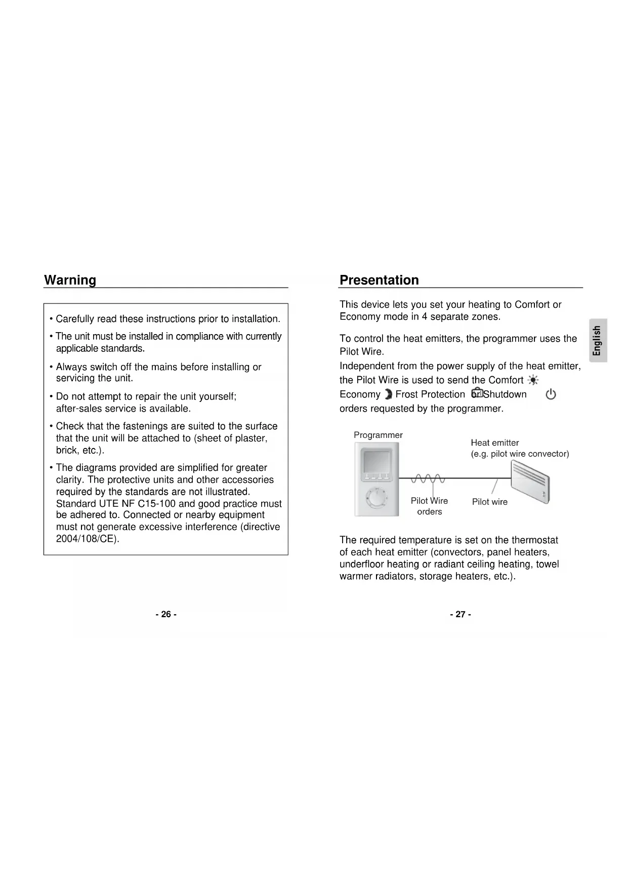
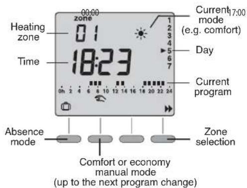
Presentation
This device lets you set your heating to Comfort or Economy mode in 4 separate zones.
To control the heat emitters, the programmer uses the Pilot Wire.
Independent from the power supply of the heat emitter, the Pilot Wire is used to send the Comfort
Economy Frost Protection Shutdown orders requested by the programmer.
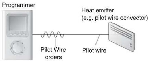
The required temperature is set on the thermostat of each heat emitter (convectors, panel heaters, underfloor heating or radiant ceiling heating, towel warmer radiators, storage heaters, etc.).
IMPORTANT: The heat emitter must be in automatic mode (PROG, AUTO, etc. depending on model) to receive orders from the programmer.
| Pilot Wire order (mode) | Setting on the heat emitter | Room temperature |
| Comfort | Comfort setting (thermostat knob) example: 19°C | 19°C |
| Economy | Economy setting (thermostat knob) example: 16°C or Comfort -X°C (depending on heat emitter model) | 16°C |
| Absence | Frost protection set to 7°C or 8°C (depending on model) | 7°C or 8°C |
| Shutdown | Heating shutdown | No heating |
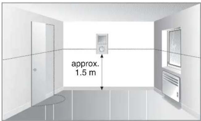
Location
It is advisable to install your device:
- where there is easy access, such as a corridor, living room or entrance hall
- close to a power supply and pilot wire entry point(s)
-on a wall at a height of approximately 1.5m
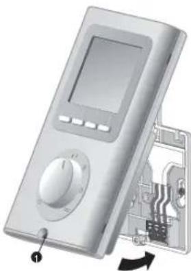
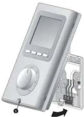
Mountings
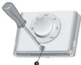
Switch off the mains power before handling the device.
- Lift off the cover by using a screwdriver.
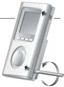
- Separate the programmer from its base by loosening the clamp screw (captive screw).
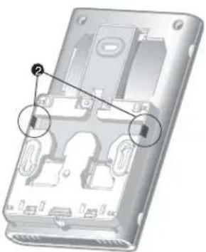
- Secure the base using three screws and pegs or fit onto a flush-mounted box (distance between centres 60~mm ).
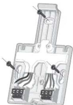
Note: The base must be secured using 3 screws.
Note: To protect the power supply to the programmer, you must use a 10 A circuit breaker at least (do not use a 2 A circuit breaker).
Connection
To connect the programmer, you will need:
- a 230V mains power supply (live and neutral)
- entry point(s) behind the unit for the pilot wire(s) controlling one or more convectors
- if you want to connect more than one pilot wire to the programmer, you must use a connecting strip (terminal block) so that the pilot wires are not all directly connected to the terminal
- circuit breakers (not supplied) fitted in the electrical switchboard
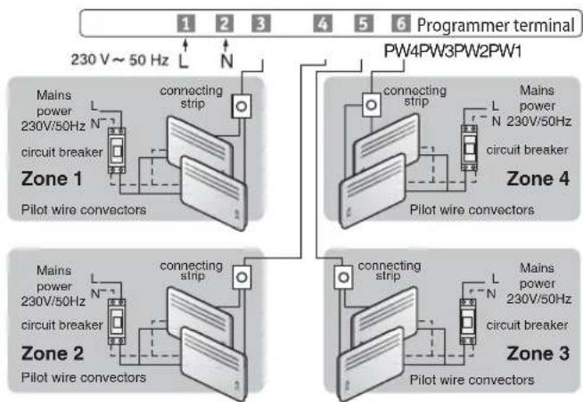
- Connect the two power leads to terminals 1 and 2
- Connect the control wires:
- PW 1 zone = terminal 3
- PW 2 zone = terminal 4
- PW 3 zone = terminal 5
- PW 4 zone = terminal 6
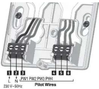
Partitions (2) that can be removed by pliers are provided for passing the connection wires if required.
- Fit the programmer onto the tab of the base and secure it with the clamp screw ①.
- Place the cover back on the programmer
The programmer is ready to be used.
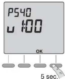
Starting up
Turn the knob to end press the right-hand button for 5 seconds until P540 is displayed (maintenance menu reserved for the installer).
Press OK.
The screen displays CF01.
CF01 - Select AUTO mode operation
Selection of 3 modes. Press ^+ to make your choice, OK to confirm it and exit the maintenance menu.

| CF01 Operating mode selection | Comfort / Economy (default) Mode |
| Comfort / Frost protection Mode | |
| Comfort / Shutdown Mode |
Checking the pilot wire connections
When the unit is first switched on, place all the installation's convectors on Comfort (with the set-point on its maximum setting).
If the display remains "normal", this means that no problem has been detected.
If the programmer detects a problem, it displays:
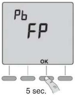
Check the connection of the pilot wires to the heat emitters and find a solution to any problems.
When the check has been carried out, test the pilot wire again by pressing OK for 5 seconds (time for the test: approx. 1 minute 30 sec.).
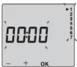
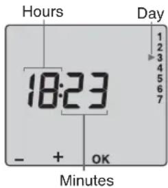
Time setting
Turn the knob to 品
The days flash.
Press + or - to make your choice, OK to confirm it and go to the next setting.
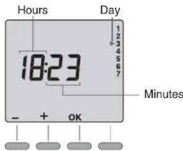
Repeat the operations to set the hours and minutes.
Turn the knob to exit the setting mode.
Programming
When starting up, the "Comfort mode from 6am to 11pm" program is applied to all the days of the week and all the zones.
Turn the knob to PROG to change the programming. The 1st time slot of zone 1 flashes.
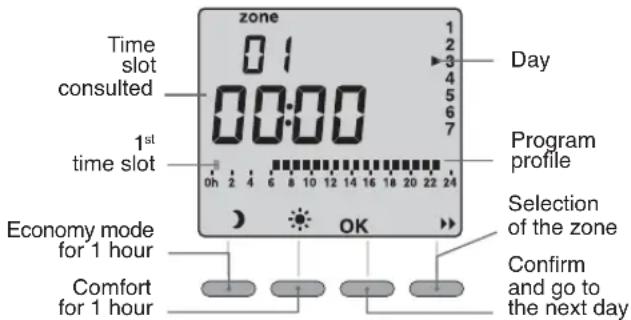
1. Select the zone to program
Press the button.
2. Create your program
Programming starts on day 1 at midnight. Press buttons or set your different Comfort or Economy periods (depending on the settings made at the CF01 menu).
3. Confirm the program
Press the OK button to confirm and continue on to the next day to program it separately. Turn the knob to exit the programming mode.
OR
4. Confirm and copy the program
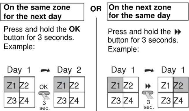
Press the OK button to confirm.
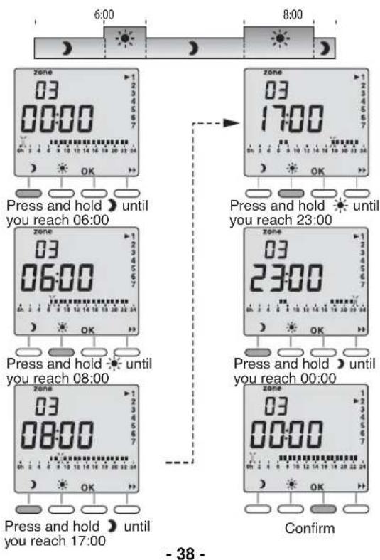
Example: Comfort from 6:00 to 8:00
and from 17:00 to 23:00 in zone 3
Press the button to change the zone
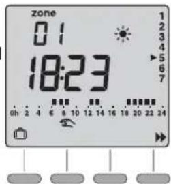
Automatic mode
Turn the knob to AUTO.
00:00
The device follows the program.
Press the button to select the zone to consult.
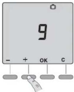
Absence mode
This mode is used to set all the heating zones to Frost protection mode for an adjustable period of 1 to 365 days.
From the automatic mode (AUTO), press the button.
The number of days flash on and off.
Press + or - to set the number of days.
Example:
leaving on 10 January, returning on 19 January, indicate 9 days. Automatic operation will restart on 19 January at 00.00h
Press OK to confirm.
To cancel the absence mode (e.g. when returning early), press the C button or turn the knob.
Manual mode
This mode is used to go from Comfort to Economy mode (depending on the setting in menu CF01) or conversely until the next program change for the zone.
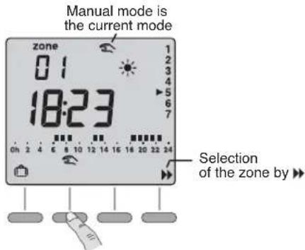
Press the button to select the zone and press the button.
Example:
when in economy mode (depending on the setting in menu CF01), pressing the button allows you to go to comfort mode.
To cancel the manual mode, press the button again or turn the knob.
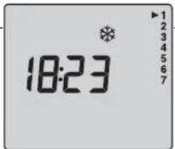
Continuous mode
To set the heating to Frost Protection mode for an indefinite duration.
Turn the knob to
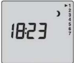
To set the heating to Economy mode for an indefinite duration.
Turn the knob to
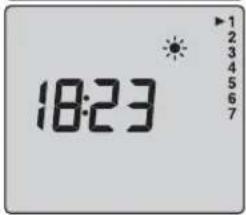
To set the heating to Comfort mode for an indefinite duration.
Turn the knob to
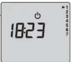
Shutdown mode
To shut down the heating (in summer, for example).
Turn the knob to
-42-
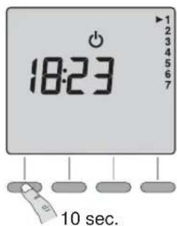
Return to the initial settings
You can carry out a general reset to return to the factory settings:
- Return to the default program.
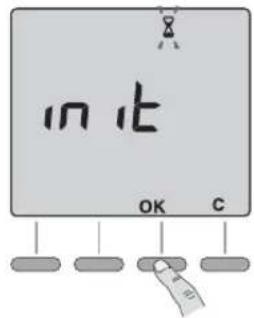
Turn the knob to then press the left-hand button for 5 seconds until init is displayed.
To cancel the reset, press C.
Press OK to confirm, an hourglass is displayed during the time needed for the reset operation (approx. 15 seconds).
Return to the shutdown mode display.
-43-
Mains failure
You must reset the time after a lengthy mains outage.
When the power is restored, the time and date will flash.
Reset the time.
Turn the knob to The days flash.
Press + or - to make your choice, OK to confirm it and go to the next setting.
Repeat the operations to set the hours and minutes.
Turn the knob to exit the setting mode.
Characteristics
- 230 V, 50 Hz power supply, +/- 10%
- Clock back-up in event of mains outage: 4 hours (by capacitor)
Permanent back-up of the programming
Power consumption: 2 VA
Class II insulation
- Dimensions
Without base: 134 × 80 × 25 ~mm
Protection index: IP 30
- Wall-mounted or on base
Install in an environment with normal pollution levels
Storage temperature: -10^ to +70^
- Operating temperature: 0^ to +40^
4 pilot wire outputs max. 40mA 230 V (GIFAM standard)
Max. cable length 50m
Note: All other settings are unchanged.