237 - Pump Liberty Pumps - Free user manual and instructions
Find the device manual for free 237 Liberty Pumps in PDF.
| Brand | Liberty Pumps |
| Model | 237 |
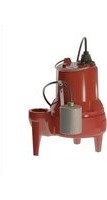
| Product Type | Submersible Dewatering Pump |
| Motor Power | 1/3 hp (approx. 0.25 kW) |
| Body Material | Polypropylene/Aluminum |
| Switch | Vertical Float Switch |
| Minimum Sump Diameter | 25 cm (10 in) |
| Minimum Sump Depth | 30.5 cm (12 in) above pump |
| Maximum Discharge Head | 6.4 m (21 ft) |
| Discharge Connection | 1½ in NPT threaded |
| Air Vent Hole | Integrated into volute housing |
| Thermal Protection | Yes (built into motor) |
| Power Cord Length | Approximately 3 m (standard model) |
| Rated Voltage | 115 V, 60 Hz (single phase) |
| Maximum Water Temperature | 60 °C (140 °F) |
| Approximate Weight | 6.5 kg |
| Warranty | 3-year limited |
| Certifications | Complies with electrical and plumbing codes |
| Maintenance | Sealed bearings, no lubrication needed; check float and inlet regularly |
| Applications | Sump pump, residential drainage |
Frequently Asked Questions - 237 Liberty Pumps
User questions about 237 Liberty Pumps
0 question about this device. Answer the ones you know or ask your own.
Ask a new question about this device
Download the instructions for your Pump in PDF format for free! Find your manual 237 - Liberty Pumps and take your electronic device back in hand. On this page are published all the documents necessary for the use of your device. 237 by Liberty Pumps.
USER MANUAL 237 Liberty Pumps
For Submersible Sump Pumps
*Do not throw away or lose this manual. Keep it with the installation and refer to it often.
Submersible Models 1/4 hp
240-Series...Cast Iron
240 Manual
241 Wide Angle Float
243 Wide-Angle Float w/Series Plug
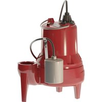
247 Vertical Float
Submersible Models 1/3 hp
230-Series...Poly/Aluminum
230 Manual
231 Wide Angle Float
233 Wide-Angle Float w/series plug
237 Vertical Float
Submersible Models 1/2 hp
450-Series...Poly/Aluminum
450 Manual
451 Wide Angle Float
453 Wide-Angle Float w/series plug
457 Vertical Float
IMPORTANT:
Prior to installation, record Model, Serial Number, and Code Number from pump nameplate for future reference.
MODEL ____
SERIAL
CODE ____
INSTALLATION
DATE ____
1. General Information – All Models
Before Installation, read the following instructions carefully. Each Liberty pump is individually factory tested to assure proper performance. By closely following these instructions, potential operating problems should be eliminated, providing years of trouble-free service.
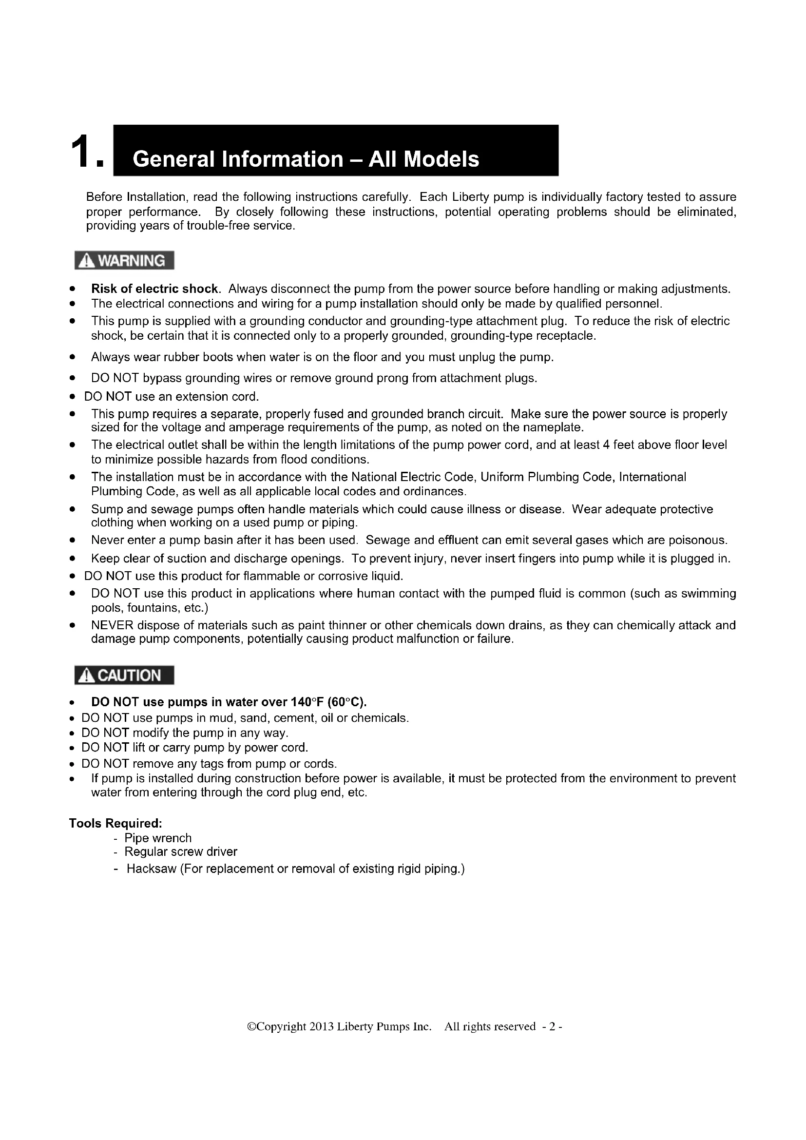
WARNING
- Risk of electric shock. Always disconnect the pump from the power source before handling or making adjustments.
- The electrical connections and wiring for a pump installation should only be made by qualified personnel.
- This pump is supplied with a grounding conductor and grounding-type attachment plug. To reduce the risk of electric shock, be certain that it is connected only to a properly grounded, grounding-type receptacle.
• Always wear rubber boots when water is on the floor and you must unplug the pump. - DO NOT bypass grounding wires or remove ground prong from attachment plugs.
• DO NOT use an extension cord. - This pump requires a separate, properly fused and grounded branch circuit. Make sure the power source is properly sized for the voltage and amperage requirements of the pump, as noted on the nameplate.
- The electrical outlet shall be within the length limitations of the pump power cord, and at least 4 feet above floor level to minimize possible hazards from flood conditions.
- The installation must be in accordance with the National Electric Code, Uniform Plumbing Code, International Plumbing Code, as well as all applicable local codes and ordinances.
- Sump and sewage pumps often handle materials which could cause illness or disease. Wear adequate protective clothing when working on a used pump or piping.
- Never enter a pump basin after it has been used. Sewage and effluent can emit several gases which are poisonous.
- Keep clear of suction and discharge openings. To prevent injury, never insert fingers into pump while it is plugged in.
- DO NOT use this product for flammable or corrosive liquid.
- DO NOT use this product in applications where human contact with the pumped fluid is common (such as swimming pools, fountains, etc.)
- NEVER dispose of materials such as paint thinner or other chemicals down drains, as they can chemically attack and damage pump components, potentially causing product malfunction or failure.
CAUTION
• DO NOT use pumps in water over 140°F (60°C).
- DO NOT use pumps in mud, sand, cement, oil or chemicals.
- DO NOT modify the pump in any way.
- DO NOT lift or carry pump by power cord.
- DO NOT remove any tags from pump or cords.
- If pump is installed during construction before power is available, it must be protected from the environment to prevent water from entering through the cord plug end, etc.
Tools Required:
- Pipe wrench
- Regular screw driver
- Hacksaw (For replacement or removal of existing rigid piping.)
2. Sump Pit – All Models
- A sump pit not less than 14" in diameter is recommended. On submersible pumps equipped with the vertical float (models 237 and 247), a minimum 10" diameter pit is acceptable. A larger diameter pit is preferred as it allows for longer pump cycling and reduced switch cycling. The depth of the pit should be at least 12" above the surface that the pump is resting on.
- If the pit is not already enclosed on the bottom, provide a hard level bottom of bricks or concrete. DO NOT place the pump directly on earth, gravel or debris since this can cause excessive wear of the impeller and possible jamming. "The Brick" (sold by Liberty Pumps as part # 4445000) is a pre-molded stable platform designed to fit your submersible pump. It raises the pump 2.5" off the bottom of the pit, reducing the potential for jamming from rocks and debris. Contact your local distributor to order. Remove all debris from the bottom of the sump pit before installation of the pump. A sump pit cover is suggested for safety and to prevent foreign objects from entering the pit.
3. Installation of Pump – All Models
1. Removal of Old Pump:
WARNING Disconnect pump from power source before handling.
Separate the discharge pipe at either the check valve or at the union. If neither a check valve nor a union is part of the existing discharge pipe, cut the pipe with a hacksaw and remove the pump (A union or check valve will need to be installed at this cut).
- Set the new pump in place making sure the float switch has adequate clearance and will not hang-up on the pit wall. The float must be free to move throughout its travel and not contacting the pump body, piping, or other objects.
- A 1-1/2" threaded discharge is provided on the pump for connection to the discharge pipe. Do not reduce the discharge size to less than 1-1/4", as this will affect pump flow and performance. Schedule 40 PVC pipe is recommended; however, flexible discharge hose kits may be used for temporary installations.
- Connect the pipe or the discharge hose to the discharge of the pump. HAND TIGHTEN ONLY. Overtightening may cause the pump housing to crack.
- Install a union or other means of separating the discharge pipe just above the floor to facilitate removal of the pump if necessary. A check valve is recommended just above or in place of the union to prevent the backflow of water after each pump cycle.
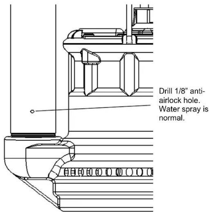
- If a check valve is used, a 1/8" anti-airlock hole should be drilled in the discharge pipe just above the pump's discharge outlet to prevent pump "airlock". Refer to Figure B.
text_image
Drill 1/8" anti- airlock hole. Water spray is normal.Figure A.
Is my pump air-locked? What is an anti-airlock hole?
Air-lock is a term used to describe when air gets trapped in the volute/impeller area of a pump and cannot escape due to the water column above the check valve on the discharge line. When the pit fills with water and the pump is called to activate, the impeller spins in this pocket of air and cannot prime. "My pump runs, but does not pump anything" is the symptom when this happens. An anti-airlock hole allows this trapped air to escape, allowing the pump to prime and start pumping.
Liberty provides an integral anti-airlock hole in the volute housing of submersible pumps. Water spray from this hole is normal while the pump is in operation. Bleeding off the air could take from several seconds to more than a minute once the pump starts. To speed or assist with air bleed in the event of airlock, the addition of a 1/8" hole in the discharge pipe is recommended. This hole should be no more than 1/8" diameter and drilled low on the pipe – just above the threaded connection to the pump discharge. See Figure A above.
-
Connect additional pipe as necessary to direct the discharge to the desired location. Discharge should be kept as short as possible with a minimum number of turns. Check all connections for security.
-
For added protection, consider the addition of a back-up pump such as Liberty's SJ10 SumpJet, as well as an alarm such as Liberty's ALM-2 in applications where loss of pump function could result in property damage. If an alarm is used, it must be connected to a separate electrical circuit.
-
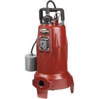
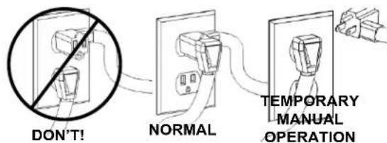
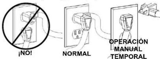
Models 243, 233, and 453 come factory-equipped with a float switch mounted to the pump. This model has two cords - one to the float switch and the other to the pump motor. The switch cord has a series (piggyback) plug enabling the pump (motor) cord to be plugged into the back of it (see Fig. at right). The purpose of this design is to allow temporary manual operation of the pump if desired.
Fig. 1 Piggyback plug installation.
text_image
DON'T! NORMAL TEMPORARY MANUAL OPERATION- For switchless models: Switchless models may be operated by directly plugging into an approved electrical outlet. To prevent excessive seal wear and overheating, pumps should not be run dry for extended periods of time. A minimum 4-1/2" water level is recommended. If manual models are to be used with an optional control device, follow the instructions provided with that control and make power connections per those instructions. Set the turn-off level at 4-1/2" or greater. Do not remove float rods from VMF models for manual use, as switch damage will result.
4. Trouble-Shooting
WARNING
Always disconnect the pump from power source before handling. This guide is designed
to help identify reasons for potential operating problems. It is not a service guide. Dismantling of pump voids warranty. Servicing of pump other than simple cleaning of pump inlet or impeller should be referred to the factory or its authorized service centers.
NOTE: The manufacturer assumes no responsibility for damage or injury due to disassembly in the field.
PUMP DOES NOT RUN OR HUM.
- Line circuit breaker may be off, tripped or loose. Have certified electrician check fuse or breaker.
- Water level in pit may be too low to activate switch. Add more water to pit.
- Plug on power cord may not be making contact in receptacle. Check security and connection.
- If the pump is using the series (piggyback) cord plug, the plugs may not be connected tightly together.
- Float may be obstructed. Make sure float is free and not interfering with the pit wall or other obstruction.
- If all symptoms check OK, the motor winding may be open. Consult factory.
PUMP RUNS OR HUMS BUT DOES NOT DELIVER WATER.
- Check valve may be installed backwards or is defective. Check to make sure it is installed properly and flapper in valve is free to move.
- Discharge line may be blocked or frozen. Check to see if line passes through cold areas or is blocked.
- Pump may be air-locked. Make sure that an anti-airlock hole was drilled in discharge pipe. Submersible models are factory equipped with a bleed hole already in base of pump. Ensure that this hole is not plugged.
- Vertical lift may be beyond pumps capability. See chart below for your pump's maximum lift capability.
NOTE: At the pump's maximum lift there will be no flow.
MODEL MAX. LIFT
| 230-Series | 21' |
| 240-Series | 20' |
| 450-Series | 34' |
- Check to see if inlet screen of pump is plugged or the impeller is jammed. Remove the pump screen and clean inlet and impeller as needed.
- Pump Impeller may be jammed. Check for foreign material such as construction debris, stones, etc. that might be preventing the impeller from rotating. Reminder: Make sure pump is disconnected from power source before checking inlet and impeller area.
PUMP RUNS AND REMOVES WATER BUT DOES NOT SHUT OFF.
- Float is stuck in the "on" position. Check to make sure the float is free to move up and down without obstruction.
- Switch may be defective. Consult factory.
PUMP RUNS BUT DELIVERS VERY LITTLE WATER.
- Vertical lift is approaching the pump's maximum lift capability. Refer to the above maximum lift chart above.
- Pump's inlet is partially blocked. Check to make sure the inlet is clear of debris.
- Discharge line is partially blocked. Check line for blockage.
- Check valve is not opening all the way. Check for defective, reversed, or blocked check valve.
CIRCUIT BREAKER TRIPS OR FUSE BLOWS WHEN PUMP STARTS.
- Fuse or breaker size is too small.
-
Other major appliances are on the same circuit. Pump should be on its own circuit.
-
Pump is connected to an extension cord or wiring is inadequate. Have an electrician check for proper wiring.
- Motor or switch may be defective. Consult factory.
PUMP SPRAYS WATER FROM SIDE OF HOUSING.
- This is normal due to factory drilled air-bleed hole and is not cause for concern.
5.
Maintenance
- Submersible Models: Submersible pump models have sealed permanently lubricated bearings and require no additional lubrication.
Pump should be checked frequently for debris and/or build up which may interfere with pump or float switch operation. The float must be able to move freely through its complete travel without any restrictions. Pour enough water into the sump to activate the pump periodically (at least every 3 months) when not normally in use to verify proper function. Check periodically to make sure the pit is free from accumulated debris, rocks or other objects that may potentially jam the pump.
6.
3 Year Limited Warranty
Liberty Pumps, Inc. warrants that pumps of its manufacture are free from all factory defects in material and workmanship for a period of 3 years from the date of purchase. The date of purchase shall be determined by a dated sales receipt noting the model and serial number of the pump. The dated sales receipt must accompany the returned pump if the date of return is more than 3 years from the "CODE" (date of manufacture) number noted on the pump nameplate.
The manufacturer's obligation under this Warranty shall be limited to the repair or replacement of any parts found by the manufacturer to be defective, provided the part or assembly is returned freight prepaid to the manufacturer or its authorized service center, and provided that none of the following warranty-voiding characteristics are evident.
The manufacturer shall not be liable under this Warranty if the product has not been properly installed; if it has been disassembled, modified, abused or tampered with; if the electrical cord has been cut, damaged or spliced; if the pump discharge has been reduced in size; if the pump has been used in water temperatures above the advertised rating, or water containing sand, lime, cement, gravel or other abrasives; if the product has been used to pump chemicals or hydrocarbons; if a non-submersible motor has been subjected to excessive moisture; or if the label bearing the serial, model and code number has been removed. Liberty Pumps, Inc. shall not be liable for any loss, damage or expenses resulting from installation or use of its products, or for consequential damages, including costs of removal, reinstallation or transportation.
There is no other express warranty. All implied warranties, including those of merchantability and fitness for a particular purpose, are limited to three years from the date of purchase.
This Warranty contains the exclusive remedy of the purchaser, and, where permitted, liability for consequential or incidental damages under any and all warranties are excluded.
Liberty Pumps
7000 Apple Tree Avenue
Bergen, NY 14416
Phone: (800) 543-2550
Fax: (585) 494-1839
www.libertypumps.com
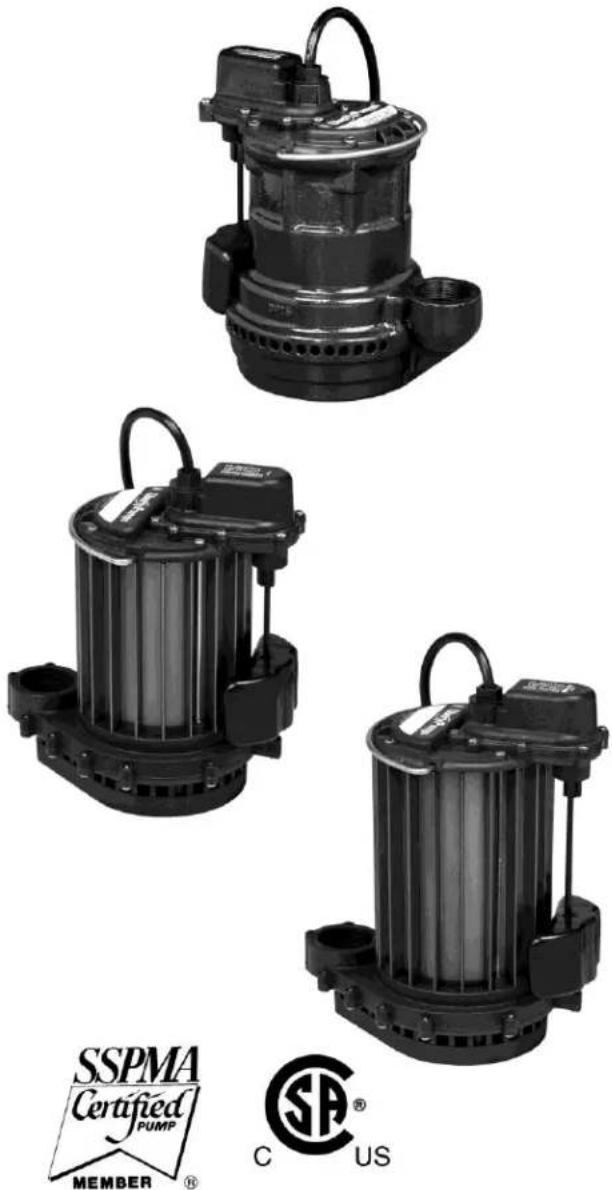
natural_image
Three black industrial pumps with visible internal components and mounting brackets (no text or symbols)

Fig. 1 Piggyback plug installation.
natural_image
Three black industrial pumps with visible internal components and mounting brackets (no text or symbols)