
Memoirs K1418 - Bathtub KOHLER - Free user manual and instructions
Find the device manual for free Memoirs K1418 KOHLER in PDF.

| Product Type | Built-in Hydromassage Bathtub |
| Brand | Kohler |
| Model | Memoirs K1418 |
| Power Supply | 208-240 V, 20 A, 50/60 Hz, dedicated circuit with GFCI or ELCB |
| Installation Type | Built-in or alcove, on leveled floor |
| Main Functions | Hydromassage Flexjets, back jets, neck jets, effervescence, chromotherapy |
| Control | Illuminated keypad with rotary ring and floating waterproof remote control (AAA batteries) |
| Heating | Integrated water heater, maintains up to 40°C (104°F), automatic shutdown beyond |
| Chromotherapy | 8 colors (white, purple, blue, aquamarine, green, yellow, orange, red), automatic cycle or manual selection |
| Electrical Safety | Mandatory grounding, disconnect before maintenance, GFCI/ELCB protection required |
| Maintenance and Cleaning | Mild soap and warm water, avoid abrasives; stubborn stains: turpentine |
| Spare Parts and Repairability | Service by Kohler authorized technician; pump, control, keypads, remote control, O-rings |
| Warranty | Kohler manufacturer warranty (details in manual) |
Frequently Asked Questions - Memoirs K1418 KOHLER
User questions about Memoirs K1418 KOHLER
0 question about this device. Answer the ones you know or ask your own.
Ask a new question about this device
Download the instructions for your Bathtub in PDF format for free! Find your manual Memoirs K1418 - KOHLER and take your electronic device back in hand. On this page are published all the documents necessary for the use of your device. Memoirs K1418 by KOHLER.
USER MANUAL Memoirs K1418 KOHLER
Drop-In Bath Whirlpool
K-1110K-1338 K-1339
natural_image
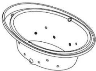
Line drawing of a bowl with perforated rim and circular indentations (no text or symbols)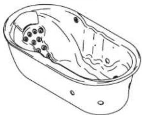
natural_image
Line drawing of a bathtub with internal organs and no text or symbols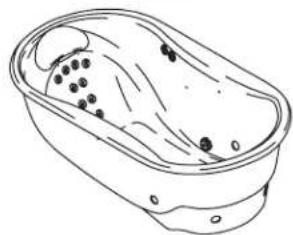
natural_image
Line drawing of a bathtub with black dots inside and liquid flowing out (no text or symbols)K-1375 K-1418 K-1457
natural_image
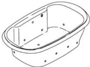
Line drawing of a rectangular basin with no text or symbols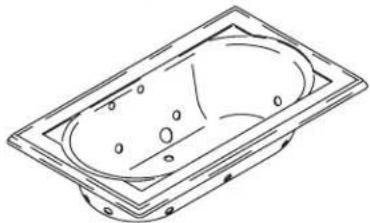
natural_image
Line drawing of a rectangular basin with circular indentations and mounting holes (no text or symbols)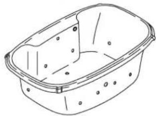
natural_image
Line drawing of a rectangular basin with circular indentations and a flat top (no text or symbols)Mproduct numbers are for Mexico (i.e. K-12345M)
WARNING: When using electrical products, basic precaution should always be followed, including the following:

DANGER: Riskofelectricshock. Connect only to circuits protected by a Ground-Fault Circuit-Interrupter (GFCI) or Earth-Leakage Circuit-Breaker (ELCB).
Building materials and wiring should be routed away from the pump body and other heat-producing components of the unit.
Install to permit access for servicing.
A pressure wire connector marked "Earth/Ground" is provided within the wiring compartment. To reduce the risk of electric shock, connect this connector to the grounding terminal of your electric service or supply panel with copper wire equivalent in size to the circuit conductor supplying this equipment.
Pressure wire connectors are provided on the exterior of the junction box or control within this unit to permit connection of a bonding conductor between this unit and all other exposed metal in the vicinity, as needed to comply with local requirements.
Grounding is required. The unit should be installed by a qualified service representative, and grounded.

WARNING: Riskofelectricshock. A licensed electrician should make all electrical connections.

WARNING: Riskofelectricshock.Disconnect power before servicing.

WARNING: Riskofinjuryorpropertydamage. Please read all instructions thoroughly before beginning installation, including the following requirements.
NOTICE: Followallocalplumbingandelectricalcodes.
Product Information
Electrical Requirements
The installation must have a Class A Ground-Fault Circuit-Interrupter (GFCI) or Earth-Leakage Circuit-Breaker (ELCB). The GFCI or ELCB protect against line-to-ground shock hazard. Use a 208 - 240 V, 20 A,50/60Hz dedicated service forthewirlpool.
Product Notices

WARNING: Unauthorized modification may cause unsafe operation and poor performance of the whirlpool. Do not relocate the whirlpool pump, or make other modifications to the whirlpool system, as this could adversely affect the performance and safe operation of the whirlpool. Kohler Co. shall not be liable under its warranty or otherwise for personal injury or damage caused by any such unauthorized modification.
Features
"CT" Relax Package: Components include a pump, heater, control, effervescence ports, chromatherapy lights and illuminated keypad with remote control.
"AH" Spa Package: Components include a pump, whirlpool jets, heater, control, effervescence ports, chromatherapy lights and illuminated keypad with remote control.
"V" Spa/Massage Package: Components include a pump, heater, control, backjet system, neckjet system, whirlpool jets, effervescence ports, chromatherapy lights and illuminated keypad with remote control.
"H2" and "M" Massage Package: Components include a pump, heater, control, backjet system, neckjet
Product Information (cont.)
system, whirlpool jets and illuminated keypad with remote control.
Connections and Service Access
Before installation, ensure proper access to the final connections.
NOTICE: Provide generous, unrestricted service access to the pump. You must provide access for servicing the pump and controls. The access must be located immediately next to the pump. Study the roughing-in information packed with the whirlpool.
Table of Contents
Important Information 2
Product Information 2
Electrical Requirements 2
Product Notices 2
Features 2
Connections and Service Access 3
Before You Begin 4
Tools and Materials 4
Prepare the Site 5
Prepare the Site 6
Prepare the Whirlpool 6
Secure the Whirlpool to the Subfloor 7
Cut the Pump Banding Straps 8
Install the Plumbing 8
Make Electrical Connections 9
Install the Whirlpool Trim Kit 10
Install the Neckjet Pillow (if Equipped) 10
Test Run the Whirlpool 10
Complete the Finished Wall/Deck 12
Complete the Concrete Installation 12
Clean-Up After Installation 12
Confirm Proper Operation 13
Operating Sequence 13
Neckjet and Backjet Operation (if Equipped) 14
Effervescence Operation (if Equipped) 14
Chromatherapy Operation (if Equipped) 14
Remote Control Operation 15
Troubleshooting Procedures 15
Before You Begin

CAUTION: Riskofproductdamage. Do not lift the whirlpool by the piping or pump, or use the piping or pump for structural support of the whirlpool.
☐ We recommend this whirlpool for drop-in or alcove installation.
□ Inspect the whirlpool for damage before you begin installation.
☐ You must install this whirlpool to an adequately supported, level subfloor.
☐ Confirm adequate support for a rim-mounted faucet; large faucets that may be inadvertently used as a means of support are not appropriate or safe for this installation.
☐ Kohler Co. reserves the right to make revisions in the design of products without notice, as specified in the Price Book.
Tools and Materials

Silicone Sealant Measuring Tape Pencil Level
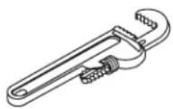
Safety Glasses Pipe Wrench
Plus:
- Conventional woodworking or concrete installation tools and materials
- Drop cloth
Whirlpool may be installed next to the wall or as an island installation.
Install an access panel to allow the pump to be serviced.
1. Prepare the Site
Concrete Construction
NOTICE:Adequate floor support must be provided. Consult the roughing-in sheet packed with your whirlpool for specific floor loading requirements.

CAUTION: Riskofproductdamage. Do not support the whirlpool by the rim.
☐ Make sure the flooring offers adequate support for your whirlpool, and verify that the subfloor is flat and level.
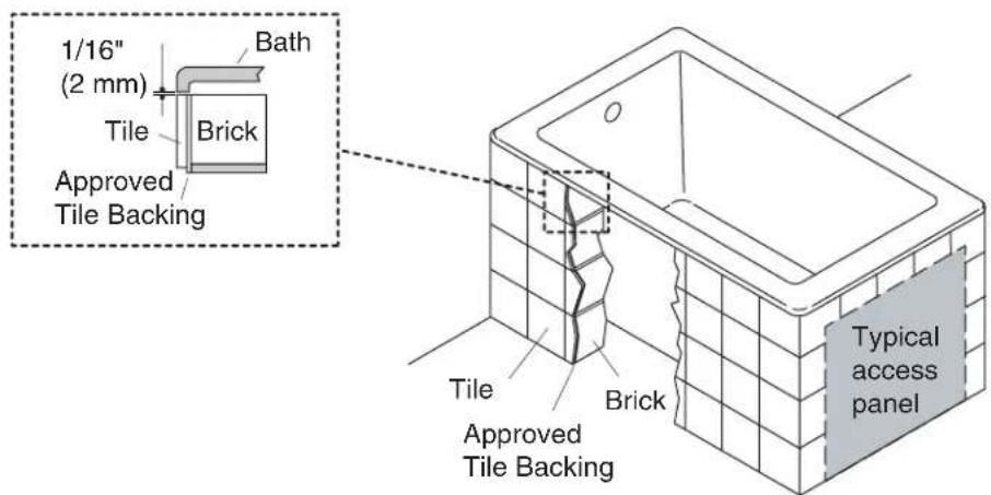
☐ This whirlpool may be installed next to the wall or in an island installation. An island installation requires a four side surround. In both instances, make sure the deck is supported by brick or concrete.
☐ Install an access panel to allow the pump to be serviced.
□ Construct brick or concrete supports.
☐ Provide a 1/16"(2 mm) gap between the whirlpool rim and the concrete or brick framing. Frame the floor, or construct a frame for a raised installation, in accordance with the roughing-in information packed with the whirlpool.
☐ Position the plumbing according to the roughing-in information packed. Cap the supplies, and check for leaks.
Position the rough plumbing.
Verify that the subfloor offers adequate support, and is flat and level.
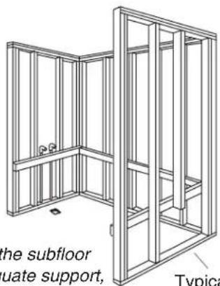
Construct 2x4 stud framing according to the roughing-in information.
Typical access panel
Position the rough plumbing.
Frame the floor according to the roughing-in information.
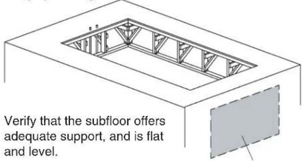
Typical access panel
2. Prepare the Site
Wood Construction
NOTICE:Adequate floor support must be provided. Consult the roughing-in sheet packed with your whirlpool for specific floor loading requirements.

CAUTION: Riskofproductdamage. Do not support the whirlpool by the rim.
☐ Make sure the flooring offers adequate support for your whirlpool, and verify that the subfloor is flat and level.
☐ The whirlpool may be used in a drop-in or alcove installation. Construct 2×4 stud framing designed for your particular installation. Frame the floor, or construct a frame for a raised installation in accordance with the roughing-in information packed with the whirlpool.
□ Use the roughing-in cut-out information to carefully lay out and cut the rough deck material.
□ Install an access panel to allow the pump to be serviced.
☐ Position the plumbing according to the roughing-in information. Cap the supplies, and check for leaks.
3. Prepare the Whirlpool
☐ We recommend a tiling-in bead for straight-rimmed whirlpools, if one or more sides of the whirlpool contact a wall. This bead prevents water from seeping between the whirlpool rim and the wall. Follow the instructions packed with the tiling-in bead to install the bead now.
- Install the drain to the whirlpool according to the drain manufacturer's instructions. Do not connect the trap at this time.
☐ Position a clean drop cloth or similar material in the bottom of the whirlpool. Be careful not to scratch the surface of the whirlpool.
Apply a bead of silicone sealant around the entire rim
or
Apply construction adhesive to the support blocks.
natural_image
Pure technical line drawing of a curved mechanical part without any text, numbers, or symbols4. Secure the Whirlpool to the Subfloor

CAUTION: Riskofproductdamage. Do not lift the whirlpool by the piping or pump, or use the piping or pump for structural support of the whirlpool.
☐ Choosetheinstallationoptionthatbestappliestoyourparticularinstallation.Followthe appropriateinstructions.
☐ If the subfloor is not level, shim the whirlpool support blocks as necessary.
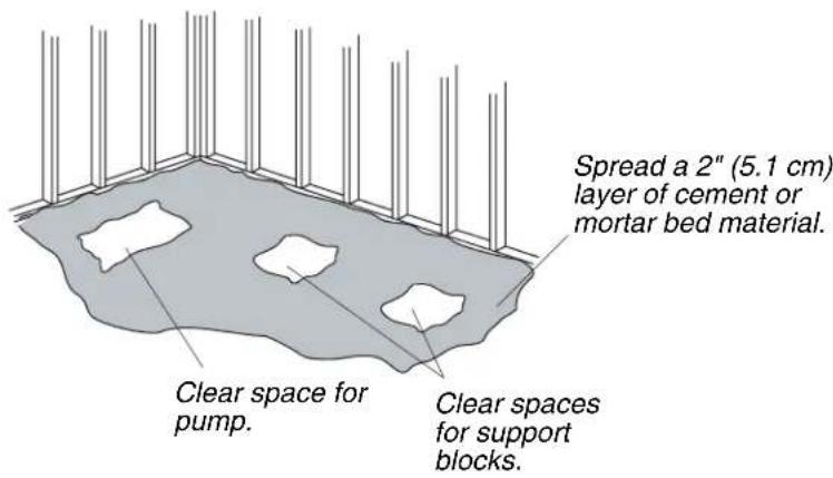
Option for Using a Cement or Mortar Bed
☐ Spread a 2" (5.1 cm) thick layer of cement or mortar on the subfloor where the whirlpool will be set. This will help secure, level, and support the unit. Clear all the material away from the pump control and support block locations.
NOTE: Do not use gypsum cement or drywall compound for this application, as they will not provide an acceptable, durable bond.
NOTE: The pump control (when the pump banding straps are cut) and support blocks must rest directly on the subfloor.
☐ Position a piece of plastic drop cloth material on top of the cement or mortar bed. With help, carefully lift the whirlpool into place, and make sure the pump control and support blocks do not rest in the bed material.
☐ Insert the drain tailpiece into the trap. Make sure the whirlpool is level and resting on all support blocks.
Option for Using Construction Adhesive
□ Apply a generous amount of high-quality construction adhesive to the bottom of the support blocks. With help, carefully lift the whirlpool into position.
☐ Insert the drain tailpiece into the trap. Make sure the whirlpool is level and resting on all support blocks.
Option for Using Silicone Sealant
□ With help, carefully lift the whirlpool into position.
☐ Insert the drain tailpiece into the trap. Make sure the whirlpool is level and resting on all support blocks.
□ Apply a continuous bead of high-quality silicone sealant around the entire rim of the whirlpool.
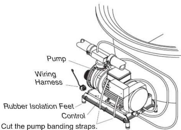
5. Cut the Pump Banding Straps
IMPORTANT!ThisstepisnecessarytomakeyourKohlerwhirlpooloperatemorequietly.
☐ Use tin snips to cut the two pump banding straps from the whirlpool pump.
NOTE: Do not raise the pump higher than it was before you cut the pump banding straps. If the pump is raised too high, it will not prime properly. Make sure the rubber isolation feet are in place.
☐ To minimize whirlpool noise and vibration, be sure the pump is not in direct contact with the shipping bracket after the pump banding straps are cut. The pump control contains rubber isolation feet to reduce pump noise.
6. Install the Plumbing

CAUTION: Riskofpropertydamage. Ensure a watertight seal on the whirlpool drain.
- Connect the drain to the trap according to the drain manufacturer's instructions.
NOTICE: An access panel will simplify future maintenance.
- Install the faucet valving according to the faucet manufacturer's instructions. Do not install the faucet trim until instructed. Open the hot and cold water supplies, and check the supply connections for leakage.
□ Run water into the whirlpool, and check the drain connections for leakage.
☐ If your whirlpool requires grip rails, install them now according to the installation instructions packed with the grip rails.
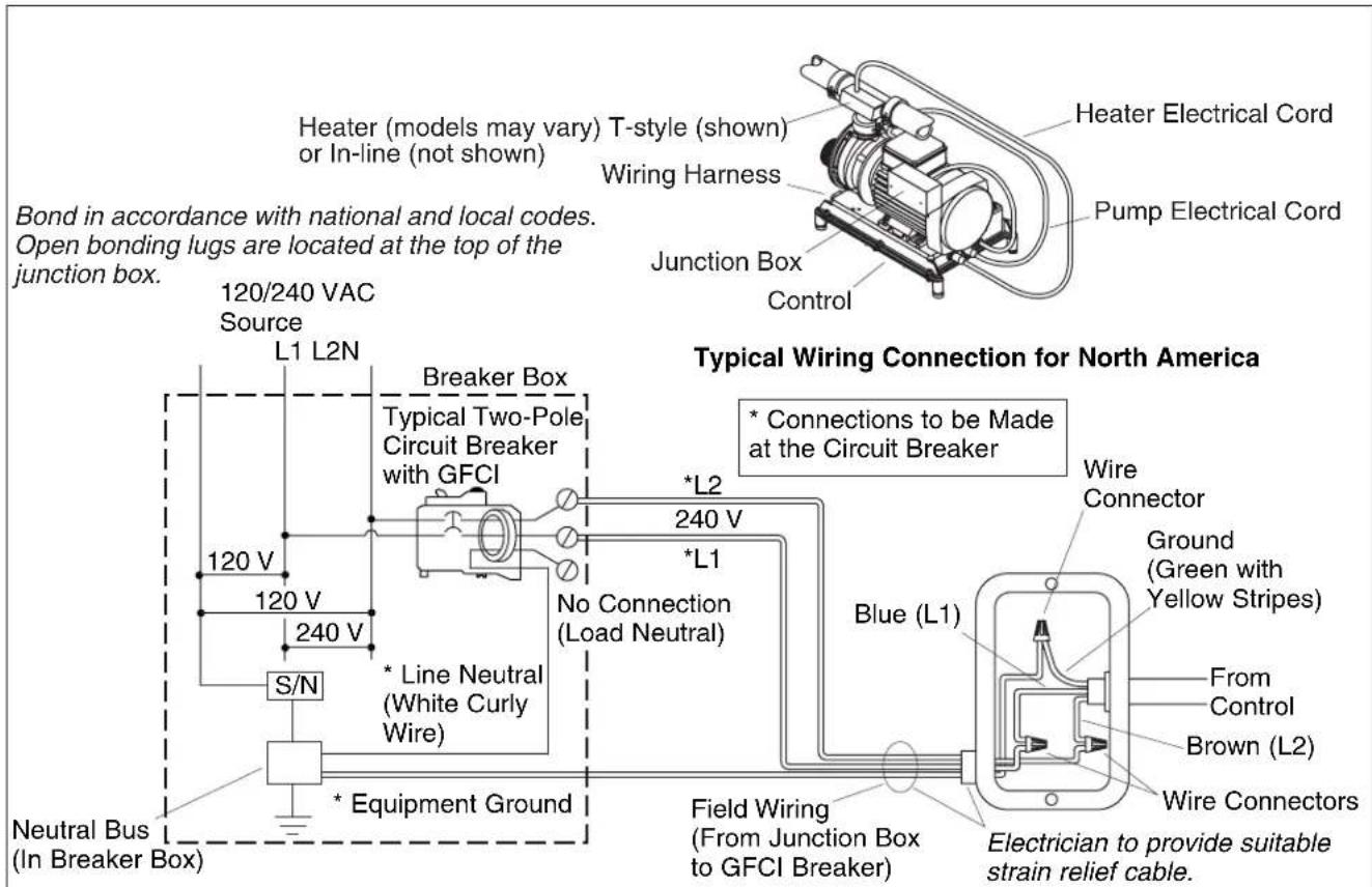
7. Make Electrical Connections
NOTE: The product model number is printed on a label on the pump side of the whirlpool bath. This label also identifies the electrical rating of the product. All whirlpools come equipped with a wiring junction box and are designed to operate between 208 VAC and 240 VAC at either 50 Hz or 60 Hz.

WARNING: Riskofelectricalshock. Make sure the power has been disconnected before performing the following procedures. Refer to the "Important Information" section.

WARNING: Risk of electrical shock. To reduce the risk of electrical shock, connect the pump to a properly grounded Ground-Fault Circuit-Interrupter (GFCI) or Earth-Leakage Circuit-Breaker (ELCB). This will provide additional protection against line-to-ground shock hazard. A 208-240 V, 20 A, 50/60 Hz dedicated circuit is required.
IMPORTANT! The load neutral is not used. There should be no connection to the load neutral terminal on the Ground-Fault Circuit-Interrupter (GFCI) breaker. The green wire with the yellow stripe is the equipmentgroundand needs to be connected to the neutral bus in the main circuit breaker box.
☐ The whirlpool bath control and system have been pre-wired at the factory. A licensed electrician should make a routine service connection to the junction box.
- Connect service to the junction box. The junction box contains blue, brown, and green with a yellow stripe colored wires.
□ Follow local electrical codes. Bond in accordance with national and local codes.
☐ A wiring harness has been pre-wired at the factory, allowing communication between the keypad, all features, and the control. No additional wiring is required, but ensure that all wires are securely fastened.
NOTE: Your wiring harness included an antenna for the optional remote control. Do not alter or damage this antenna during installation.
8. Install the Whirlpool Trim Kit
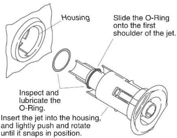
☐ Install the whirlpool trim kit according to the instructions packed with the trim kit. Pay particular attention to the jet installation steps below - they are very important and are included here to help you obtain smooth, trouble-free jet operation.
NOTE: The jet O-ring must be correctly positioned, must be lubricated, and must be in good condition to permit easy rotation and proper operation of the jet.
☐ Install the O-ring onto the first shoulder of the jet. Lubricate the O-ring with silicone lubricant to prevent noisy operation of the jet.
□ Carefully insert the jet into the housing, and lightly push and rotate the jet until it snaps into position. Donotforcethejet.
NOTE: When installed correctly, the jet should turn smoothly both clockwise and counterclockwise.
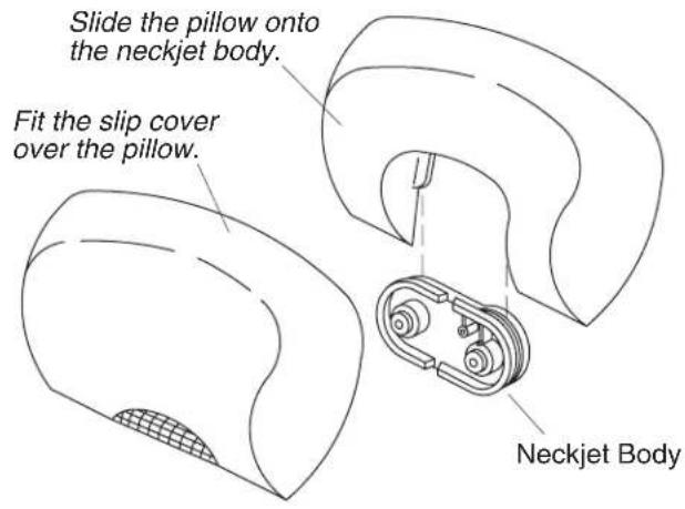
9. Install the Neckjet Pillow (if Equipped)
☐ The whirlpool is supplied with one pillow and two slip covers. The pillow includes a built-in magnetic reed switch. The neckjets will not operate unless the pillow is installed. Always use a slip cover to prevent water from spraying from the whirlpool.
☐ Choose a slip cover, and fit it over the pillow.
□ Carefully slide the pillow down onto the neckjet body grooves until it is secure. The neckjets are now ready for use.
☐ We recommend periodic cleaning of the slip cover. Follow the cleaning instructions on the label attached to the slip cover.
10. Test Run the Whirlpool
☐ Check all electrical connections, and make sure the electrical power to the whirlpool is turned on.
☐ Make sure all union connections to the pump and heater are securely hand tightened.
☐ Verify that the pump banding straps have been cut, and that the pump control is resting directly on the subfloor. Ensure that the rubber isolation feet are in place.
☐ Fill the whirlpool until the water level sensors (if equipped) are submerged. If your whirlpool does not have sensors, fill the whirlpool to a level at least 2^(5.1 cm) above the highest jet.
☐ Operate the whirlpool for 5 minutes (refer to the "Operating Sequence" section) and check all whirlpool piping connections, on the back side, for leaks.
Test Run the Whirlpool (cont.)
Turn on each of the whirlpool features and verify proper function. Check for any water leakage on the whirlpool's back side.
☐ Turn on the chromatherapy cycle and allow it to sequence through all eight colors; white, violet, indigo blue, aqua blue, green, yellow, orange and red. It takes approximately 1 minute to cycle through all eight colors.
- Verify functions using the remote control. Refer to "Remote Control Operation" section.
☐ For additional information on whirlpool operation, see "Confirm Proper Operation" section.
Drop-In Installation
11. Complete the Finished Wall/Deck
☐ If you have not already done so, carefully remove the protective tape from the whirlpool rim.
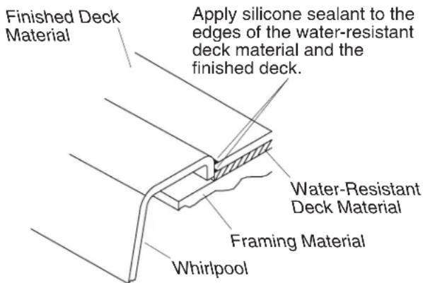
☐ Cover the framing with water-resistant wall/deck material. Seal the joints between the whirlpool rim edge and the water-resistant wall/deck material with silicone sealant.
☐ Tape and mud the water-resistant wall/deck material. Install the finished wall/deck to the water-resistant wall/deck material. Seal the joints between the whirlpool rim and the finished wall/deck material with silicone sealant.
□ Install the faucet trim according to the instructions packed with the trim.
12. Complete the Concrete Installation
☐ If you have not already done so, carefully remove the protective tape from the whirlpool rim.
□ Apply mortar and tile to the wall, deck and surround material as needed.
□ Apply a bead of sealant where the tile meets the whirlpool surface.
□ Install the faucet trim according to the instructions packed with the trim.
13. Clean-Up After Installation
☐ When cleaning up after installation, do not use abrasive cleansers, as they may scratch and dull the whirlpool surface. If necessary, use warm water and a liquid detergent to clean the surface of the whirlpool, user keypad and remote control.
☐ Remove stubborn stains, paint, or tar with turpentine or paint thinner. Donotallowcleaners containingpetroleumdistillatestoremainincontactwithanywhirlpoolsurfacesforlongperiods oftime.Remove plaster by carefully scraping with a wood edge. Do not use metal scrapers, wire brushes, or other metal tools. Use a powder-type detergent on a damp cloth to provide mild abrasive action to any residual plaster.
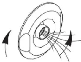
Turn the jet trim
clockwise to
decrease the flow.
natural_image
Diagram of magnetic field lines around a solenoid (no text or labels)Turn the jet trim counterclockwise to increase the flow.
14. Confirm Proper Operation
FilltheWhirlpool
NOTE: Please read these steps carefully before you operate your whirlpool.
☐ Turn the jet trim rings fully counterclockwise. Position the jet nozzles so they face down toward the basin.
☐ Fill the whirlpool until the water level sensors (if equipped) are submerged. If your whirlpool does not have sensors, fill the whirlpool to a level at least 2^7(5.1 cm) above the highest jet.
NOTE: The water temperature in the whirlpool should not exceed 104^ F ( 40^ C). The heater will automatically turn off as the water temperature approaches 104^ F ( 40^ C) and will remain off until the water cools.
15. Operating Sequence
NOTE: A built-in heater automatically helps to maintain the water temperature when the whirlpool is running, as long as the water temperature does not exceed 104^ F ( 40^ C). The heater will disengage at higher temperatures.
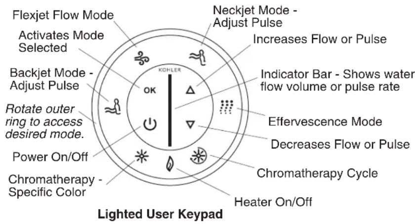
IMPORTANT! Please refer to your Homeowners Guide for detailed instructions on the user keypad and optional remote control.
NOTE: The keypad above shows features for all models. Your keypad may vary based on your whirlpool model.
- Press the Power On/Off button to turn on the whirlpool. The whirlpool will start at medium flow.
☐ Increase or decrease the water flow by pressing either the up or down arrow buttons on the keypad. An indicator bar in the center of the keypad shows the water flow volume.
☐ Adjust each jet for optimum air/water mixture. Turn the jet trim clockwise to reduce the air flow, and counterclockwise to increase the air flow.
☐ Rotate the outer ring until the heater button is flashing. Press "OK" to turn the heater off. Press "OK" again to turn the heater back on. The heater will help to maintain the water temperature up to 104^ F ( 40^ C).
☐ Press the Power On/Off button a second time to turn the whirlpool off.
NOTE:A built-in timer automatically stops the pump and motor after approximately 20 minutes of operation.
16. Neckjet and Backjet Operation (if Equipped)
☐ Make sure the slip cover is in place on the pillow, and the pillow is attached to the neckjet body.
NOTE: If the pillow is not properly installed the neckjets will stop. The neckjet icon and indicator bar on the user keypad will flash. The neckjets will automatically restart when the pillow is properly installed.
☐ With the whirlpool operating, rotate the outer ring until the neckjet icon is flashing. Press "OK" to activate the neckjets. The neckjet pulsing action will start at medium speed.
☐ To increase or decrease the neckjet pulsing action, press either the up or down arrow buttons on the keypad, while the neckjet mode is active.
☐ To increase or decrease the flow volume to the neckjets, rotate the outer ring to the Flexjet mode, press "OK" to activate the mode, and press either the up or down arrows on the keypad. This also increases or decreases the flow to all modes.
☐ Rotate the outer ring until the backjet mode is flashing and press "OK". The backjet pulsing action will start at medium speed. The backjets pulse from the bottom of the whirlpool toward the top, with water flow and pulse action occurring from two backjets at a time.
NOTE: If the water level falls below the water level sensors, the backjets will stop. The backjet icon and indicator bar on the user keypad will flash. The backjets will automatically restart when the water level covers the sensors.
☐ To increase or decrease the backjet pulsing action, press either the up or down arrow buttons on the keypad, while the backjet mode is active.
☐ To increase or decrease the flow volume to the backjets, rotate the outer ring to the Flexjet mode, press "OK" to activate the mode, and press either the up or down arrows on the keypad. This also increases or decreases the flow to all modes.
NOTE: To activate or deactivate different modes while the neckjets and/or backjets are operating, rotate the outer ring until the desired mode is flashing and press "OK". (Example: To turn the heater off, rotate the ring until the heater icon is flashing and press "OK").
- Press "OK" while the neckjet mode is flashing, to turn off the neckjets.
- Press "OK" while the backjet mode is flashing, to turn off the backjets.
17. Effervescence Operation (if Equipped)
☐ With the whirlpool operating, rotate the outer ring until the effervescence icon is flashing. Press "OK" to activate the effervescence ports. The effervescence action will start at the flow volume last set in the Flexjet flow mode.
☐ Increase or decrease the flow volume by pressing either the up or down arrow buttons on the keypad.
NOTE: The effervescence mode is intended to be a relaxing, soothing experience. The Flexjet mode, backjets and neckjets will automatically turn off when the effervescence mode is activated. Chromatherapy may be used with this and all modes of operation.
- Press "OK" while the effervescence mode is flashing, to turn off the effervescence ports.
18. Chromatherapy Operation (if Equipped)
NOTE: Chromatherapy may be used with all modes of operation. Chromatherapy may also be used when the pump is not operating.
☐ ChromatherapyCycle: When this mode is activated, the chromatherapy lights will automatically and continuously cycle through the eight colors; white, violet, indigo blue, aqua blue, green, yellow, orange and red. One cycle through all eight colors takes approximately one minute. Rotate the outer ring to select this mode and press "OK" to activate it. Press "OK" while the chromatherapy mode is active, to turn off the lights.
Chromatherapy Operation (if Equipped) (cont.)
☐ ChromatherapySpecificColorSelection: When this mode is activated, you may choose a specific color for the bath. Rotate the outer ring to select this mode, press "OK" to activate and use the up/down arrows to reach the desired color. Press "OK" while the chromatherapy mode is active, to turn off the lights.
19. Remote Control Operation
NOTE: Refer to your Homeowners Guide for detailed instructions on your remote control.
☐ The remote control places the whirlpool functions at your fingertips. You may access and modify all modes/features from the remote control. The waterproof remote control is designed to be used in the bath and will float in the water. The remote control uses two AAA batteries.
☐ The mode selector button functions in the same way as the outer ring. When "M" is pressed, one of the modes will flash on the user keypad. If "M" is pressed again, the next mode in clockwise order will flash. When the desired mode is flashing, press "OK" to activate it.
☐ When the Flexjet mode is active, the arrows will increase or decrease the water flow volume. When the neckjet or backjet mode is active, the arrows will increase or decrease the neckjet or backjet pulse speed.
20. Troubleshooting Procedures
This troubleshooting guide is for general aid only. A Kohler Authorized Service Representative or qualified electrician should correct all electrical problems. For warranty service, contact your dealer or wholesale distributor.
TroubleshootingtheWhirlpoolSystem
| SymptomsProbableCausesRecommendedAction | ||
| 1.User keypad does not illuminate when power button is pressed or outer ring is rotated. | A.No power to control. A.Check wiringB.GFCI or ELCB tripped. B.Reset GFCIC.Wiring harness from user keypad to control is loose, disconnected or damaged.D.User keypad does not work.E.Control does not work. | and connect power.or ELCB.C.Check wiring for proper connections. Replace wiring harness if necessary.D.Replace user keypad.E.Replace control. |
| 2.Motor starts, but all jets are not functioning. | A.Jet is closed.B.Jet not installed correctly.C.Jets are blocked. | A.Rotate jet trim counterclockwise to open.B.Reinstall jet; check for O-ring damage.C.Remove blockage. |
| 3.User keypad is illuminated, but does not respond to buttons or outer ring. | A.Control program is locked.B.Wiring harness from user keypad to control is loose, disconnected or damaged.C.User keypad does not work.D.Control does not work. | A.Reset GFCI or ELCB.B.Check wiring for proper connections. Replace wiring harness if necessary.C.Replace user keypad.D.Replace control. |
| 4.User keypad indicator bar keeps scanning at power-up. | A.Control program is locked. | A.Reset GFCI or ELCB. |
| Troubleshooting Procedures (cont.) | ||
| SymptomsProbableCausesRecommendedAction | ||
| B.Wiring harness from user keypad to control is loose, disconnected or damaged.C.User keypad does not work. C.Replace user keypad.D.Control does not work. D.Replace control. | B.Check wiring for proper connections. Replace wiring harness if necessary. | |
| 5.User keypad is illuminated, but pump won't start. | A.Power cord from pump to control is loose, disconnected or damaged.B.Pump does not work. B.Replace pump.C.Control does not work. C.Replace control. | A.Check wiring for proper connections. |
| 6.Motor runs but pump won't prime (cavitates). | A.Pump is shimmed too high. A.Lower pump/control to subfloor level.B.Small air leak at pump inlet. B.Securely tighten nut(s) on intake side of pump.C.Motor/pump does not work. C.Replace motor/pump.D.Control does not work. D.Replace control. | |
| 7.Pump stops before 18 minutes. | A.GFCI or ELCB tripped. A.Identify source of fault, and correct. Reset GFCI or ELCB.B. Suction is blocked.C.Jets are blocked.D.Motor overheated and protection device activated. | B. Remove obstruction.C.Remove blockage.D.Check for blockage at suction and/or jets. Remove blockage and allow motor to cool. |
| 8.Pump does not automatically stop after 22 minutes. | A.20-minute timer inadvertently disabled. | A.See service manual. |
| 9.Pump won't turn off when the power button on user keypad is pressed. | A.User keypad does not work. A.Replace user keypad.B.Control does not work. B.Replace control. | |
| 10. Pump operates but variable speed feature does not work. | A.Motor/pump does not work. A.Replace motor/pump.B.Control does not work. B.Replace control. | |
| 11. Bath water cools while pump is operating. | A.Water temperature above 104°F (40°C).B.Heater is turned off on user keypad.C.Wiring from heater to control is loose, disconnected or damaged.D.Heater does not work.E. Control does not work. | A.Allow bath water to cool.B.Turn heater on.C.Check wiring for proper connections.D.Replace heater.E. Replace control. |
| 12. Noisy operation. | A. Pump banding straps have not been cut.B.Dry or dislodged jet O-ring (squeal). | A.Cut pump banding straps with tin snips.B.Remove jet, replace and lubricate O-ring, and reinstall jet. |
| 13. Remote control (if equipped) does not work. | A.Batteries improperly installed or dead.B.Antenna on wiring harness is damaged.C.Remote control not programmed correctly.D. Remote control does not work. | A.Replace batteries.B.Replace wiring harness.C.See homeowners guide or service manual.D. Replace remote control. |
| E.Control does not work. E.Replace control. | ||
| TroubleshootingtheNeckjetSystem | ||
| SymptomsProbableCausesRecommendedAction | ||
| 14.Keypad does not respond when neckjet mode is selected. | A.User keypad does not work. A.Replace user keypad. | |
| 15.Pump operates but neckjets do not turn on. Indicator bar on user keypad is flashing. | A.Pillow is not installed. A.Make sure the pillow is properly attached to the neckjet body.B.Reed switch does not work. B.Check reed switch wiring and replace if necessary.C.Wiring harness from neckjet to control is loose, disconnected or damaged. | |
| 16.Pump operates but neckjets do not turn on. Indicator bar on user keypad is NOT flashing. | A.Neckjet line is blocked. A.Disconnect neckjet hoses and remove blockage.B.Wiring harness from neckjet to control is loose, disconnected or damaged.C.Butterfly valve does not work. C.Replace butterfly valve.D.Control does not work. D.Replace control. | |
| 17.Water flows from neckjets, but neckjets do not pulse. | A.Wiring harness from neckjet pulse cannister to control is loose, disconnected or damaged.B. Pulse cannister does not work.C.Control does not work. C.Replace control. | |
| TroubleshootingtheBackjetSystem | ||
| SymptomsProbableCausesRecommendedAction | ||
| 18. Backjets do not operate. | A. Whirlpool pump is not operating.B.Backjet butterfly valve does not open.C. Not enough water in whirlpool.D. Actuator switch does not work.E.Power from pump motor to control is off.F. Backjet pipe is blocked.G.Switch wire from switch to control is disconnected. | A.Turn on pump.B.Check for loose connections or wires leading from backjet pulse cannister to control. Replace backjet pulse canister or control if necessary.C. Fill whirlpool so water level sensors are covered.D. Replace actuator switch.E.Check for loose connections or wires leading from pump motor to control.F. Remove blockage.G.Reconnect or replace switch wires that use modular plug. |
| 19. Backjets do not pulse. | A. Pulse cannister does not work.B.Switch does not work.C.Switch wire from switch to control is disconnected. | A. Check for loose connections or wires leading from pulse cannister to control. Replace pulse canister or control if necessary.B.Replace switch.C.Reconnect or replace switch wires that use modular plug. |
| TroubleshootingtheEffervescenceJets | ||
| SymptomsProbableCausesRecommendedAction | ||
| 20.Effervescence ports do not work. | A.Whirlpool pump is not operating.B.Butterfly valve does not work. B.Replace butterfly valve.C.Pump does not work. C.Refer to the service manual to troubleshoot the system. Refer to installer/dealer.D.Control does not work. D.Replace control. | A.Turn on pump. |
| 21.Effervescence ports do not bubble. | A.Air intake on suction line is blocked.B.Water flow is too low. B.Increase water flow. | A.Remove blockage. |
| TroubleshootingtheChromatherapyLights | ||
| SymptomsProbableCausesRecommendedAction | ||
| 22.Chromatherapy lights do not work. | A.Loose, disconnected or damaged wiring/connections.B.Control does not work. B.Replace control. | A.Check wiring for proper connections. Replace wiring if necessary. |
natural_image
Pure line drawing of a curved mechanical part with no text, numbers, or symbolsnatural_image
Diagram of magnetic field lines around a solenoid with arrows indicating direction (no text or labels)natural_image
Pure technical line drawing of a curved mechanical part with no text or symbolsnatural_image
Diagram of a mechanical or fluid system with concentric circular layers and directional arrows indicating flow or force (no text or symbols)
- Drop-In Bath Whirlpool
- Product Information
- Electrical Requirements
- Product Notices
- Features
- Product Information (cont.)
- Connections and Service Access
- Table of Contents
- Before You Begin
- Tools and Materials
- Plus:
- Prepare the Site
- Concrete Construction
- Prepare the Site
- Wood Construction
- Prepare the Whirlpool
- Secure the Whirlpool to the Subfloor
- Option for Using a Cement or Mortar Bed
- NOTE: The pump control (when the pump banding straps are cut) and support blocks must rest directly on the subfloor.
- Option for Using Construction Adhesive
- Option for Using Silicone Sealant
- Cut the Pump Banding Straps
- Install the Plumbing
- Make Electrical Connections
- Install the Whirlpool Trim Kit
- Install the Neckjet Pillow (if Equipped)
- Test Run the Whirlpool
- Test Run the Whirlpool (cont.)
- Complete the Finished Wall/Deck
- Complete the Concrete Installation
- Clean-Up After Installation
- Confirm Proper Operation
- Operating Sequence
- Neckjet and Backjet Operation (if Equipped)
- Effervescence Operation (if Equipped)
- Chromatherapy Operation (if Equipped)
- Chromatherapy Operation (if Equipped) (cont.)
- Remote Control Operation
- Troubleshooting Procedures
Brand : KOHLER
Model : Memoirs K1418
Category : Bathtub