
VTRB131 - Fan Infiniton - Free user manual and instructions
Find the device manual for free VTRB131 Infiniton in PDF.

| Product type | Ceiling fan |
| Brand | Infiniton |
| Model | VTRB131 |
| Dimensions | Blade diameter: 132 cm |
| Weight | Approximately 7 kg |
| Power supply | 220-240 V ~ 50 Hz |
| Motor power | 60 W |
| Number of speeds | 3 (low, medium, high) |
| Control | Pull chain or optional wall control |
| Reversing switch | Yes (summer/winter) |
| Light kit | Compatible (optional, not included) |
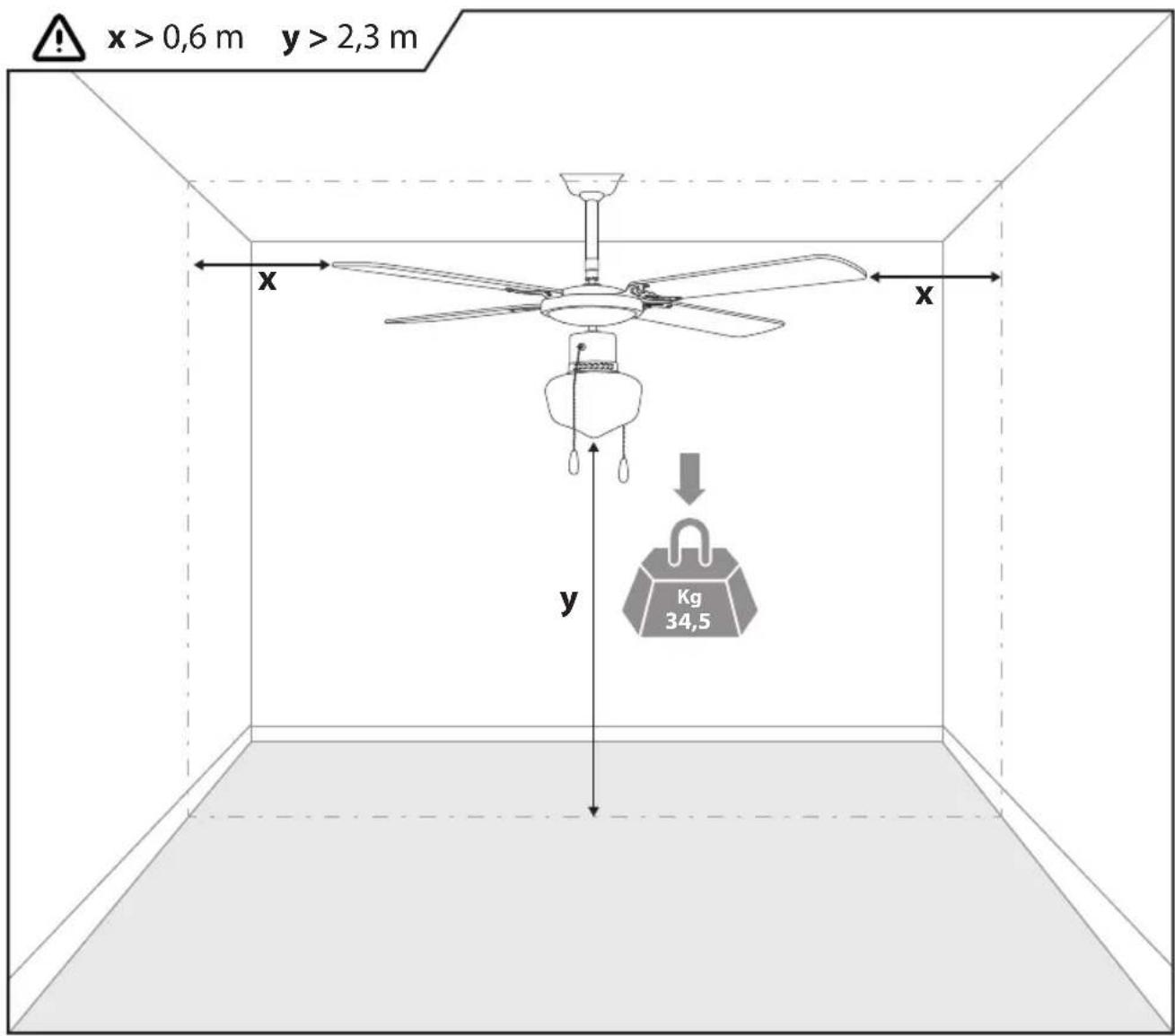
| Minimum installation height | 2.3 m between floor and blade edge |
| Required support capacity | Minimum 34.5 kg |
| Use | Indoor, dry rooms |
| Material | Metal and plastic |
| Cleaning | Dry or slightly damp cloth, no water or detergent |
| Safety circuit breaker | Required with 3 mm pole spacing |
| Warranty | Complies with current safety standards |
| Spare parts | Available from after-sales service |
Frequently Asked Questions - VTRB131 Infiniton
User questions about VTRB131 Infiniton
0 question about this device. Answer the ones you know or ask your own.
Ask a new question about this device
Download the instructions for your Fan in PDF format for free! Find your manual VTRB131 - Infiniton and take your electronic device back in hand. On this page are published all the documents necessary for the use of your device. VTRB131 by Infiniton.
USER MANUAL VTRB131 Infiniton
Installation instructions
natural_image
Line drawing of a five-petal ceiling fan with a hanging bulb and hanging blades (no text or symbols)ÍNDICE / INDEX / INDICE DE
PÁGINA/ PAGE
- INSTRUCCIONES DE INSTALACIÓN 1
- INSTALLATION INSTRUCTIONS 5
- INSTRUCTIONS D'INSTALLATION 9
- INSTRUÇÕES DE INSTALAÇÃO 13
- ADVERTENCIA / WARNING / AVERTISSEMENT / AVISO 17
- INSTRUCCIONES DE MONTAJE 18
ASSEMBLY INSTRUCTIONS
INSTRUCTIONS DE MONTAGE
CAUTION: We recommend the installation be performed by a qualified electrician who can check the strength of the supportive ceiling members and make proper electrical connections.
All wiring must be in accordance with national and local electrical codes and the ceiling fan must be grounded as a precaution against possible electrical shock.
An all-pole disconector with isolating distance of 3mm must be incorporated in the fixed wiring in accordance with the national wiring rules.
The product is in accordance with safety standards into force. Repairs should be exclusively performed by qualified technicians using original spare parts. Any breach of this instruction may be particularly dangerous for the users.
WARNING: Please be sure pivot pin and split pin are in place and both setscrews on downrod are tightened securely before operation.
To reduce the risk of fire or electric shock, do not use this fan with any solid-state speed control device.
IMPORTANT SAFETY PRECAUTIONS:
1) Check if the electrical specifications of the appliance are compatible with your installation.
2) Unauthorized use or technical modification to the appliance can lead to danger to life and health.
3) This appliance is not intended for use by persons (including children) with reduced physical, sensory or mental capabilities, or lack of experience and knowledge, unless they have been given supervision or instruction concerning use of the appliance by a person responsible for their safety.
4) This appliance is for indoor use only except moist or wet room.
5) Means for disconnection must be incorporated in the fixed wiring in accordance with wiring rules into force.
6) Before wiring the paddle fan, turn off the electric power supply at the main fuse box or main circuit breaker and leave it off until the installation is complete.
7) The outlet box and support structure must be securely mounted an capable of reliably supporting a minimum of 34,5 kgs. Use only metallic outlet boxes.
8) Do not install paddle fan less tan 2,3 between floor and lowest edge of fan blades. Check hanging location in order to assure adequate clearance with adjacent walls, furnitures, etc..
9) All wiring must be in accordance with the National Electrical Code and local electrical codes. Electrical installation should be performed by a qualified licensed electrician.
10) Do not operate reversing switch while fan blades are in motion. Fan must be turned off and blades stopped before reversing blade direction.
11) Avoid placing objects in the path of the blades.
12) Always disconnect the appliance before cleaning or doing maintenance. Do not use water or detergents when cleaning the fan or fan blades. In order to not damage the product, it is advisable to use adapted equipment to the fragile surfaces and products slowing the wear on the appliance. A dry dust cloth or lightly dampened cloth will be suitable for most cleaning.
13) After making electrical connections, spliced conductors should be turned upward and pushed carefully up into outlet box. The wires should be spread apart with the grounded conductor and the equipment-grounding conductor on one side of the outlet box.
14) The supplier disclaims all liability for personal injury or property damage arising from incorrect use or installation of the fan. In doubt, call upon an electrician.
15) Children should be supervised to ensure that they do not play with the appliance.
16) This appliance can be used by children aged from 8 years and above and persons with reduced physical, sensory or mental capabilities or lack of experience and knowledge if they have been given supervision or instruction concerning use of the appliance in a safe way and understand the hazards involved. Children shall not play with the appliance. Cleaning and user maintenance shall not be made by children without supervision.
ENVIRONMENTAL PROTECTION:
WARNING!
Electrical products must not be thrown out with domestic waste. They must be taken to a communacollecting point for environmentally friendly disposal in accordance with local regulations. Contact yourlocal authorities or stocklist for advice on recycling. The packaging material is recyclable. Dispose of thepackaging in an environmentally friendly manner and make it available for the recyclable material collection-service.
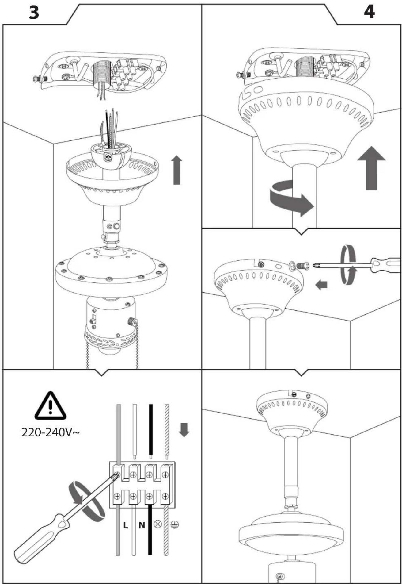
ASSEMBLING AND INSTALLATION:
1) Verify all parts against part list and diagram.
2) Remove motor from packing. To avoid damage to finish assemble motor on soft padded surface or use the original packaging in motor box.
3) It is essential that the outlet box or structural member from which the far is to be suspended will safely support the fan. In view of the torque and weight factors involved some outlet boxes will require additional strengthening by securing more firmly to Wood beams of steel supports.
4) Attach the mounting bracket to the outlet box with the screws provided. Attached canopy into hanging bracket with fan unit and ball joint hang below the canopy and secured with 4 setscrews.
5) Making sure the ball is properly seated with molded Groove engaged with the tab on canopy be certain that hanging ball is fully locked into position.
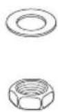
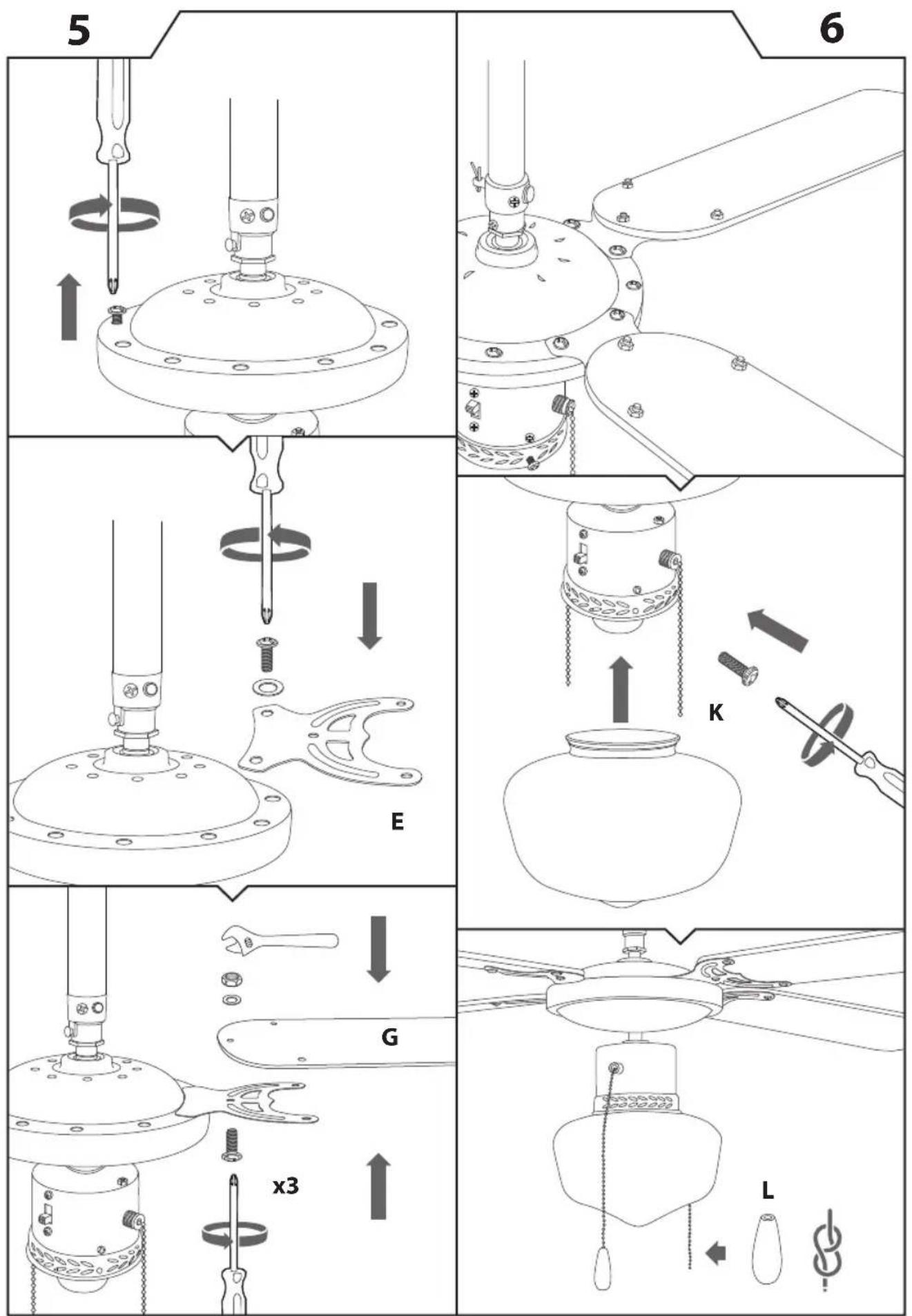
6) Attach blades to the blade brackets using screws, nuts and washers. The three screws per blade are protruded from bottom of the blade bracket, through the blade bracket into the blade. Then place the washer and nut on top of the screw, holding the nut, thread the screw to tighten the blade and the blade bracket. Repeat instruction for fixing all blades to blade brackets.
7) Secure the blades to the fan motor with screws and washers.
8) Make the power wire connections with wires black to black, white to white and green to green or bare wire(ground).Make sure that fan is properly grounded. Carefully push all wiring inside wiring box after splices are made. The blue wire is provided for the connection of optional light kit. Do not connect this wire if light is not installed.
OPERATING INSTRUCTIONS:
1) Turn on power and check operation of fan. The pull chain controls the fan as follows: One pull-high speed; two pulls-medium speed; three pulls-low speed; four pulls "OFF".
2) If regulator speed controls being applied, the regulator controls the fan as follows: Turn control knob to position "1" (slow speed), then increase as required ins steps to position "5" (full speed).
3) The slide switch controls "FOWARD" and "REVERSE". Be sure turn off the power source before reverse the fan.
Air Flow Direction Downward. Speed Medium to Full Speed. In warmer weather, your ceiling fan will let you reduce your use of air conditioning, keeping the air moving to help you cool.
Air Flow Direction Upward. Speed Low to Medium.
In cooler weather upward airflow reduces drafts while moving hotter air off the ceiling. The exact speed will depend on the size of the room, number of fan, ceiling height, etc.. It should be fast enough to break up the air stratification, but slow so as not to create a breeze.
ELECTRICAL CONNECTIONS:
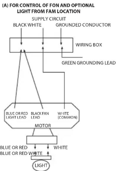
Connect black to live, white to neutral, and green grounding lead to the grounded conductor of the supply circuit. If you are installing a light kit, connect blue or red to live of the supply circuit. Use wire connectors provided with your fan.
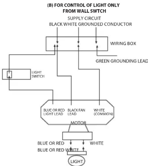
NO LOOSE STRANDS or LOOSE CONNECTIONS SHOULD BE PRESENT. After splices are made, the wires must be spread apart so that Green and White are on one side of the outlet box and the black (and blue or red if light kit is installed) are on the other side. Turn splices upward and carefully push hall wiring into outlet box. For optional wall controls, see Fig.8B, 8C, 8D. (Note: Regulator control fan speed only, cannot use in light kit.)
flowchart
graph TD
    A["CONTROL OF FON AND OPTIONAL LIGHT FROM FAM LOCATION"] --> B["SUPPLY CIRCUIT"]
    B --> C["BLACK WHITE"]
    B --> D["GROUNDED CONDUCTOR"]
    C --> E["WIRING BOX"]
    D --> E
    E --> F["GREEN GROUNDING LEAD"]
    F --> G["MOTOR"]
    G --> H["BLUE OR RED LIGHT LEAD"]
    G --> I["BLANCE LEAD"]
    G --> J["WHITE (COMMON)"]
    H --> K["WHITE"]
    I --> K
    J --> K
    K --> L["LIGHT"]
flowchart
graph TD
    A["Light SWITCH"] --> B["BLUE OR RED LIGHT LEAD"]
    A --> C["BLACK FAN LEAD"]
    A --> D["WHITE (COMMON)"]
    B --> E["MOTOR"]
    C --> E
    D --> E
    E --> F["WHITE"]
    E --> G["BLUE OR RED WHITE"]
    G --> H["LIGHT"]
    I["SUPPLY CIRCUIT"] --> J["BLACK WHITE GROUNDED CONDUCTOR"]
    K["WIRING BOX"] --> L["GREEN GROUNDING LEAD"]
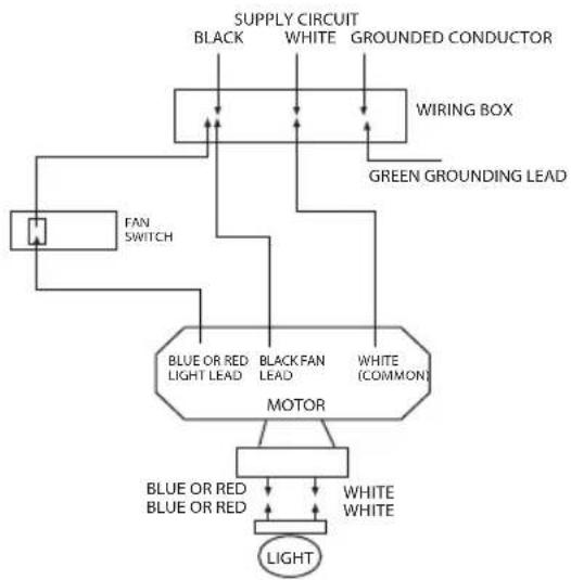
(C) FOR CONTROL OF FAN FROM WALL
flowchart
graph TD
    A["SPPLY CIRCUIT"] --> B["BLUE OR RED"]
    A --> C["BLUE OR RED"]
    A --> D["WHITE"]
    A --> E["WHITE (COMMON)"]
    F["GROUNDED CONDUCTOR"] --> G["WIRING BOX"]
    H["FAN SWITCH"] --> I["MOTOR"]
    J["LEAD"] --> I
    K["LEAD"] --> I
    L["LEAD"] --> I
    M["LEAD"] --> N["LIGHT"]
    O["LEAD"] --> P["WHITE"]
    Q["LEAD"] --> R["WHITE"]
    S["LEAD"] --> T["WHITE"]
    U["LEAD"] --> V["WHITE"]
    W["LEAD"] --> X["WHITE"]
    Y["LEAD"] --> Z["WHITE"]
    style A fill:#f9f,stroke:#333
    style F fill:#ccf,stroke:#333
    style H fill:#cfc,stroke:#333
    style J fill:#fcc,stroke:#333
    style O fill:#cff,stroke:#333
    style P fill:#ffc,stroke:#333
    style Q fill:#fcc,stroke:#333
    style R fill:#fcc,stroke:#333
    style S fill:#fcc,stroke:#333
    style T fill:#fcc,stroke:#333
    style U fill:#fcc,stroke:#333
    style V fill:#fcc,stroke:#333
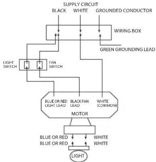
(D) FOR CONTROL OF FAN AND LIGHT FROM WALL
flowchart
graph TD
    A["Light SWITCH"] --> B["FAN SWITCH"]
    B --> C["MOTOR"]
    C --> D["BLUE OR RED LIGHT LEAD"]
    C --> E["BLACK FAN LEAD"]
    C --> F["WHITE (COMMON)"]
    C --> G["WHITE"]
    H["SUPPLY CIRCUIT"] --> I["BLACK"]
    H --> J["WHITE"]
    H --> K["GROUNDED CONDUCTOR"]
    L["WIRING BOX"] --> M["Green GROUNDING LEAD"]
    N["LIGHT"] --> O["White"]
    style A fill:#f9f,stroke:#333
    style C fill:#ccf,stroke:#333
    style D fill:#cfc,stroke:#333
    style E fill:#fcc,stroke:#333
    style F fill:#cff,stroke:#333
    style G fill:#ffc,stroke:#333
    style H fill:#fff,stroke:#333
    style I fill:#fff,stroke:#333
    style J fill:#fff,stroke:#333
    style K fill:#fff,stroke:#333
    style L fill:#fff,stroke:#333
    style M fill:#fff,stroke:#333
    style N fill:#fff,stroke:#333
    style O fill:#fff,stroke:#333
REPAIR GUIDE:
| TROUBLE PROBLEM CAUSE SUGGEST REMEDY | ||
| Fan will not start. • Fuse or circuit breaker blown. • Loose power lone connections to the fan. • Speed controller not in correct position. | • Check main and branch circuit fuses or circuit breakers. • Check line wire connections to fan. • Check speed controller's position. | |
| Fan sounds noisy. • Top canopy touching ceiling. • Loose fan blades screws. • Ceiling fan not secured against ceiling. • Incorrect speed controller. | • Lower canopy from ceiling to ensure minimum 3mm clearance. • Re-tighten all screws on fan blades but never o ver-tighten. • Re-tighten all screws in the hanging bracket or plate. • Change the controller to the one supplied. | |
| Mechanical noise. • Allow at least for 8 hours setting-in period. | ||
| Fan wobbles. • Fan blades are not horizontal to ceiling. • Blade screws are loose. | • Measure from ceiling to tips of blades, the rotate fan so all blades are checked for equal height from ceiling(not ajustments may be made by slight pressure up or down on blade holders). • Make sure all screws are securely fastened. | |
OTHERS:
1) Have your product repaired by a qualified person.
2) This electric product is in accordance with the relevant safety requirements. Repairs should Only be carried out by qualified persons using original spare parts; otherwise this may result in considerable danger to the user.
3) Please contact the store which you bought the product for after sale services if question.
natural_image
Symbolic illustration of a person running inside a circle with lightning bolts and a battery (no text or labels)
x > 0,6 m y > 2,3 m
natural_image
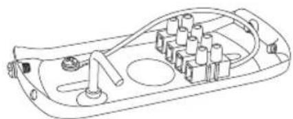
Technical line drawing of a mechanical device with mounting flange and wiring (no text or symbols)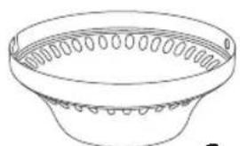
natural_image
Line drawing of a bowl with circular patterns on the rim (no text or symbols)C
natural_image
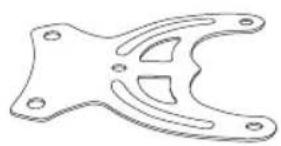
Technical line drawing of a mechanical bracket or clamp (no text or symbols)E
natural_image
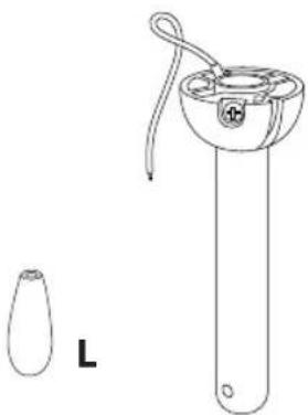
Line drawing of a laboratory apparatus with a test tube and a separate petri dish labeled L (no text or symbols on the diagram itself)B
natural_image
Technical line drawing of a mechanical component with no visible text or symbolsA
natural_image
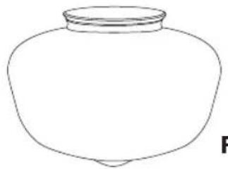
Simple line drawing of a ceramic jar with a lid (no text or symbols)F
natural_image
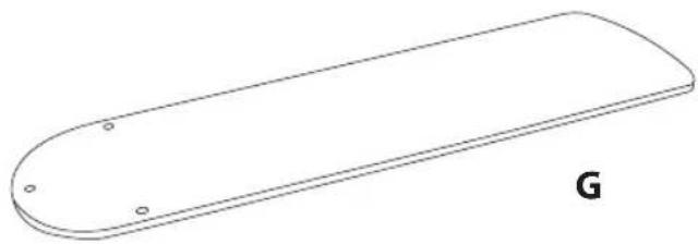
Simple line drawing of a rounded rectangular object with four circular holes, labeled 'G' at the bottom (no text or symbols on the object itself)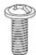
H

|
J
K

NOT INCLUDED / NON INCLUS / NÃO INCLUÍDO
NO INCLUIDO
natural_image
Line drawings of five different types of electrical tools: wrench, screwdriver, bulb, and bolt (no text or symbols)
SERVICIO TÉCNICO (SAT)
If you have any further questions about the device, please contact us at: info@infiniton.es
And on our website www.infiniton.es
You can also contact our official technical service (SAT) - MEGAEXIT, S.L
tel: (+34) 954 087 169
REPAIRS: rma@megaexit.com
www.megaexit.com
Summary of Declaration of conformity
INFINITON declares, under its responsibility, that this device complies with the provisions of Directive 99/05 / EC of the European Parliament and of the Council of March 9, 1999, transposed into Spanish legislation by means of Royal Decree 1890/2000, of 20 of November.
For more information related to declarations and certificates of conformity, please contact us at info@infiniton.es


Follow us on our social networks and access exclusive content

INFINITON

Brand : Infiniton
Model : VTRB131
Category : Fan