
IAN 345811 - Workbench PARKSIDE - Free user manual and instructions
Find the device manual for free IAN 345811 PARKSIDE in PDF.

| Product type | Workbench (height-adjustable trestle) |
| Brand | Parkside |
| Model | IAN 345811 |
| Maximum load capacity | 200 kg |
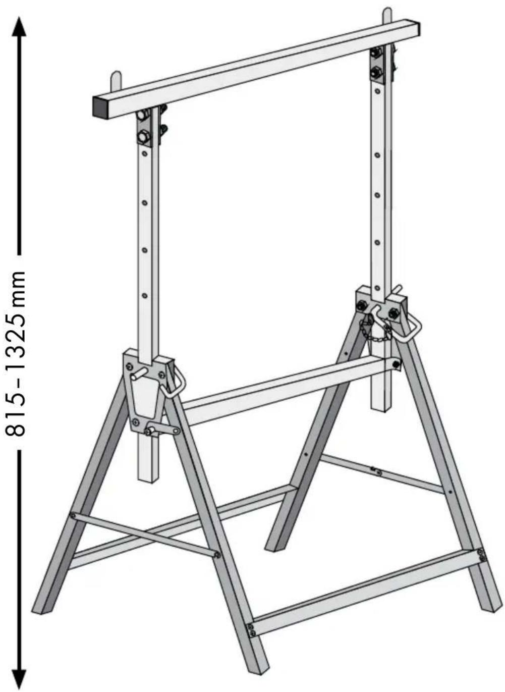
| Working height | Approx. 815 to 1325 mm (adjustable) |
| Weight | Approx. 6.26 kg |
| Material | Steel |
| Intended use | Private use as a work trestle to support workpieces or a worktop |
| Main functions | Height adjustment, foldable, spread protection |
| Included parts | 2 side parts, 2 lower struts, 2 hole rows, 1 support strut, 1 center strut, 2 safety pins, spread protection (long and short), safety support, screw kit |
| Height adjustment | By safety pin on hole row |
| Care and cleaning | Clean regularly with a dry, lint-free cloth. Do not use aggressive or corrosive products. |
| Safety instructions | Do not use as a ladder, do not exceed max. load, use on a flat and solid surface, always fully unfold legs and install protections, do not leave children unsupervised. |
| Storage | Fold legs and store in a dry, locked room. |
| Disposal | The packaging is recyclable. The used product must be disposed of at a local recycling center. |
| After-sales service | Keep the receipt and model number (IAN) as proof of purchase. |
Frequently Asked Questions - IAN 345811 PARKSIDE
User questions about IAN 345811 PARKSIDE
0 question about this device. Answer the ones you know or ask your own.
Ask a new question about this device
Download the instructions for your Workbench in PDF format for free! Find your manual IAN 345811 - PARKSIDE and take your electronic device back in hand. On this page are published all the documents necessary for the use of your device. IAN 345811 by PARKSIDE.
USER MANUAL IAN 345811 PARKSIDE
HEIGHT-ADJUSTABLE TRESTLE
GB IE NI
Assembly, operating and safety instructions
DK
H∅JDEJUSTERBARARBEJDSBUK
Before reading, unfold the pages containing illustrations and familiarise yourself with all functions of the device.
DK
GB/IE/NI Assembly, operating and safety instructions Page 5
Introduction......Page 6
Intended use....Page 6
Parts description an scope of delivery....Page 6
Technical data......Page 6
Safety instructions......Page 7
Installation Page 8
Use Page 8
Height adjustment....Page 9
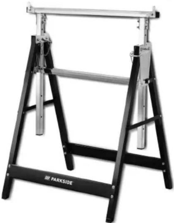
Height-adjustable trestle
- Introduction
We congratulate you on the purchase of your new product. You have chosen a high quality product. Familiarise yourself with the product before using it for the first time. In addition, please carefully refer to the operating instructions and the safety advice below. Only use the product as instructed and only for the indicated field of application. Keep these instructions in a safe place. If you pass the product on to anyone else, please ensure that you also pass on all the documentation with it.
Intendeduse
This product is suitable for private use as a trestle. Other uses or changes to the product are considered to be contrary to the intended use and may harbour risks of injury and damage. The manufacturer does not accept any liability for injury or damage resulting from use of this product contrary to its intended use. The product is not intended to be used for commercial purposes.
● Parts description an scope of delivery
1 2 x Flat head bolt, incl. 2 washers, nut, M5 x 12 mm
2 x Hex head bolt, incl. washer, nut M5 x 12 mm
3 8 x Round head bolt, incl. 2 washers, nut M6 x 35 mm
4 4 x Hex head bolt, incl. washer, nut M8 x 45 mm
5 2 x Side frame
6 2 x Bottom plate
7 2 x Hole bar
8 1 x Top support bar
9 1 x Middle support bar
10 2 x Locking pin
11 Locking hook, short
12 Locking hook, long
13 Safety bracket
Operating instructions
- Technical data
Load Capacity: max. 200 kg
Working height: approx. 815-1325 mm
Net weight: approx. 6.26 kg

Safety instructions
KEEP ALL SAFETY NOTICES AND INSTRUCTIONS IN A SAFE LOCATION!
WARNING! DANGER OF LOSS OF LIFE AND ACCIDENT TO INFANTS AND CHILDREN! Never leave children unsuper-
vised with the packaging materials. The packaging material presents a suffocation risk. Children frequently underestimate danger. Keep out of reach of children. This product is not a toy.
On delivery and prior to first use, inspect the product in order to check the condition and function of all parts. Do not use the product if it has been damaged. You risk injury if you do otherwise.
■ Do not use a damaged product.
CAUTION! Do not leave children unattended. The product is not a climbing frame or toy. Make sure that nobody climbs or leans on the product, particularly children. The product could become imbalanced and tip up. This may result in injury and/or damage.
CAUTION! RISK OF INJURY! Never use the product as a ladder or as anything else.

CAUTION! RISK OF INJURY! Never climb on the product or work surface.

Make sure that you never exceed the maximum permissible load (see "Technical data").

ke sure that the product is stable and cannot tip. Injuries or damage to the product can result.

CAUTION! CRUSHING HAZARD! Watch your fingers when opening and closing the product.

y use the product on firm, level surfaces. If used on unstable or uneven surfaces- e.g. gravel surfaces- the load can slip.

CAUTION! RISK OF INJURY! Absolutely do not use the product on subsurfaces that have slopes. The product, along with any workpieces on it, can tip over.

ure the legs are folded apart all the way and the locking hooks 11 12 are secured in place when using the product. This will ensure stability.

using the product if the leg lock, adjustment or the weld are damaged.

CAUTION! RISK OF INJURY! Make sure that the subsurface is not damp or oily. The product can slip and fall over.
- Verify the work pieces / sheet will not move on the top support bar 8. If necessary, secure in place.
■ Make sure that you do not load workpieces unevenly. Otherwise, the workpiece can become unbalanced and fall down.
■ Remove any excess materials on the product, e.g. wet paint, dirt, oil or snow.
■ When working, always use two trestles to hold the components / worktops.
Do not place a load on the product that protrudes over the side.
- Do not use this multi-purpose trestle as a scaffold trestle.
- Installation
Note: Make sure during assembly that the screws are only loosely tightened to begin with. Tighten the screws fully only after you have completely assembled the product.
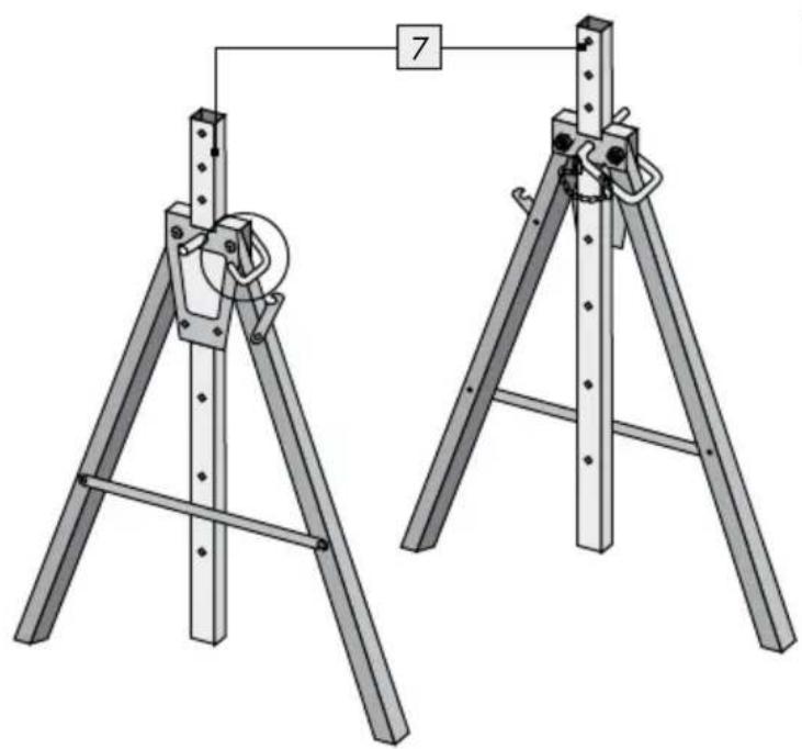
First spread the leg of side frame. Pull down the locking pin 10 on the leg and lock the locking hook 12 on the other leg. Insert the hole bar 7 through the middle part of side frame 5. Use the locking pin 10 and insert through the hole on the side frame 5 in order to lock the hole bar 7 in place. Please be reminded to leave at least 3 holes to be protrude on top of the frame. Repeat the above steps to have 2 side frames with support bar (Fig. A).
Make sure both hole bars are on the same height.
Connect the middle support box and use screw sets 1 and 2 to connect with both side frames 5 (Fig. B).
Use screw set on the side where is the locking hook 11 on the leg. After you finish connect screw set 2, pull down the locking hook 11 and lock the hooks on the screw. Use the screw sets 1 on the other side. Repeat the above steps to fix the middle support bar 9 in place (Fig. C).
Connect the bottom plate to the leg with screw set 3. Repeat the above to fix both bottom plates in place (Fig. D).
Place the top support bar onto the hole bar 7. Use screw sets 4 to fix the top support bar 8 in place (Fig. E).
Adjust the product correctly. Then retighten all screws.
Note: it is necessary to fasten the supporting struts 6 tightly to the legs to ensure that the torsional rigidity of the axle stand is good.
☐ Raise the two safety brackets on the top support bar 8 (Fig. F).
- Use
CAUTION! RISK OF INJURY! Be sure locking hooks 11 und 12 are secured in place. Also ensure that both trestles are always at the same height. This is the only way to ensure stability.
■ Always use two trestles and a board or boards together for working.
- Verify the work pieces/sheet will not move on the top. If necessary, secure in place. - Make sure that you do not load workpieces unevenly. Otherwise, the workpiece can become unbalanced and fall down.
☐ Fold the legs all the way apart.
- Verify the safety devices and adjustments are positioned correctly. - Place the work piece you will be working on on the top support button.
● Height adjustment
You can adjust the product's height using the security pin 10.
Remove all workpieces/the working board from the product.
Take out the locking p10. Adjust the hole bar 7 on both side to the desired working height.
☐ Insert the locking pin to lock the hole bar 7 in place.
- Cleaning und care
□ Clean the product with a dry, fluff-free cloth.
☐ Never use aggressive or corrosive cleaning agents, as they may damage the product.
●Storage
□ Having finished the work, unhook the two locking hook and 12 and fold the legs together.
Store the product in a dry place if you are not going to use it for a protracted period.
●Disposal
The packaging is made entirely of recyclable materials, which you may dispose of at local recycling facilities.
Contact your local refuse disposal authority for more details of how to dispose of your worn-out product.
●Service
Please have the receipt and item number (e.g. IAN 123456_7890) ready as your proof of purchase when making an enquiry.

G
Packaging from responsible sources
FSC® C144392
- HEIGHT-ADJUSTABLE TRESTLE
- H∅JDEJUSTERBARARBEJDSBUK
- DK
- INTRODUCTION......PAGE 6
- SAFETY INSTRUCTIONS......PAGE 7
- INSTALLATION PAGE 8
- USE PAGE 8
- INTRODUCTION
- INTENDEDUSE
- ● PARTS DESCRIPTION AN SCOPE OF DELIVERY
- TECHNICAL DATA
- SAFETY INSTRUCTIONS
- KEEP ALL SAFETY NOTICES AND INSTRUCTIONS IN A SAFE LOCATION
- WARNING! DANGER OF LOSS OF LIFE AND ACCIDENT TO INFANTS AND CHILDREN! NEVER LEAVE CHILDREN UNSUPER
- INSTALLATION
- USE
- ● HEIGHT ADJUSTMENT
- CLEANING UND CARE
- ●STORAGE
- ●DISPOSAL
- ●SERVICE
Brand : PARKSIDE
Model : IAN 345811
Category : Workbench