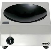
105840 - Cooker BARTSCHER - Free user manual and instructions
Find the device manual for free 105840 BARTSCHER in PDF.


| Product Type | Built-in hob with radiant elements |
| Brand | Bartscher |
| Model | 105840 |
| Number of cooking zones | 1 (standard model) |
| Control type | Rotary knob with 10 power positions |
| Dimensions (W x D x H) | 400 x 455 x 120 mm |
| Weight | 7.5 kg |
| Electrical supply | 230 V ~ 50/60 Hz, single-phase |
| Total power | 2.5 kW |
| Recommended fuse | 16 A |
| Protection class | IP 43 |
| Surface material | Glass ceramic |
| Main functions | Cooking, grilling, keep warm, flambé |
| Indicator lights | Green (power on), Red (residual heat) |
| Safety | Automatic shut-off, electric shock protection, residual heat indicator |
| Maintenance and cleaning | Industrial kitchen cleaner, non-abrasive sponge; do not use steel wool |
| Spare parts and repairability | Use original parts; repair by authorized personnel only |
| Installation environment | Operating temperature: +5°C to +35°C; relative humidity: 30% to 90% |
| General information | Compact modular design; installation on flat surface; power cord with plug |
Frequently Asked Questions - 105840 BARTSCHER
User questions about 105840 BARTSCHER
0 question about this device. Answer the ones you know or ask your own.
Ask a new question about this device
Download the instructions for your Cooker in PDF format for free! Find your manual 105840 - BARTSCHER and take your electronic device back in hand. On this page are published all the documents necessary for the use of your device. 105840 by BARTSCHER.
USER MANUAL 105840 BARTSCHER
natural_image
Exterior view of a portable electric stove with a black dome and control knob (no visible text or symbols)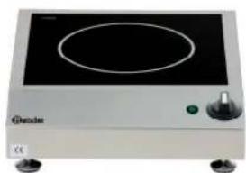
natural_image
Exterior view of a portable electrical appliance with a black top and control knob (no visible text or symbols)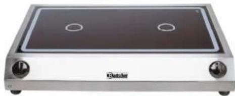
natural_image
Exterior view of a stainless steel electric stove with two circular vent holes (no text or symbols visible)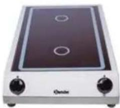
natural_image
Exterior view of a modern electric stove with two rotary switches (no visible text or symbols)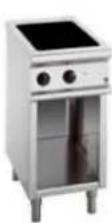
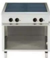
natural_image
Exterior view of a stainless steel kitchen appliance with dual control knobs and a solar panel (no text or symbols visible)105.840, A105.942, A105.943, A105.946, A105.948
A105.949, A105.952, A105.953, A105.954, A105.956, A105.957, A105.935, A105.936, A105.937, A105.938, A105.939
A105.950, A105.958, A105.968, 282.410, 282.420
Inhaltsverzeichnis
1 Allgemeines 3
1.1 Anwendung 3
A105.942, A105.943, A105.954, 282.410, 282.420,
BI-Modelle
A105.946, A105.948, A105.949, A105.952, A105.953, A105.956, A105.957
BW-Modelle
105.840, A105.935, A105.936, A105.937, A105.938
Position EIN:
Operation instructions for Induction Units
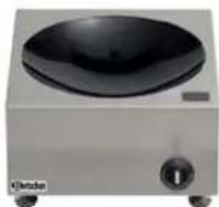
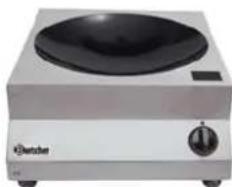
natural_image
Exterior view of a portable electric stove with a black dome and control knob (no visible text or symbols)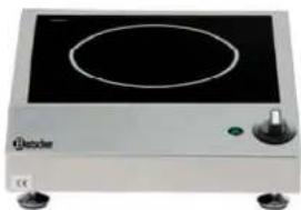
natural_image
Exterior view of a portable electrical appliance with a circular top and control knob (no visible text or symbols)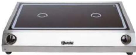
natural_image
Exterior view of a BTBSER electric stove with two circular vent holes (no text or symbols visible)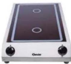
natural_image
Exterior view of a simple electric stove with two circular top outlets (no text or symbols visible)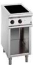
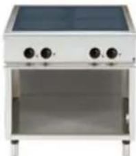
natural_image
Exterior view of a stainless steel kitchen appliance with four circular control knobs (no visible text or symbols)105.840, A105.942, A105.943, A105.946, A105.948
A105.949, A105.952, A105.953, A105.954, A105.956, A105.957
A105.935, A105.936, A105.937, A105.938, A105.939
A105.950, A105.958, A105.968, 282.410, 282.420
Contents list
1 General information 3
1.1 Area of application 3
2 Products description 3
2.1 Products 3
2.2 Technical Data 4
2.2.1. Operation and Control 4
2.2.2. Technical data 4
2.2.3. Function conditions 4
3 Installation
3.1 Electrical data of the Units 5 3.1.1. Unit Performance (2,5 kW, 3 kW) 5
3.1.2. Unit Performance (3,5 kW) 5
3.1.3. Unit Performance (5 kW) 5
3.1.4. Unit Performance (7 kW, 8 kW) 5
3.2 Installation requirements 6
3.3 Installation instructions 6
3.4 Additional Installation instructions for the built-in Model 6-7
4 Taking the Unit into Service 7
4.1 Unit Assembly 7-8
5 Function test 9
6 Operation 10
6.1 Cooking 10
7 Safety instructions 11
7.1 Description of warning symbols and indicators 11
7.2 Dangers resulting from not observing the safety instructions 11
7.3 safe Application 12
7.4 Operator Safety Instructions 12
7.5 Improper operation 13
7.6 Modification / use of spare parts 13
7.7 Pan detection 13
7.8 Heating zone monitoring 13
7.9 Noises 13
8 When the unit is not in use 13
9 Troubleshooting 14-16
9.1. Overview error messages on display 16
10 Cleaning 17
11 Maintenance 18
12 Disposal 18
13 Sparepartlist 19-21
1. General information
These operating instructions contain basic information on what needs to be considered during installation, operation, and maintenance of the equipment. They must be read entirely by the fitter and operators before the equipment is installed and taken into operation. They must always be kept close to the cooking site for reference.
1.1 Area of application
“Berner” cooking units have been designed for the preparation of meals. They can be used for cooking, keeping food warm, as well as for flambé singing, grilling, etc. Note: Only use pans suitable for induction cooking with these units. You should not use no-name products. The pan bottom must be magnetic. If in doubt, check with the help of a magnet.
2. Products description
2.1 Products
BM-Modelle
A105.942, A105.943, A105.954, 282.410, 282.420
BI-Modelle
A105.946, A105.948, A105.949, A105.952, A105.953, A105.956, A105.957
BW-Modelle
105.840, A105.935, A105.936, A105.937, A105.938
- Compact module design
- Easy installation
- service-friendly
- easy operation via power control knob
- compact high-performance electronics for easy and safe operation
- max. operation safety due to various protecting and control functions
- compact outside dimensions
- low weight
2.2 Technical Data
2.2.1 Operation and Control
Operation indicator lamp „Operation, Pan Detection“ 2V DC/ approx. 10mA (LED red)
Output regulator – potentiometer 0Ohm – 10kOhm
Digital display „Performance und Fault display“ 2,8V DC/ca. 60mA (red)
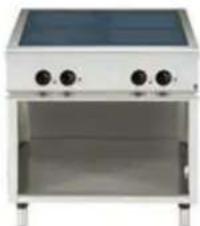
Dimensions W x D x H Ceramic glass surface
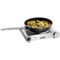
| 105.840 330 x 380 x 175 mm Wok glass bowl | |
| A105.942,.943,.954 340 x 420 x 100 mm 290 x 290 mm | |
| A105.946,.948,.949 400 x 455 x 120 mm 350 x 350 mm | |
| A105.956,.957 400 x 655 x 120 mm 350 x 560 mm | |
| A105.952,.953 700 x 455 x 120 mm 650 x 350 mm | |
| A105.935,.936,.937 400 x 455 x 180 mm Wok glass bowl | |
| A105.938 500 x 555 x 235 mm Wok glass bowl | |
| A105.950 400 x 400 mm 350 x 350 mm | |
| A105.958 400 x 700 mm 350 x 650 mm | |
| A105.968 700 x 700 mm 650 x 650 mm | |
| 282.410 | 400 x 700 x 860-900 mm 350 x 605 mm |
| 282.420 | 800 x 700 x 860-900 mm 650 x 605 mm |
2.2.2 Technical Data
| Unit | Voltage | Performance | Weight |
| 105.840 | 1 x 230 V | 3.0 kW | 8,5 kg |
| A105.942,.943,.954 | 1 x 230 V | 2.5, 3.0, 3,5 kW | 9 kg |
| A105.949 | 3 x 400 V | 5 kW | 13 kg |
| A105.946,A105.948 | 1 x 230 V | 3.0, 3.5 kW | 11-13 kg |
| A105.937 | 3 x 400 V | 5kW | 14 kg |
| A105.935,A105.936 | 1 x 230 V | 3.0, 3.5 kW | 11-13 kg |
| A105.938 | 3 x 400 V | 8 kW | 19 kg |
| A105.950 | 3 x 400 V | 5 kW | 12 kg |
| A105.958 | 3 x 400 V | 7, 10 kW | 21 kg |
| A105.968 | 3 x 400 V | 20 kW | 40 kg |
| 282.410 | 3 x 400 V | 10 kW | 50 kg |
| 282.420 | 3 x 400 V | 20 kW | 80 kg |
2.2.3 Function conditions
- max. tolerance of main voltage +5%/-10%
- frequency 50 / 60 Hz
- IP Code IP 43
- min. Pan-diameter 12cm
3 Installation
3.1 Electrical data of the Units
3.1.1. Unit Performance (2,5 kW, 3 kW)
Inductions unit 1-phase (Voltage 230 Volt +5% / -10%)
| Connection | Colour | Frequency | Fuse |
| Phase | Black | 50 Hz / 60 Hz | Empty |
| N | Blue | Working frequency22-35 kHz | Control fuse1 X 400mA T(time lag) |
| Ground | Yellow/Green |
3.1.2. Unit Performance (3,5 kW)
Inductions unit 1-phase (Voltage 230 Volt +5% / -10%)
| Connection | Colour | Frequency | Fuse |
| Phase | Black, Brown or 1 | 50 Hz / 60 Hz | 2 X 20A FF(super-quick) |
| N Blue or 2 | Working frequency22-35 kHz | Control fuse2 X 160mA T(time lag) | |
| Ground | Yellow/Green |
3.1.3. Unit Performance (5 kW)
Inductions unit 3-phases (Voltage 400 Volt +5% / -10%)
| Connection | Colour | Frequency | Fuse |
| Phase Black, Brown or 1, 2, 3 | 50 Hz / 60 Hz 3 | X 12,5A FF (super-quick) | |
| N Blue or 4 | Working frequency 22-35 kHz | Control fuse 2 X 100mA T (time lag) | |
| Ground | Yellow/Green | ||
3.1.4. Unit Performance (7 kW, 8 kW)
| Inductions unit 3-phases (Voltage 400Volt +5% / -10%) | |||
| Connection | Colour | Frequency | Fuse |
| Phase Black, Brown or 1, 2, 3 | 50 Hz / 60 Hz 3 | X 16A FF (quick) | |
| N Blue or 4 | Working frequency 22-35 kHz | Control fuse 2 X 100mA T (time lag) | |
| Ground | Yellow/Green | ||
Installations-environment
- max. ambient temperature
Storage >-20°C till +70°C
in Function >+5^ till +35^
- max. relative Atmospheric humidity
Storage > 10% till 90%
in Function > 30% till 90%
3.2 Installation requirements
The Induction-Unit has to be placed on a flat horizontal area. Don't cover the air supply for the air circulation. The place must be allowing a weight up to min. 40 kg. To disconnect the Power, the user needs easy access to the power-connection.
3.3 Installation instructions
The following Points must always be observed during installation:
Make sure that the main voltage corresponds to the voltage indicated on the nameplate of the equipment.
- All electric installations must fulfill the local building code regulations. All regulations issued by the national electricity authorities must be observed.
- The induction unit is equipped with a main cable and a plug which can be plugged into a socket.
- When using fault-current circuit breakers, they must be designed for a minimum fault current of 30 mA.
- Avoid blocking the air inlet and outlet zones with objects (textiles, walls, etc.).
- Prevent hot ambient air from being drawn into the induction unit (for example, when several units stand next to each other, behind each other, or when the unit is placed close to tilt fryers or ovens). In such cases, use a separate air duct.
- The induction unit must not be placed close to or on top of hot surfaces.
- The unit is equipped with a suction filter. Despite the presence of this filter, you must still make sure that no greasy ambient air resulting from other activities can be drawn into the induction unit (e.g. close to deep fryers, griddles, or tilt fryers).
- The temperature of the drawn-in air must be below +35°C.
- The personnel operating the equipment must make sure that all installation, maintenance, and inspection work is done by specially trained and certified personnel only.
3.4 Additional Installation instructions for the built-in Model
- The inlet air must be guided through an air duct and passed on directly to the fans via the filters delivered with the equipment. The size of the air inlet should be at least 200 cm ^2 .
- The inlet air upstream of the cooler fan must never exceed a maximum temperature +35°C.
- Do not allow a “thermal closed circuit” to occur. Under no circumstances the outlet air must be drawn in again, because this overheats the unit.
- After installation, the equipment's functions must be tested. To do so, determine the maximum cooling plate temperature. The temperature must be measured at the cooling plate base, below the induction coil, which is located at the centre of the equipment, close to the transistor module (large black block). In continuous
operation of at least 2 hours and at an ambient temperature of 20^ C, the temperature must not exceed 50^ C.
- All BI-Modelle (A105.950,A105.958,A105.968) have to be fastened.
- When using potentiometer lines, longer than 60 cm, the lines must be shielded and connected to terminal S of the induction module.
- The main cable must always be shielded, clean contacts provided at both sides.
- Select and set up the main isolator so, that the equipment is switched on and off no more than 5 times a day.
The Induction-Unit has to be equipped with right Cable and Plug for the Regulations of the Country WHERE the Unit will be used.
Make sure that the plug is wired correctly:
For the electric Connection for the Unit take attention. The Law Regulations of the Country have to be adhered!
Warning Wrong Voltage can damage the Induction Unit
Warning The electrical Connection must only be implemented by specially trained staff
4 Taking the Unit into Service
4.1 Unit Assembly
Our induction units are equipped with one a main cable which must be connected with a wall socket. If no plug has been installed at the cable, connect the plug as described in chapter 3.
Electric installations must be carried out by registered installation companies only, observing the specific national and local regulations. These companies are responsible for correctly interpreting all regulations and performing the installation in compliance with the safety instructions. Indications on warning signs and nameplates must be strictly observed.
Make sure that the main voltage corresponds to the voltage indicated for the unit (given on the nameplate).
The Induction-unit must always be installed on a clean, plain, and horizontal surface only (table, cupboard, etc.). The equipment stands on non-slip rubber feet which are permanently mounted. It must be placed so that it cannot fall down or be moved due to a slanted position. Make sure that the requirements given in chapter 3.1 “Installation requirements” are fully met.
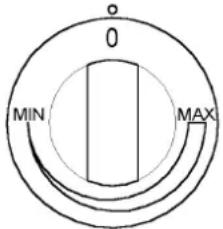
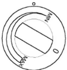
The knob's position in relation to the marker shows the current mode of operation.
OFF position:
‘0’ points to the marker (o).
ON position:
Any position between: MIN (minimum) and MAX (maximum) that points towards the marker (o).
Before doing an operational check, the user needs to know how the equipment is operated.
Your induction unit has been placed in a suitable location and is connected to the main supply. Make sure that the equipment stands secure and can't move. The power control knob is in the “0” position.
Remove all objects from the heating zone. Make sure that the heating zone is either cracked or broken. If the heating zone is cracked or broken, stop immediately, turn off the equipment and pull out the main plug.
Warning
The heating zone is heated by the hot pan. Do not touch the heating zone, which can cause injuries
Use a pan that is suitable for induction and has a minimum bottom diameter of 12 cm. To test the Function of Units with main switch, it must switch on first. Then follow the description.
- Place a pan in the centre of the heating zone and put in some water.
- With LED: Turn the power control knob to the ON position (any position between Min. and Max.). The operation indicator lamp (red LED) either flashes (power level 10%-30%) or lights up continuously (power level 30%-100%). The water is heated.
- With Digital display: turn the performance knob on (a position between Minimum and Maximum). display shows chosen performance between (1-9).
- With LED: Remove the pan from the heating zone – the operation indicator lamp must start to flash (pan detection).
- Put the pan back on the heating zone – the operation indicator lamp lights up again and the heating process starts again.
- Turn the power control knob to the 0 position – the heating process is stopped and the operation indicator lamp goes off.
- When the operation indicator lamp is on, this means that energy is transferred to the pan.
With Digital display: Remove the pan from the heating zone – the Digital Display shows symbol for (pan detection). Overview on page 16 - Put the pan back on the heating zone – the display shows chosen performance between (1-9) and the heating process starts again.
- Turn the power control knob to the 0 position – the display goes in stand by
- When the display shows a number between (1-9), this means that energy is transferred to the Cook ware.
If the operation indicator lamp stays off or flashes only very briefly, check the following:
- Is the induction unit connected with the main supply?
- Is the power control knob in the ON position?
- Are you using a pan that is suitable for induction (test with a magnet) and have a minimum bottom diameter of 12 cm?
- Is the pan in the centre of the heating zone?
To check if the material of your pan is suitable for induction, use a magnet. It must stick slightly to the bottom of the pan. If it doesn't stick there, your pan is not suitable for use with induction units. Choose a pan recommended for use with induction units.
If the induction unit still doesn't work, please refer to the “Troubleshooting” section of this manual.
6 Operating
6.1 Cooking
The unit can be used immediately. When the operation indicator lamp lights continuously or flashes, energy is transferred to the pan. By turning the power control knob, you can choose the desired power level. How much inductive power is transferred to the pan depends on the position of the potentiometer.
Position MIN > minimum performance Position MAX > maximum performance
There are certain aspects which differ from cooking with traditional cooking systems and which you must pay special attention to:
The food reacts immediately when the cooking level is changed via the power control knob. Empty pans or pots heat up very quickly. NEVER place empty pans on the ceramic hob. Before starting to cook, first put grease or liquid into the pan. Use the power control knob to select the exact power level that matches the desired cooking method.
The pan should always be placed in the centre of the heating zone, or the pan bottom will be heated unevenly. Check the pan continuously when heating oil or grease to prevent it from overheating or burning.
Attention! Place the Cookware only with whole extent on the Cooker. Ignoring this note results to damages of the Cookware and the Equipment. Consequence when ignoring: Cookware is welded together with each other. The warm Cookware burning the seal material and the material get destroyed. This result humidity and grease can penetrate in the equipment and can result in the defect of the Equipment.
Comfort
The induction equipment only transfers energy as long as a pan is located in the heating zone. This is independent of the position of the power control knob. When you remove a pan from the heating zone, the energy transfer to the pan is stopped immediately. When you put the pan back in the heating zone, the energy level you have selected before, is again transferred to the pan.
When turning the power control knob to the OFF position, the cooking process is stopped. However, the equipment still stays ready for work (standby mode). To disconnect the unit completely, you must pull the main plug or turn the Main switch off (if available).
7 Safety instructions
7.1 Description of warning symbols and indicators
General warning signals If you don't follow the safety instructions, you will place yourself in danger of injuries.
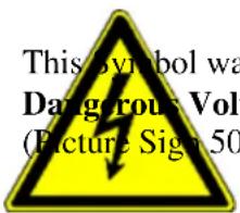
This symbol warning from
Dangerous Voltage.
(Picture Sign 5036; IEC 60417-1)
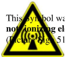
This symbol warning from
not ionizing electric magnetic radiation.
(Picture Sign 5140; IEC 60417-1)
Warning
Improper use may result in minor injuries or damages.
Warning symbols that are located directly on the equipment must always be observed. Their readability must be ensured at all times.
Warning
Before you connect or use the Induction Unit, you have to read the Operation Instructions
Warning: Read the operating instructions before using or servicing the equipment.
7.2 Dangers resulting from not observing the safety instructions
Not observing the safety instructions, may lead to danger for people, the surroundings, and the induction unit itself. We are not liable for any damages caused by a failure to observe the safety instructions.
Specifically, not observing the safety instructions could result in the following risks (among others):
- Risk of personal injuries as a result of electric factors
- Risk of personal injuries because of overheated pans
- Risk of personal injuries because of overheated ceramic hob surface
7.3 Safe Application
To ensure safe use, you must observe all of the safety instructions given in this manual, the existing national regulations for accident prevention with electrical systems as well as any company-specific work, operation, and safety instructions.
7.4 Operator Safety instructions
The surface of the ceramic hob is heated by the heat of the pan. To avoid injuries (burns), do not touch the surface of the ceramic hob.
- Attention! Place the Cookware only with whole extent on the Cooker. Ignoring this note results to damages of the Cookware and the Equipment. Consequence when ignoring: Cookware is welded together with each other. The warm Cookware burning the seal material and the material get destroyed. This result humidity and grease can penetrate in the equipment and can result in the defect of the Equipment.
In order to avoid overheating the pan, never heat an empty pan.
- Turn off the heating zone when you take away the pan for a longer period of time. This way, the heating process doesn't restart automatically as soon as a pan is put on the heating zone again. As a result, the pan will not be heated inadvertently, i.e., if someone wants to use the induction unit, they must first start the heating process by turning the knob to the 'ON' position.
- Do not put paper, carton, textiles, etc. between the pan and the ceramic hob – they could catch fire.
- Because metal objects heat up very quickly when put in contact with the turned on heating zone, never place objects other than pans on the induction unit (closed cans, aluminum foil, cutlery, jewellery, watches, etc.).
- People with a cardiac pacemaker should contact their doctor to find out whether it is safe for them to be near induction systems.
- Do not place credit cards, phone cards, cassettes, or other magnet-sensitive objects on the ceramic hob.
- The induction unit is equipped with an internal air cooling system. Avoid blocking the air inlet and outlet areas with objects (e.g. textiles). This would cause, to overheat and switch off, the unit.
- Prevent liquids from entering the equipment, and try not to let water or food flow over the pan edge. Do not jet-clean the equipment.
- If the ceramic glass is cracked or broken, the induction unit must be turned off and separated completely from the main supply. Do not touch any parts inside the induction unit.
7.5 Improper operation
The working of the induction equipment can only be guaranteed when it's used correctly. The equipment must always be operated within the limits given in the technical data.
7.6 Modification / use of spare parts
Contact the manufacturer if you intend to make any modifications to the equipment. For safety reasons, always use original parts and accessories only which have been approved by the manufacturer. If you use anything other than the original components, the manufacturer will not assume any liability for any costs that result.
7.7 Pan detection
Pans with a diameter smaller than 12 cm are not detected by the system. During operation, the operation indicator lamp is on. When using the equipment without a pan or with a pan made of a material not suitable for induction, no current is induced and the operation indicator lamp flashes only very briefly or the Display show the symbol Pan detection
7.8 Heating zone monitoring
The heating zone is monitored by a temperature sensor, beneath the ceramic glass surface. It can detect overheated pans (hot oil, empty pans); when this occurs, the energy supply is stopped. Only when the temperature has lowered to a normal value (230 °C) the system resume inducing energy to the pan.
Attention!
Only the cooking unit is protected against overheating – not the pan. The overheated pan is detected only if the ceramic surface has reached the turn-off temperature of 260 °C as a result of the heat given off by the pan.
7.9 Noises
The cooling fans are audible but switch off from time to time. Due to different operating frequencies, whistling noises may occur when several units are used in close proximity to each other or when multi-zone units with large coils are used.
To reduce the noises:
Change the power settings; use different cooking utensils; increase the distance between the coils.
8 When the unit is not in use
When the induction unit is not in use, make sure that the power control knob is not turned on inadvertently. If you do not use the induction unit for a longer period of time (several days), pull the main plug from the socket or turning off the main switch. Make sure that no liquids can get into the induction unit, and do not use excessive amounts of liquid to clean the equipment.
Warning
Do not open induction unit!
High voltage!
The induction unit may only be opened by approved, specially trained service Employee.
If the heating zone (ceramic glass surface) is cracked or broken, stop working with the equipment at once. Turn off the induction unit immediately and pull the main plug from the socket. Do not touch any parts inside the unit.
| Error Possible cause Error: correction by User- | or Service staff | |
| Pan does not heat; operation indicator lamp is OFF (dark) | No current supplied Control, is the unit connected to the power (Power cable connected?), Main switch is in Off Position, check Fuses. partly also in On-Table units like Model | |
| Power control knob | in OFF position | Main switch is in Off PositionTurn Power control knob in ON position. |
| Pan too small (pan | bottom diameter smaller than 12 cm) | Use the right Pan. |
| Pan not placed in the | centre of the heating zone (pan cannot be detected) | Put the Pan in the middle of the Heating Zone. |
| Unsuitable pan Choose for the Induction suitable Pan | *1. | |
| Induction defective | Contact your Dealer for their Repair service. Disconnect the Unit from the Power. | |
| Insufficient heating power;operation indicator lamp is ON | Pan used not ideal Choose for the Induction suitable Pan. Compare the result with your Pan. | |
| Air blocked | Take sure, the Air condulation is working (Not Blocked). | |
| Air filter clogged Clean Filter or replace Filter. | ||
| Ambient too high (cooling system cannot keep hob at its normal operating temperature)**) | Take sure; in the Air cintemptiveatome no hot Air. Reduce temperature. The Temperature may not higher be than 40°C / 110 °F. | |
| One phase missing Check the Fuses. | ||
| Induction unit defective | Contact your Dealer for the Repair service. Disconnect the Unit from the Power. | |
| The system does not react when you turn the power control knob. | Power control knob defective | Contact your Dealer for the Repair service. Disconnect the Unit from the Power. |
| The heating power switches on and off within a few minutes. The fan is working. | Air cooling system blocked | Take sure, the Air circulation is working (Not Blocked). |
| Fan dirty Clean Fan. | ||
| The heating power switches on and off within a few minutes. The fan does not work. | Fan or fan control defective | Contact your Dealer for the Repair service. Disconnect the Unit from the Power. |
| The heating power switches on and off within a few minutes (after longer, continuous operation). | Coil overheated, heating zone too hot | Turn Unit OFF, put Pan away and wait until the Heating Zone is cooled down. |
| Empty pan Turn Unit OFF, put Pan | away and wait | until the Heating Zone is cooled down. |
| Overheated oil in pan Turn Unit OFF, put Pan away and wait | until the Heating Zone is cooled down. | |
| Small metal objects (e.g. spoons, knives, etc.) are being heated on the heating zone. | Incorrect pan detection setting | Check the Logic print (only for the Service staff „Dealers“!). |
*) To check if your pan is suitable for induction, use a magnet. The magnet must stick slightly to the bottom of the pan. If it does not stick there, your pan is not suitable for use with induction units. Choose a pan material that is suitable for induction.
** The fan starts to work when the cooling plate temperature exceeds 45°C. At cooling plate temperatures over 70°C, the control printed circuit board reduces the power level automatically to keep the power printed circuit board at normal operating conditions. The induction unit will continue to work with reduced maximum performance.
9.1 Overview error messages on Display
| Short-circuit, temperature sensor, disk temperature too low (lower -15 °C) | |
| Disk temperature too high, sub-break on temperature sensor on the plate | |
| No pan on the disk (too small pan on the disk) | |
| Wrong pan on the disk's, short-circuit induction coil (μh value to low) | |
| Sub-break temperature sensor on cooling sheet (Cooler fan starts immediately) | |
| Short-circuit temperature sensor on cooling sheet (no function “booth sensors or cooling sheet”), cooler temperature too low (lower -15 °C) | |
| Sub-break of Potentiometer: Wrong value (bigger 10.5 kOhm) | |
| Electronics OK (Standby), Potentiometer on position 0 (zero) | |
| Phase missing (only 230 Volt Units) | |
| (only 400 Volt Units) L1 or L3 is missing |
List of cleaning agents for specific types of dirt and stain:
| Dirt / stain type Cleaning agent | |
| Minor stains and dirt Moist cloth (Scotch cloth) with some industrial kitchen cleaning agent | |
| Greasy Stains (sauces, soups, etc.) | PolychromeSigolin chrom,Inox crèmeVif Super CleanerSupernettoyant,Sida,Wiener KalkPudol System Care |
| Lime and water stains Polychrom | Sigolin chrom,Inox crèmeVif Super- CleanerSupernettoyant |
| Strongly shimmering, metallic discolorations | PolychromSigolin chrom |
| Mechanical cleaning Razor blade | Non-abrasive sponge |
Do not use abrasive cleaning agents, steel wool, or abrasive sponges, since these may damage the ceramic surface.
Residues of cleaning agents must be removed from the ceramic hob with a moist cloth (Scotch cloth), since they can corrode during heating. Correct maintenance of the induction hob includes regular cleaning, careful treatment, and service.
No liquids may enter the unit!
11 Maintenance
The users have to make sure, that all safety-relevant components always are in perfect working condition. The induction unit have to be inspected at least once a year by a specially trained technician from your supplier. The air filter must be checked for clogging at least every 6 months.
Warning
Do not open induction unit!
High voltage!
The induction unit must only be opened by specially trained service personnel.
12 Disposal
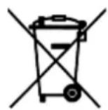
When the induction unit has reached to the end of the service life, it must be disposed of correctly.
Avoid misuse:
The equipment can't be used, by someone who is not qualified to do. Make sure, that an induction unit you want to dispose of, can't taken into operation again. The induction unit consists of common electro-mechanic and electronic parts. No batteries are used. The user is responsible for disposing of the induction unit correctly and safely.
Note for Waste management:
Units that for this point decide can be shipped to us. We take only Post-paid packets
Bartscher GmbH
natural_image
Exterior view of a modern kitchen appliance with a circular top and control buttons (no visible text or symbols)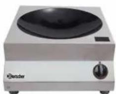
natural_image
Exterior view of a stainless steel electric stove (no visible text or symbols)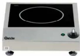
natural_image
Exterior view of a portable electrical appliance with a circular top and control knob (no visible text or symbols)
natural_image
Exterior view of a stainless steel electric stove with two circular vent holes (no text or symbols visible)
natural_image
Exterior view of a modern electric stove with two circular vent holes (no text or symbols visible)
natural_image
Exterior view of a stainless steel kitchen appliance with dual control knobs and a solar panel (no text or symbols visible)BMS, BS1C, BS1PQ, BS1P, BS2CQ, BS2PQ, BS2C, BS2PC, BS4C, BS4PC, *BS1S, BS2SK, BS2SQ, BS2SQP
BMS, BS1C, BS1P, BS1PQ, BS2CQ, BS2PQ, BS2C, BS2PC, BS4C, BS4PC, BS1S, BS2SK, BS2SQ, BS2SQP
Haute tension, danger!
natural_image
Exterior view of a stainless steel electric stove with a black dome and control knob (no visible text or symbols)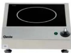
natural_image
Exterior view of a generic electronic device with a circular top and control knob (no visible text or symbols)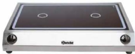
natural_image
Exterior view of a stainless steel electric stove with two circular vent holes (no text or symbols visible)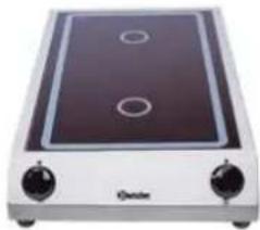
natural_image
Exterior view of a modern electric stove with two circular vented lights (no text or symbols visible)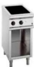
natural_image
Exterior view of a stainless steel kitchen appliance with dual control knobs and a top-mounted dish (no visible text or symbols)105.840, A105.942, A105.943, A105.946, A105.948
A105.949, A105.952, A105.953, A105.954, A105.956, A105.957, A105.935, A105.936, A105.937, A105.938, A105.939
A105.950, A105.958, A105.968, 282.410, 282.420
1 Algemeen 3
1.1 Toepassing 3
A105.942, A105.943, A105.954, 282.410, 282.420,
BI-modellen
A105.946, A105.948, A105.949, A105.952, A105.953, A105.956, A105.957
BW-modellen
105.840, A105.935, A105.936, A105.937, A105.938
Lampje "werking of panherkenning" 2V DC/ca. 10mA (rode led)
Vermogensregelaar - potentiometer 0 Ohm - 10 kOhm
Afmetingen B x D x H Keramisch vlak
| 105.840 | 330 x 380 x 175 mm | Keramische wokkom |
| A105.942,.943,.954 | 340 x 420 x 100 mm | 290 x 290 mm |
| A105.946,.948,.949 | 400 x 455 x 120 mm | 350 x 350 mm |
| A105.956,.957 | 400 x 655 x 120 mm | 350 x 560 mm |
| A105.952,.953 | 700 x 455 x 120 mm | 650 x 350 mm |
A105.935,.936,.937 400 x 455 x 180 mm Keramische wokkom
| A105.938 | 500 x 555 x 235 mm | Keramische wokkom |
| A105.950 | 400 x 400 mm | 350 x 350 mm |
| A105.958 | 400 x 700 mm | 350 x 350 mm |
| A105.968 | 700 x 700 mm | 650 x 650 mm |
| 282.410 | 400 x 700 x 860-900 mm | 350 x 605 mm |
| 282.420 | 800 x 700 x 860-900 mm | 650 x 605 mm |
Positie AAN:
natural_image
Exterior view of a modern electric stove with a black dome and control knob (no visible text or symbols)
natural_image
Exterior view of a laboratory heating appliance with a circular top and control knob (no visible text or symbols)
natural_image
Exterior view of a stainless steel electric stove with two circular vent holes (no text or symbols visible)
natural_image
Exterior view of a simple electric stove with two rotary buttons and a top circuit board (no visible text or symbols)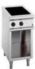
natural_image
Exterior view of a stainless steel electric stove appliance with dual doors and control knobs (no visible text or symbols)105.840, A105.942, A105.943, A105.946, A105.948
A105.949, A105.952, A105.953, A105.954, A105.956, A105.957, A105.935, A105.936, A105.937, A105.938, A105.939
A105.950, A105.958, A105.968, 282.410, 282.420
Spis treści Strona
1 Sprawy ogólne 3
1.1 Zastosowanie 3
2 Opis produktu 3
2.1 Produkty 3
A105.942, A105.943, A105.954, 282.410, 282.420,
Modele BI
A105.946, A105.948, A105.949, A105.952, A105.953, A105.956, A105.957
Modele BW
105.840, A105.935, A105.936, A105.937, A105.938
Pozycja ZAL:

- Inhaltsverzeichnis
- BI-Modelle
- BW-Modelle
- Position EIN:
- Operation instructions for Induction Units
- Contents list
- Installation
- General information
- Area of application
- Products description
- Products
- BM-Modelle
- Technical Data
- Operation and Control
- Technical Data
- Function conditions
- Electrical data of the Units
- Unit Performance (2,5 kW, 3 kW)
- Unit Performance (3,5 kW)
- Unit Performance (5 kW)
- Unit Performance (7 kW, 8 kW)
- Installation requirements
- Installation instructions
- Additional Installation instructions for the built-in Model
- For the electric Connection for the Unit take attention. The Law Regulations of the Country have to be adhered!
- Warning Wrong Voltage can damage the Induction Unit
- Warning The electrical Connection must only be implemented by specially trained staff
- Taking the Unit into Service
- Unit Assembly
- OFF position:
- ON position:
- Warning
- Operating
- Cooking
- Comfort
- Safety instructions
- Dangers resulting from not observing the safety instructions
- Safe Application
- Operator Safety instructions
- Improper operation
- Modification / use of spare parts
- Pan detection
- Heating zone monitoring
- Attention!
- Noises
- To reduce the noises:
- When the unit is not in use
- Do not open induction unit!
- High voltage!
- Overview error messages on Display
- Maintenance
- Disposal
- Note for Waste management:
- Bartscher GmbH
- BI-modellen
- BW-modellen
- Positie AAN:
- Spis treści Strona
- Modele BI
- Modele BW
- Pozycja ZAL:
Brand : BARTSCHER
Model : 105840
Category : Cooker