RK94S27F - Microwaves SHARP - Free user manual and instructions
Find the device manual for free RK94S27F SHARP in PDF.

User questions about RK94S27F SHARP
0 question about this device. Answer the ones you know or ask your own.
Ask a new question about this device
Download the instructions for your Microwaves in PDF format for free! Find your manual RK94S27F - SHARP and take your electronic device back in hand. On this page are published all the documents necessary for the use of your device. RK94S27F by SHARP.
USER MANUAL RK94S27F SHARP
INSTALLATION INSTRUCTIONS
For Sharp Carousel® Built-in Kit Models RK94S27F or RK94S30F
S = STAINLESS
THIS KIT IS UL APPROVED TO ALLOW CERTAIN MICROWAVE Ovens TO BE INSTALLED ABOVE ANY ELECTRIC WALL OVEN. PLEASE SEE THE OPERATION MANUAL REGARDING APPROVED BUILT-IN APPLICATIONS.
IMPORTANT:
This Built-in Kit is designed for and approved only for those Sharp Microwave Ovens specifying Built-In Kit RK94S27F or RK94S30F. Refer to Operation Manual for approved models.
IMPORTANT NOTES TO THE INSTALLER
- PLEASE READ THESE INSTRUCTIONS THOROUGHLY BEFORE BEGINNING INSTALLATION.
- Observe all governing codes, ordinances, and safety instructions.
- Be sure to leave these instructions with the consumer.
- Be sure to DISCONNECT THE PLUG of the microwave oven from the electrical outlet before installing the Built-in Kit. Remove the Carousel turntable from the oven cavity.
- Because the kit includes metal parts, due caution should be used in handling and installation to avoid the possibility of injury.
| ITEM | PART NAME QTY | |
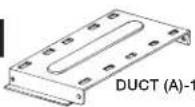
| A DUCT (A)-1: PDUC-0259WRW0 1 | ||
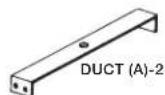
| B DUCT (A)-2: PDUC-B127MRP0 1 | ||
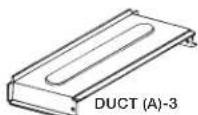
| C DUCT (A)-3: PDUC-A734WRW0 | 1 | |
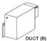
| D DUCT (B): PDUC-0260WRW0 | 1 | |
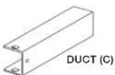
| E DUCT (C): PDUC-A274WRW0 | 1 | |
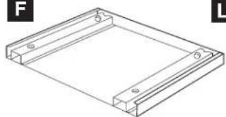
| F | BOTTOM DUCT ASSEMBLY:FDUC-B099MRK1A | 1 |
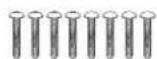
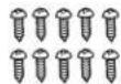
| G | M3.9-16MM PAN HEAD TAPPINGSCREW, ZINC: XOPS740P16000 | 8 |
| H WOOD SCREW: XTSS740P20000 | 2 | |
| I | CABINET SCREW: XOTS740P12000 | 10 |
| ITEM | PART NAME QTY | |
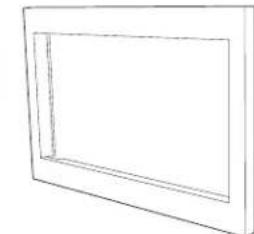
| J | FRONT FRAMERK94S27F: FDECAB229MRK0RK94S30F: FDECAB227MRK0 | 1 |
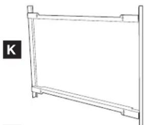
| K | BACK FRAMERK94S27F: FDECAB255MRK0RK94S30F: FDECAB226MRK0 | 1 |
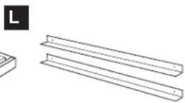
| L | AIR DEFLECTORRK94S27F: PREF-B038MRP0RK94S30F: PREF-B039MRP0 | 2 |
Check list for parts when unpacking.
NOTE: (J) FRONT FRAME and (K) BACK FRAME are shipped attached. Snap apart before installation.
A
G
B
I

C
J
D
K
natural_image
Simple line drawing of a rectangular frame with no text or symbolsE
L
natural_image
Simple line drawing of a rectangular frame with horizontal supports (no text or symbols)F
natural_image
Technical line drawing of a rectangular frame with mounting holes and side markers (no text or symbols)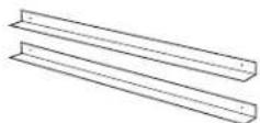
STANDARD INSTALLATION INSTRUCTIONS
STEP 1 - CABINET OR WALL OPENING
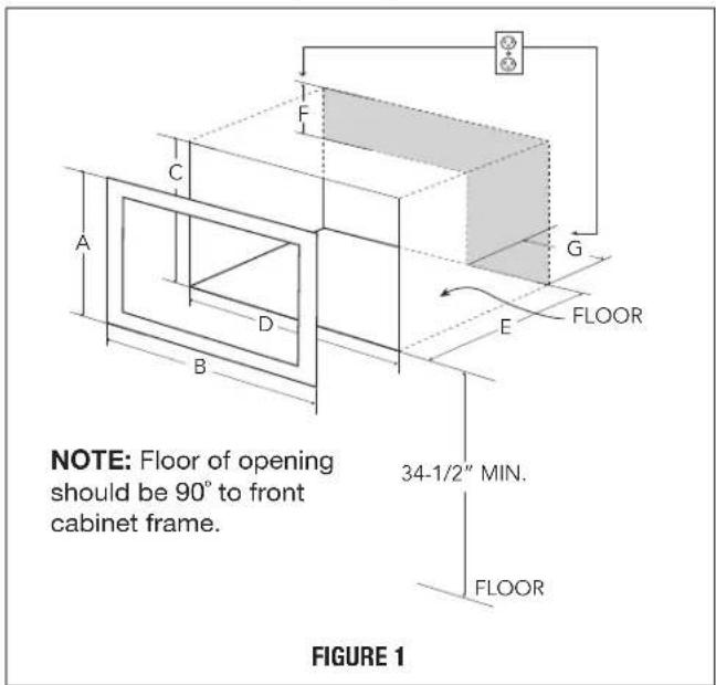
Provide an opening in the wall or cabinet as indicated in Figure 1. The depth should be a minimum of 20/8" (511.2 mm). If the Depth (E) dimension is greater than 21" (533.4 mm), the outlet location may be in any area on the rear wall. The floor of the opening should be constructed of plywood strong enough to support the weight of the oven (approximately 100 lbs/45 kg) and should be level for proper operation of the oven.
NOTE: While the proper function of the oven does not require that the opening be enclosed (with sides, ceiling and rear partition), this may be required by local code, and it is suggested that the local code be checked for any such requirement.
The opening in the wall or cabinet must be within the following dimensions, centered horizontal to the cabinet.
| RK94S27F RK94S30F | ||
| A | 20" (508 mm) 20" (508 mm) | |
| B | 26 7/8" (682.6 mm) 29 | 7/8" (758.8 mm) |
| C | 18 1/2" (470 mm) 18 | 1/2" (470 mm) |
| D | 25 1/4" (641.3 mm) 25 | 1/4" (641.3 mm) |
| E | Min. 20 1/8" (511.2 mm) | Min. 20 1/8" (511.2 mm) |
| F | 5" (127 mm) | 5" (127 mm) |
| G | 10" (254 mm) 10" (254 mm) | |
Outlet should NOT be in the shaded area as indicated on Figure 1.
NOTE:
- If the dimension of DEPTH (E) is more than 21" (533.4 mm), the outlet location may be any area on the rear wall.
text_image
NOTE: Floor of opening should be 90° to front cabinet frame. FLOOR 34-1/2" MIN. FLOOR FIGURE 1STEP 2 - EXHAUST DUCT ASSEMBLY INSTALLATION
A. Insert the edge of DUCT (B) into the hold lip of DUCT (C). Secure together by using a SCREW (I) provided in the kit. See Figure 2.
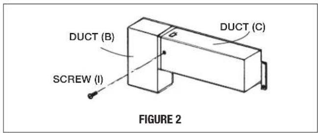
text_image
DUCT (B) DCT (C) SCREW (I) FIGURE 2B. Position DUCT (A)-1 on the top of the oven inserting edge of DUCT (BC) assembly into hole lip of DUCT (A)-1. Tighten 2 SCREWS (I), securing DUCT (A)-1 to DUCT (BC) assembly. See Figure 3.
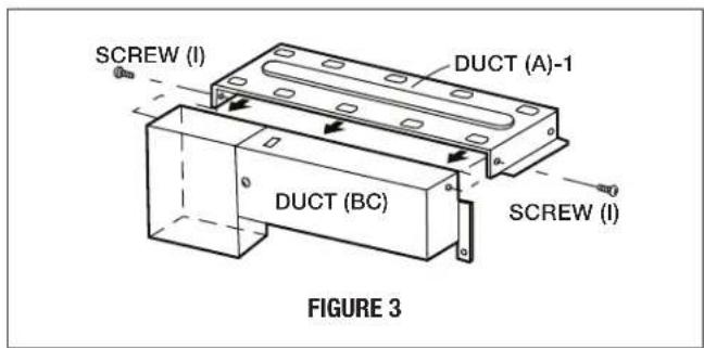
text_image
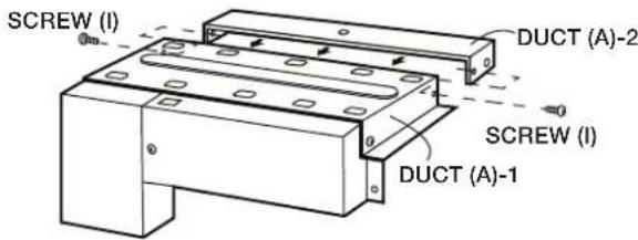
SCREW (I) DUCT (A)-1 DUCT (BC) SCREW (I) FIGURE 3C. Position DUCT (A)-2 on the top of the oven and insert it into the hold lip of DUCT (A)-1. Secure DUCT (A)-2 to DUCT (A)-1 using 2 SCREWS (I) provided. See Figure 4.
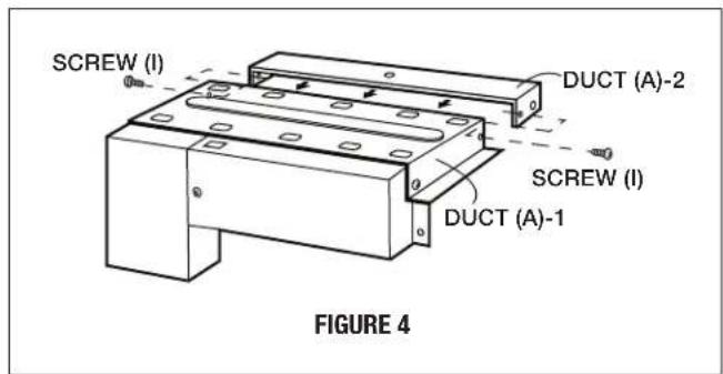
text_image
SCREW (I) DUCT (A)-2 SCREW (I) DUCT (A)-1 FIGURE 4STANDARD INSTALLATION INSTRUCTIONS
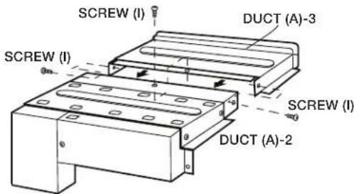
D. Position DUCT (A)-3 on top of the oven and insert it into DUCT (A)-2. Secure DUCT (A)-3 using 3 SCREWS (I) provided. See Figure 5.
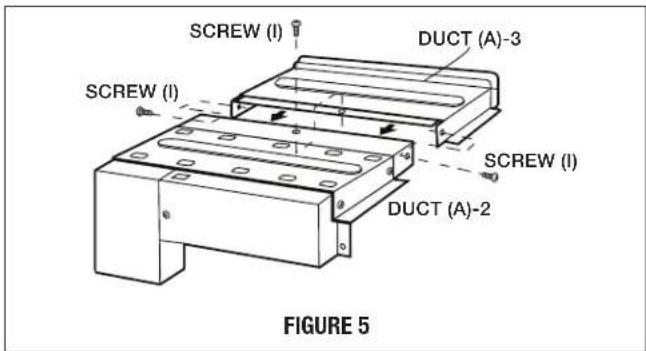
text_image
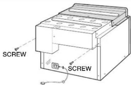
SCREW (I) DUCT (A)-3 SCREW (I) SCREW (I) DUCT (A)-2 FIGURE 5E. Remove SCREWS from the upper right and left corners at the rear of the oven. Place duct assembly on the top of the unit as shown and secure the duct assembly to the oven using the 2 SCREWS just removed from the oven. See Figure 5A.
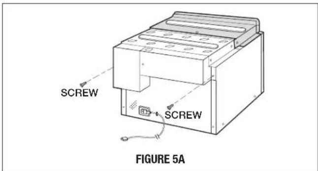
text_image
SCREW SCREW FIGURE 5ASTEP 3 - SURFACE INSTALLATION
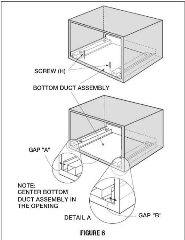
A. BOTTOM DUCT ASSEMBLY: Place the Bottom duct in the center of the opening so that gap "A" is equal to gap "B". When the BOTTOM DUCT ASSEMBLY is positioned properly, the front edge of the duct will be flush with the front of the cabinet. Secure with 2 SCREWS (H) See Figure 6.
text_image
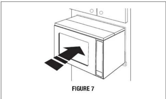
SCREW (H) BOTTOM DUCT ASSEMBLY GAP "A" NOTE: CENTER BOTTOM DUCT ASSEMBLY IN THE OPENING DETAIL A GAP "B" FIGURE 6B. CABINET INSTALLATION: Place the oven adjacent to the wall or cabinet opening. Plug the power cord into the electrical outlet. Carefully guide the assembled oven into the prepared opening. Slide the oven on the BOTTOM DUCT ASSEMBLY. See Figure 7.
natural_image
Line drawing of a microwave oven with an arrow indicating airflow or movement, labeled 'FIGURE 7' (no text on diagram itself)STANDARD INSTALLATION INSTRUCTIONS
C. CABINET INSTALLATION: Avoid pinching the cord between the oven and the wall. Adjust the position of the oven so that the feet of the oven are fitted into the holes of the BOTTOM DUCT ASSEMBLY. See Figure 8.
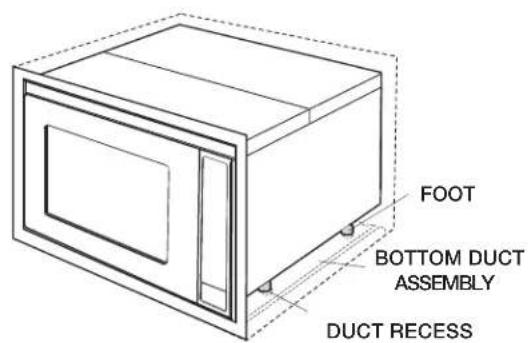
text_image
FOOT BOTTOM DUCT ASSEMBLY DUCT RECESSFIGURE 8
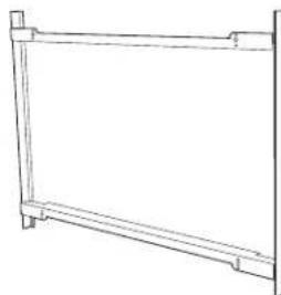
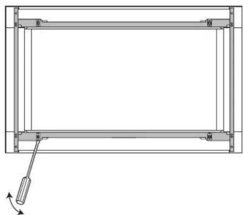
D. DISASSEMBLY: The FRONT FRAME and BACK FRAME come pre-assembled with ball studs engaged in the receivers. Separate the FRONT FRAME from the BACK FRAME. Place the assembly facedown on a protected surface. At the location of the ball stud, insert a flathead screwdriver between the FRONT FRAME and the BACK FRAME and gently pry up to disengage the ball stud from the receiver. Repeat for each corner. See Figure 9.
natural_image
Technical line drawing of a rectangular frame with supports and a hanging tool, no text or symbols presentFIGURE 9
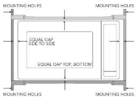
E. BACK FRAME INSTALLATION: Position BACK FRAME equal space top to bottom, side to side. Mark for 4 holes, center punch and pre-drill with 1/16" drill bit. Secure frame with 4 SCREWS (G). See Figure 10.
text_image
MOUNTING HOLES EQUAL GAP SIDE TO SIDE EQUAL GAP TOP, BOTTOM MOUNTING HOLES MOUNTING HOLES MOUNTING HOLESFIGURE 10
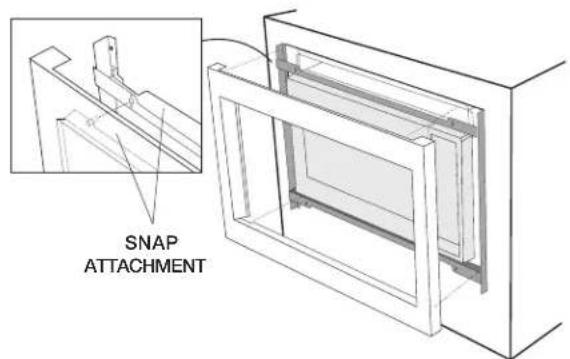
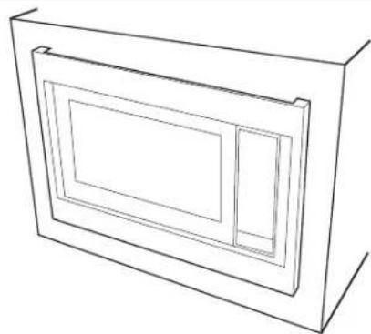
F. FRONT FRAME INSTALLATION: Place the FRONT FRAME onto the BACK FRAME and align ball studs and receivers. Secure the FRONT FRAME to the BACK FRAME by firmly pushing the FRONT FRAME onto the BACK FRAME, engaging the 4 snap attachments. See Figures 11-12.
text_image
SNAP ATTACHMENTFIGURE 11
natural_image
Line drawing of a 3D rectangular frame with internal cutouts (no text or symbols)FIGURE 12
FLUSH INSTALLATION INSTRUCTIONS
STEP 1 - CABINET OR WALL OPENING
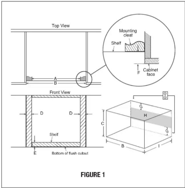
The opening in the wall or cabinet must be within the following dimensions:
| OPENING | RK94S27F RK94S30F | |
| A 25 | 1/8" (638.2 mm) 25 | 1/8" (638.2 mm) |
| Width (B) 27 | 1/8" (689 mm) 30 | 1/8" (765.2 mm) |
| Height (C) 22 | 7/16" (569.9 mm) 22 | 7/16" (569.9 mm) |
| D 1" (25.4 mm) 2 | 1/2" (63.5 mm) | |
| E | 2 1/8" (54 mm) 2 | 1/8" (54 mm) |
| F | 1 1/2" (38.8 mm) 1 | 1/2" (38.8 mm) |
| G | 5" (127 mm) | 5" (127 mm) |
| Minimum Depth (l) | 20" (508 mm) | 20" (508 mm) |
Outlet should NOT be in the shaded area H as indicated in Figure 1.
text_image
Top View Mounting cleat Shelf Cabinet face Front View D D Shelf E Bottom of flush cutout C G H G B I FIGURE 1NOTE:
Dimension C above will result in 1 1/4" (31.8 mm) spaces above and below the trim to allow for necessary intake and exhaust air flow to ensure appliance does not overheat. Do not reduce this spacing as doing so will void the warranty for any issues resulting from a lack of airflow.
NOTE:
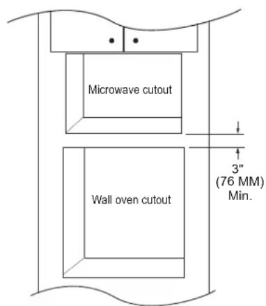
- Please allow minimum 3" (76 mm) wood gap between the microwave oven cutout and the appliance cutout below the microwave oven. See Figure 2.
text_image
Microwave cutout Wall oven cutout 3" (76 MM) Min.FIGURE 2
- The floor of the opening should be constructed of plywood strong enough to support the weight of the oven and floor load (approximately 100 pounds/45 kg). The floor should be level and 90° with the face of the cabinet for proper installation and operation of the oven. Be sure to check the local building code as it may require that the opening be enclosed with sides, ceiling and rear partition. The proper functioning of the oven does not require the enclosure.
STEP 2 - EXHAUST DUCT ASSEMBLY INSTALLATION
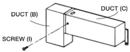
A. Insert the edge of DUCT (B) into the hold lip of DUCT (C). Secure together by using a SCREW (I) provided in the kit. See Figure 3.
text_image
DUCT (B) DUCT (C) SCREW (I)FIGURE 3
FLUSH INSTALLATION INSTRUCTIONS
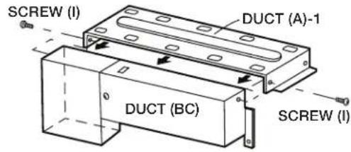
B. Position DUCT (A)-1 on the top of the oven inserting edge of DUCT (BC) assembly into hole lip of DUCT (A)-1. Tighten 2 SCREWS (I), securing DUCT (A)-1 to DUCT (BC) assembly. See Figure 4.
text_image
SCREW (I) DUCT (A)-1 DUCT (BC) SCREW (I)FIGURE 4
C. Position DUCT (A)-2 on the top of the oven and insert it into the hold lip of DUCT (A)-1. Secure DUCT (A)-2 to DUCT (A)-1 using 2 SCREWS (I) provided. See Figure 5.
text_image
SCREW (I) DUCT (A)-2 SCREW (I) DUCT (A)-1FIGURE 5
D. Position DUCT (A)-3 on top of the oven and insert it into DUCT (A)-2. Secure DUCT (A)-3 using 3 SCREWS (I) provided. See Figure 6.
text_image
SCREW (I) DUCT (A)-3 SCREW (I) SCREW (I) DUCT (A)-2FIGURE 6
E. Remove SCREWS from the upper right and left corners at the rear of the oven. Place duct assembly on the top of the unit as shown and secure the duct assembly to the oven using the 2 SCREWS just removed from the oven. See Figure 6B.
text_image
SCREW SCREWFIGURE 6B
STEP 3 - EXHAUST DUCT ASSEMBLY INSTALLATION
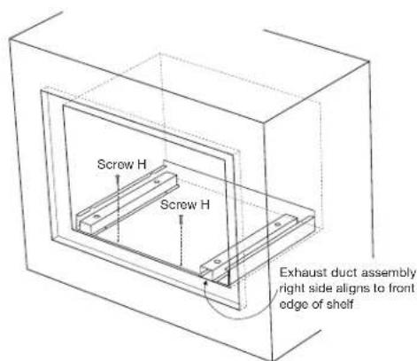
A. Place the Exhaust Duct Assembly in the center of the opening. Align the front edge of the duct with the front of the cabinet. Align the front edge of the right side of the duct with the front of the shelf. See Figure 7.
B. Secure the Exhaust Duct Assembly with 2 SCREWS (H). See Figure 7.
text_image
Screw H Screw H Exhaust duct assembly right side aligns to front edge of shelfFIGURE 7
FLUSH INSTALLATION INSTRUCTIONS
STEP 4 - FRAME INSTALLATION
A. Place the oven adjacent to the wall or cabinet opening. Plug the power cord into the electrical outlet.
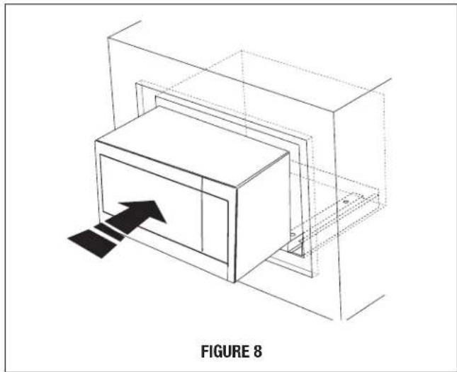
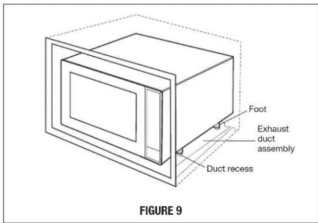
B. Carefully guide the assembled oven into the prepared opening. Slide the oven onto the Exhaust Duct Assembly. See Figure 8. Avoid pinching the cord between the oven and the wall. Adjust the position of the oven so that the feet of the oven are fitted into the recesses of the Exhaust Duct Assembly and the door opens properly. See Figure 9.
natural_image
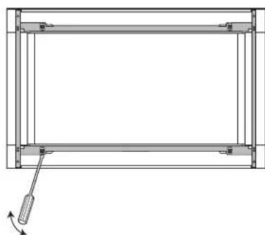
Isometric line drawing of a 3D rectangular box with an arrow pointing to it, enclosed in a transparent cube (no text or symbols)C. DISASSEMBLY: The FRONT FRAME and BACK FRAME come pre-assembled with ball studs engaged in the receivers. Separate the FRONT FRAME from the BACK FRAME. Place the assembly facedown onto a protected surface. At the location of the ball stud, insert a flathead screwdriver between the FRONT FRAME and the BACK FRAME and gently pry up to disengage the ball stud from the receiver. Repeat for each corner. See Figure 10.
natural_image
Pure technical line drawing of a rectangular frame with internal supports and a small arrow indicating direction (no text or symbols)FIGURE 10
D. BACK FRAME INSTALLATION: Position BACK FRAME equal space top to bottom, side to side. Mark for 4 holes on the installed wood cleats, center punch and pre-drill with 1/16" drill bit. Secure frame with 4 SCREWS (G). See Figure 11.
text_image
Foot Exhaust duct assembly Duct recess FIGURE 9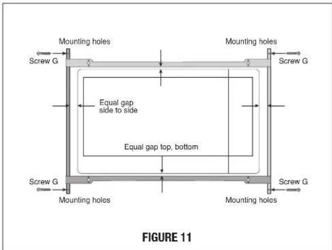
text_image
Mounting holes Mounting holes Screw G Equal gap side to side Equal gap top, bottom Screw G Mounting holes Mounting holes Screw G Figure 11E. Install Air Deflectors top and bottom. Center (left and right) the Air Deflectors above and below the installed BACK FRAME. Secure Air Deflectors with 4 SCREWS (G). See Figure 12. Mark holes and pre-drill the wood cleats with 1/16" drill bit.
natural_image
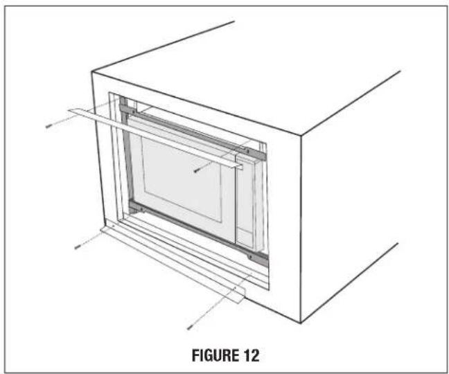
Technical line drawing of a 3D rectangular frame with internal structure, labeled as Figure 12 (no text or symbols on the diagram itself)F. FRONT FRAME INSTALLATION: Place the FRONT FRAME onto the BACK FRAME and align ball studs and receivers. Secure the FRONT FRAME to the BACK FRAME by firmly pushing the FRONT FRAME onto the BACK FRAME, engaging the 4 snap attachments. See Figures 13-14.
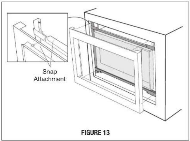
text_image
Snap Attachment FIGURE 13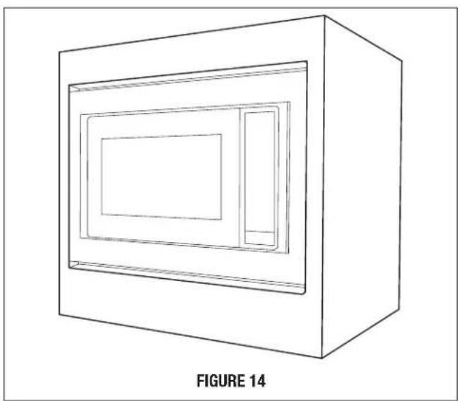
natural_image
Line drawing of a 3D rectangular box with internal compartments, labeled as Figure 14 (no text or symbols on the diagram itself)SHARP®
SHARP ELECTRONICS CORPORATION
100 Paragon Drive • Montvale, New Jersey 07645 • U.S.A.
SHARP ELECTRONICS OF CANADA LTD.
335 Britannia Road East • Mississauga, Ontario L4Z 1W9 • Canada
For any other assistance or information about this kit, in USA please call Sharp's Customer Assistance Center at
1-800-BE-SHARP (1-800-237-4277)
In Canada, call 905-568-7140
INSTRUCTIONS D'INSTALLATION
natural_image
Simple line drawing of a rectangular frame with a small black square labeled 'J' on the left (no text or symbols within the frame)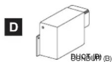
natural_image
Simple line drawing of a rectangular frame with vertical supports and a label 'K' on the left (no text or symbols on the frame itself)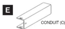
natural_image
Pure technical line drawing of three parallel metal beams with a label 'L' (no text or symbols on the beams themselves)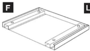
natural_image
Isometric line drawing of a rectangular frame with mounting holes, labeled F and L (no text or symbols on the diagram itself)INSTRUCTIONS D'INSTALLATION STANDARD
ÉTAPE 1 - OUVERTURE DE L'ARMOIRE OU DU MUR
text_image
CONDUIT (B) VIS (1) CONDUIT (C)SCHÉMA 2
text_image
VIS (I) CONDUIT (A)-1 CONDUIT (BC) VIS (I)SCHÉMA 3
text_image
VIS (I) CONDUIT (A)-2 VIS (I) CONDUIT (A)-1SCHÉMA 4
INSTRUCTIONS D'INSTALLATION STANDARD
text_image
VIS (I) CONDUIT (A)-3 VIS (I) VIS (I) CONDUIT (A)-2 SCHÉMA 5natural_image
Technical line drawing of a rectangular frame with a tool inserted, showing no text or symbols.SCHÉMA 9
natural_image
Line drawing of a rectangular frame with two internal compartments, no text or symbols presentSCHÉMA 12
INSTRUCTIONS D'INSTALLATION POUR L'ENCASTREMENT
ÉTAPE 1 – OUVERTURE DANS UNE ARMOIRE OU DANS LE MUR
text_image
CONDUIT (B) VIS (1) CONDUIT (C)SCHÉMA 3
INSTRUCTIONS D'INSTALLATION POUR L'ENCASTREMENT
text_image
VIS (I) CONDUIT (A)-1 CONDUIT (BC) VIS (I)SCHÉMA 4
text_image
VIS (I) CONDUIT (A)-2 VIS (I) CONDUIT (A)-1SCHÉMA 5
text_image
VIS (I) CONDUIT (A)-3 VIS (I) VIS (I) CONDUIT (A)-2SCHÉMA 6
natural_image
Isometric line drawing of a cabinet with an arrow pointing to one panel, labeled 'SCHÉMA 8' (no other text or symbols)text_image
SCHÉMA 10natural_image
Architectural diagram of a two-story building facade with internal partition and structural lines, labeled 'SCHÉMA 12' (no other text or symbols)natural_image
Line drawing of a 3D box with a recessed panel and a smaller side panel, labeled 'SCHÉMA 14' (no other text or symbols)SHARP ÉLECTRONIQUE DU CANADA LTÉE, 335, rue Britannia Est • Mississauga, Ontario L4Z 1W9 • Canada