
W10869845 - Tumble drier WHIRLPOOL - Free user manual and instructions
Find the device manual for free W10869845 WHIRLPOOL in PDF.
| Product Type | Dryer with stacking kit |
| Brand | Whirlpool |
| Model | W10869845 |
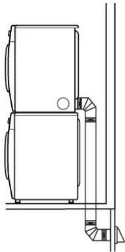
| Maximum stacked height | 1969 mm |
| Required side clearance | 152 mm |
| Required rear clearance | 127 mm |
| Required front clearance | 25 mm |
| Minimum ventilation opening (closet) | 310 cm² (top) / 155 cm² (bottom) |
| Required tools | Phillips #2 screwdriver, 2" adjustable wrench, pliers, tape measure |
| Included parts | 2 brackets, 2 plastic ties, 4 pan head screws |
| Power supply | Electric or gas (depending on dryer model) |
| Safety | Excessive weight – requires 2 persons for moving |
| Mobile home installation | Floor fixing required, additional kit no. 346764 |
| Compatibility | Front-load washers and dryers |
| Warranty | See full manual |
Frequently Asked Questions - W10869845 WHIRLPOOL
User questions about W10869845 WHIRLPOOL
0 question about this device. Answer the ones you know or ask your own.
Ask a new question about this device
Download the instructions for your Tumble drier in PDF format for free! Find your manual W10869845 - WHIRLPOOL and take your electronic device back in hand. On this page are published all the documents necessary for the use of your device. W10869845 by WHIRLPOOL.
USER MANUAL W10869845 WHIRLPOOL
natural_image
Line drawing of two stacked washing machines (no text or symbols)Kit Number W10869845
For use only with front-load washers and dryers
STACK KIT SAFETY....2
INSTALLATION REQUIREMENTS..... 2
Tools and Parts 2
Location Requirements......3
Uninstall Washer and Dryer ..... 4
If Your Washer or Dryer
Is Still in Its Packaging....4
INSTALLATION INSTRUCTIONS..... 5
Complete Installation....6
Índice
SEGURIDAD DEL JUEGO
PARA LAVADORA Y
SECADORA SUPERPUESTAS ..... 7
Your safety and the safety of others are very important.
We have provided many important safety messages in this manual and on your appliance. Always read and obey all safety messages.

This is the safety alert symbol.
This symbol alerts you to potential hazards that can kill or hurt you and others.
All safety messages will follow the safety alert symbol and either the word "DANGER" or "WARNING."
These words mean:
! DANGER
WARNING
You can be killed or seriously injured if you don't immediately follow instructions.
You can be killed or seriously injured if you don't follow instructions.
All safety messages will tell you what the potential hazard is, tell you how to reduce the chance of injury, and tell you what can happen if the instructions are not followed.
INSTALLATION REQUIREMENTS
TOOLS AND PARTS
Gather the required tools and parts before starting installation.
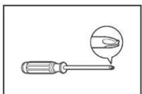
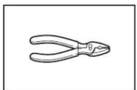
Tools needed:
natural_image
Illustration of a screwdriver with a magnified inset showing a finger pointing to a curved object (no text or symbols)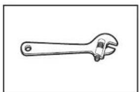
natural_image
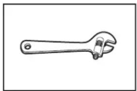
Line drawing of an adjustable wrench (no text or symbols)2 Phillips screwdriver Adjustable wrench that opens to 2" (51 mm)
natural_image
Line drawing of a pair of pliers (no text or symbols)Pliers or slip-joint pliers (for drain and inlet hoses)
natural_image
Simple diagram with three circular symbols inside a rectangular box (no text or labels)Level
natural_image
Simple line drawing of a bucket with a handle (no text or symbols)Bucket
natural_image
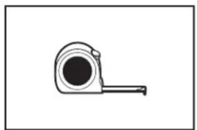
Simple line drawing of a measuring tape (no text or symbols)Tape measure
Parts supplied:
natural_image
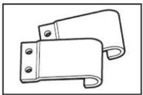
Technical line drawing of a mechanical bracket or clamp (no text or symbols)Hooked brackets (2)
natural_image
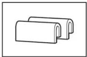
Simple line drawing of two overlapping cylindrical objects with curved ends (no text or symbols)Plastic clips (2)
natural_image
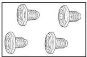
Four identical screw illustrations arranged in a 2x2 grid (no text or symbols)Feet (4)
natural_image
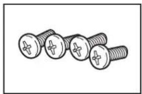
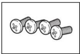
Illustration of four screws with cross marks, arranged diagonally (no text or symbols)Pan-head screws (4)
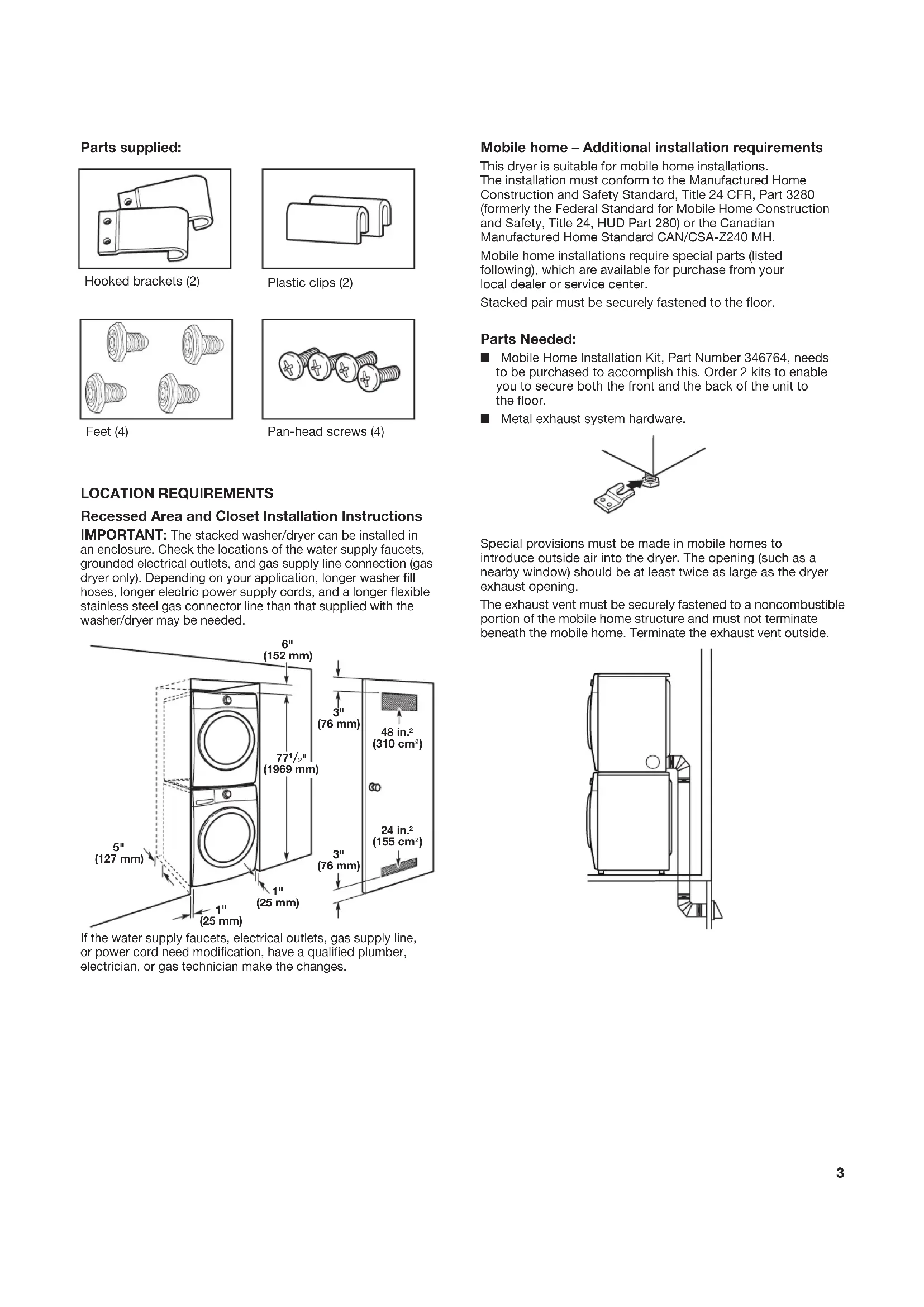
LOCATION REQUIREMENTS
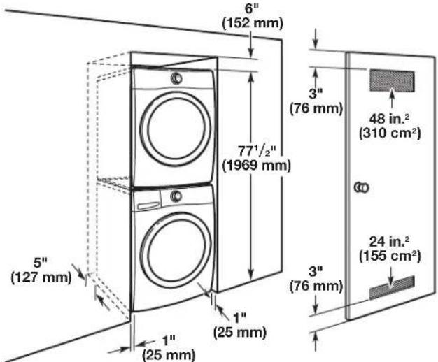
Recessed Area and Closet Installation Instructions
IMPORTANT: The stacked washer/dryer can be installed in an enclosure. Check the locations of the water supply faucets, grounded electrical outlets, and gas supply line connection (gas dryer only). Depending on your application, longer washer fill hoses, longer electric power supply cords, and a longer flexible stainless steel gas connector line than that supplied with the washer/dryer may be needed.
If the water supply faucets, electrical outlets, gas supply line, or power cord need modification, have a qualified plumber, electrician, or gas technician make the changes.
Mobile home – Additional installation requirements
This dryer is suitable for mobile home installations. The installation must conform to the Manufactured Home Construction and Safety Standard, Title 24 CFR, Part 3280 (formerly the Federal Standard for Mobile Home Construction and Safety, Title 24, HUD Part 280) or the Canadian Manufactured Home Standard CAN/CSA-Z240 MH.
Mobile home installations require special parts (listed following), which are available for purchase from your local dealer or service center.
Stacked pair must be securely fastened to the floor.
Parts Needed:
■ Mobile Home Installation Kit, Part Number 346764, needs to be purchased to accomplish this. Order 2 kits to enable you to secure both the front and the back of the unit to the floor.
■ Metal exhaust system hardware.
Special provisions must be made in mobile homes to introduce outside air into the dryer. The opening (such as a nearby window) should be at least twice as large as the dryer exhaust opening.
The exhaust vent must be securely fastened to a noncombustible portion of the mobile home structure and must not terminate beneath the mobile home. Terminate the exhaust vent outside.
natural_image
Technical line drawing of a mechanical or architectural component with no visible text or symbolsUNINSTALL WASHER AND DRYER
IMPORTANT: If your washer and dryer are already installed, they must be uninstalled.
If you need to uninstall your washer or dryer, see the Installation Instructions that came with your model for tools required.
WARNING
Excessive Weight Hazard
Use two or more people to move washer or dryer.
Failure to do so can result in back or other injury.
Uninstalling Your Washer
- Turn off the hot and cold water faucets.
- Unplug the power supply cord.
- Slowly loosen the fill hoses at the faucets to relieve the water pressure. Use a sponge or towel to absorb the released water.
- Remove the "HOT" and "COLD" fill hoses from the back of the washer. Drain water in the hoses into a bucket.
- Remove the drain hose from the wall drain pipe or utility sink and drain any water in the hose into a bucket.
Uninstalling Your Electric Dryer
- Unplug the power supply cord.
- Pull the dryer away from the wall enough to loosen the vent clamp. Loosen the clamp and gently remove the exhaust vent from the dryer exhaust outlet.
Steam Models Only: - Turn off water faucet.
- Disconnect the water inlet hose from faucet, then drain the hose into a bucket.
Uninstalling Your Gas Dryer
- Unplug the power supply cord.
- Turn off the gas supply.
- Pull the dryer away from the wall enough to loosen the vent clamp. Loosen the clamp and gently remove the exhaust vent from the dryer exhaust outlet.
- Disconnect the flexible gas supply line from the dryer. Put a piece of tape over the open ends of the gas line connection fittings.
Steam Models Only:
-
Turn off water faucet.
-
Disconnect the water inlet hose from faucet, then drain the hose into a bucket.
IF YOUR WASHER OR DRYER IS STILL IN ITS PACKAGING
WARNING
Excessive Weight Hazard
Use two or more people to move washer or dryer.
Failure to do so can result in back or other injury.
Position the packaged washer or dryer close to its final position. Cut the packaging as follows:
■ Washer: Cut plastic film along dotted cut line around the base. Remove the packaging. Do not remove the shipping bolts.
■ Dryer: Cut around top and down corners along dotted cut lines. Discard carton top, corner posts, and sides. Leave carton bottom underneath dryer.
INSTALLATION INSTRUCTIONS
WARNING
Excessive Weight Hazard
Use two or more people to move washer or dryer.
Failure to do so can result in back or other injury.
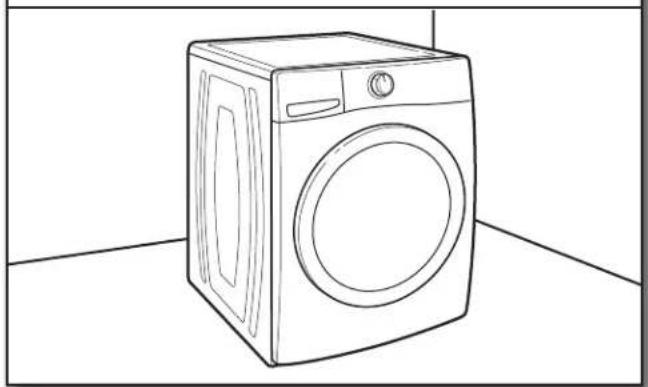
1. Move washer to its final location
natural_image
Line drawing of a washing machine on a plain floor (no text or symbols)Leave room to work behind washer. Do not remove the shipping bolts.
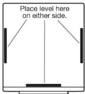
2. Check levelness of washer
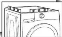
natural_image
Line drawing of a front-loading washing machine with door, vent, and rack (no text or symbols)Place a level on top edges of washer, checking each side and front. If not level, tip washer and adjust feet up or down as shown in Installation Instructions, repeating as necessary.
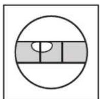
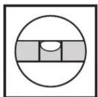
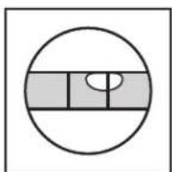
Not Level LEVEL Not Level
3. On covering, lay dryer on side or back
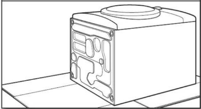
natural_image
Line drawing of a mechanical device with internal compartments and mounting holes (no text or symbols)Place a covering, such as cardboard or a blanket, on the floor to avoid damage. Gently lay the dryer down with its side or back on the covering.
4. Remove existing feet, if present
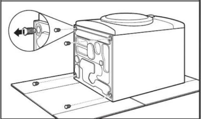
natural_image
Technical line drawing of a mechanical device with internal components and an inset showing a connector (no text or symbols)Using a wrench or slip-joint pliers, remove the existing feet if present.
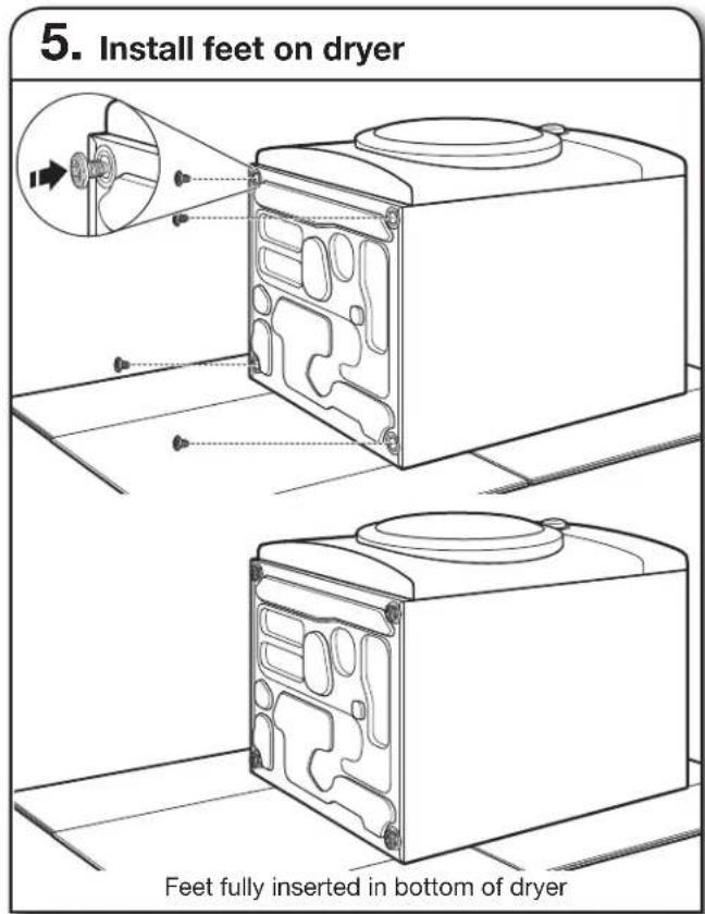
Using a wrench or slip-joint pliers, install the new feet, turning them fully into the bottom of the dryer.
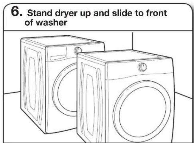
Lift the dryer back to an upright position, keeping it on the cardboard (or carton bottom). Use the cardboard to slide the dryer to the front of the washer to avoid damaging the rubber feet.
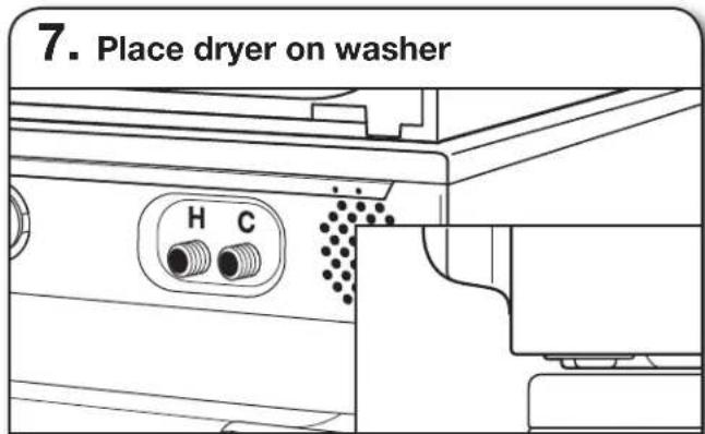
Lift the dryer up and set securely on top of washer. Position dryer to slightly overhang the back of the washer – too much overhang will allow the rear feet to slip off the back of the washer top.
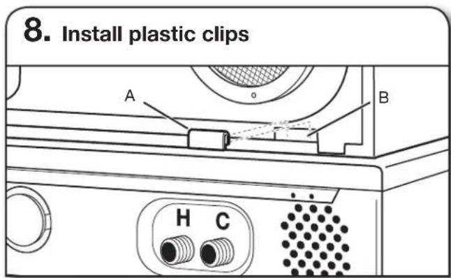
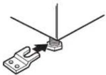
Remove the plastic clips (2), brackets (2), and pan-head screws (4) from the parts bag. Take a plastic clip (A) and, with the flat side facing out, push it down onto the lower edge of the slot (B) in the dryer back. A flat-blade screwdriver may help to open the plastic clip slightly. Repeat on other side.
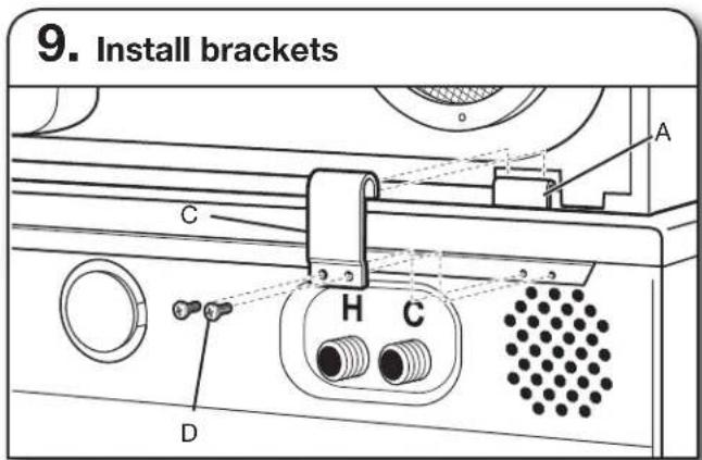
Push the hooked end of the bracket (C) down over the plastic clip (A). A flat-blade screwdriver may help to seat the bracket over the plastic clip. Slide the dryer forward as needed and attach bracket (C) to washer with pan-head screws (D). Tighten screws securely. Repeat on other side.
COMPLETE INSTALLATION
Follow the Installation Instructions that came with your washer and dryer to remove the shipping bolts and complete the installation.
natural_image
Illustration of a screwdriver with a magnified inset showing the tip detail (no text or symbols)Destornillador Phillips # 2 Llave de tuercas ajustable de 2" (51 mm)
natural_image
Line drawing of an adjustable wrench (no text or symbols)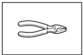
natural_image
Line drawing of a pair of pliers (no text or symbols)natural_image
Simple diagram with three circular symbols inside a rectangular box (no text or labels)Nivel

natural_image
Simple line drawing of a bucket with a handle (no text or symbols)Balde
natural_image
Simple line drawing of a measuring tape (no text or symbols)Cinta para medir
natural_image
Technical line drawing of a mechanical bracket or clamp (no text or symbols)natural_image
Simple line drawing of two overlapping cylindrical objects with rounded ends (no text or symbols)natural_image
Four identical screw illustrations arranged in a 2x2 grid (no text or symbols)Patas (4)
natural_image
Illustration of four screws with three cross-shaped fasteners (no text or symbols)natural_image
Technical line drawing of a mechanical assembly with no visible text or symbolsCÓMO DESINSTALAR LAVADORA Y LA SECADORA
natural_image
Line drawing of a front-loading washing machine (no text or symbols)natural_image
Line drawing of a front-loading washing machine with top panel and door (no text or symbols)natural_image
Line drawing of a mechanical device with internal compartments and mounting base (no text or symbols)natural_image
Technical line drawing of a mechanical device with internal components and a magnified inset showing a component detail (no text or symbols)natural_image
Technical line drawing of a mechanical device with internal components and an inset showing a close-up view of a component (no text or symbols present)natural_image
Line drawing of two washing machines on a tiled floor (no text or symbols)natural_image
Technical line drawing of a mechanical component with labeled ports H and C (no text or symbols beyond labels)natural_image
Illustration of a screwdriver with a hand gesture inside, no text or symbols presentnatural_image
Line drawing of an adjustable wrench (no text or symbols)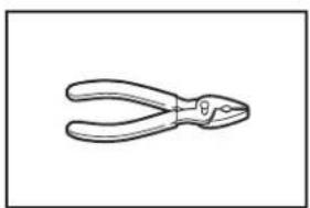
natural_image
Line drawing of a pair of pliers (no text or symbols)natural_image
Simple diagram with three circular symbols inside a rectangular box (no text or labels)Niveau
natural_image
Simple line drawing of a bucket with a handle (no text or symbols)Seau
natural_image
Simple line drawing of a measuring tape (no text or symbols)natural_image
Technical line drawing of a mechanical bracket component (no text or symbols)natural_image
Simple line drawing of two overlapping cylindrical objects with rounded ends (no text or symbols)natural_image
Four identical screw illustrations arranged in a 2x2 grid (no text or symbols)Peds (4)
natural_image
Illustration of four screws with cross marks, arranged horizontally (no text or symbols)natural_image
Technical line drawing of a mechanical assembly with no visible text or symbolsDÉSINSTALLATION DE LA LAVEUSE ET DE LA SÉCHEUSE
natural_image
Line drawing of a front-loading washing machine (no text or symbols)natural_image
Line drawing of a front-loading washing machine with control panel and door (no text or symbols)natural_image
Line drawing of a mechanical device with internal compartments and mounting base (no text or symbols)natural_image
Technical line drawing of a device casing with internal components and an inset showing a connector (no text or symbols)©/TM © 2016. All rights reserved. Used under license in Canada.
- Índice
- Your safety and the safety of others are very important.
- ! DANGER
- WARNING
- INSTALLATION REQUIREMENTS
- TOOLS AND PARTS
- Phillips screwdriver Adjustable wrench that opens to 2" (51 mm)
- LOCATION REQUIREMENTS
- Recessed Area and Closet Installation Instructions
- Mobile home – Additional installation requirements
- Parts Needed:
- UNINSTALL WASHER AND DRYER
- Uninstalling Your Washer
- Uninstalling Your Electric Dryer
- Uninstalling Your Gas Dryer
- IF YOUR WASHER OR DRYER IS STILL IN ITS PACKAGING
- INSTALLATION INSTRUCTIONS
- Move washer to its final location
- Check levelness of washer
- On covering, lay dryer on side or back
- Remove existing feet, if present
- COMPLETE INSTALLATION
- CÓMO DESINSTALAR LAVADORA Y LA SECADORA
- DÉSINSTALLATION DE LA LAVEUSE ET DE LA SÉCHEUSE
Brand : WHIRLPOOL
Model : W10869845
Category : Tumble drier