GAG31S3L - Motherboard GIGABYTE - Free user manual and instructions
Find the device manual for free GAG31S3L GIGABYTE in PDF.
User questions about GAG31S3L GIGABYTE
0 question about this device. Answer the ones you know or ask your own.
Ask a new question about this device
Download the instructions for your Motherboard in PDF format for free! Find your manual GAG31S3L - GIGABYTE and take your electronic device back in hand. On this page are published all the documents necessary for the use of your device. GAG31S3L by GIGABYTE.
USER MANUAL GAG31S3L GIGABYTE
| ☐ EN 55011 | Lunds and methods of measurement of radio destitance certificate of industrial services and materials (GN) | ☐ EN 51000-1-2 | Distances in supply systems caused by households' operations and sector sectors |
| ☐ EN 55013 | Lunds and methods of measurement of radio destitance certificate of roaders recovers and associated equipment | ☐ EN 55024 | Information Technology requirement monthly management |
| ☐ EN 55014-1 | Lunds and methods of measurement of radio destitance certificate of forested electrical appliances | ☐ EN 50082-1 | General Monthly Standard Pan T Russia, commratic and Jahr nduly |
| ☐ EN 55016 | Lunds and methods of measurement of radio destitance certificate of portable tabs and smaller electronic equipment | ☐ EN 50002-2 | General Monthly Standard Pan 2 Industrial service |
| ☐ EN 55020 | Invuity from radio manufacturers of broadband ships and internet access | ☐ EN 50091-2 | ENC requirements for unmet printing power systems (JWS) |
| ☐ EN 55022 | Lunds and methods of measurement of radio destitance certificate of information technology equipment | ☐ EN 55014-2 | Temporary requirements for household appliances and summer apparatus |
| ☐ OIN VOE 0855 | Card distribution systems Equipment for necessary and distribution from sound and television spairs | ☐ EN 50501 | CE |
| ☐ part 19 | Part 19 | ☐ EN 50501 | Supply for information technology equipment |
| ☐ CN VOE 0855 | Safety requirements for means operated electronics and related opportunities for household and smaller general use | ☐ EN 50501 | General and Safety requirements for unmet ppable power systems (JPS) |
| ☐ EN 60335 | Safety of household and similar electrical appliances | ☐ EN 50091-1 | General and Safety requirements for unmet ppable power systems (JPS) |
| ☐ EN 60065 | Safety requirements for means operated electronics and related opportunities for household and smaller general use | ☐ EN 50501 | Supply for information technology equipment |
Date: NOV. 23, 2007
Signature: Eric Lu
Representative Person's Name: ERIC LU
including that may cause undesired operation.
cause harmful and (2) this device must accept any interest received,
subject to the following two conditions: (1) This device may not
This device completes with part 15 of the FCC Rules. Operation is
Supplementary Information:
(a),Class B Digital Device
FCC Part 15, Subpart B, Section 15.107(a) and Section 15.109
Confirms to the following specifications:
Model Number: GA-G31-S3L
Product Name: Motherboard
horby declares that the product
Phone/Fax No:(818) 854-9338/ (818) 854-9339
City of Industry, CA 91748
Address: 17358 Railroad Street
Responsible Party Name: G.B.T.INC. (U.S.A.)

Per FCC Part 2 Section 2.1077(a)
DECILARATION OF CONFORMITY
版權
natural_image
Close-up of a blue printed circuit board with electronic components and a circular logo (no readable text or symbols)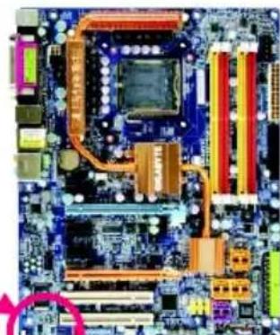
natural_image
Close-up of a computer motherboard with visible CPU socket, RAM slots, and heatsink (no text or symbols)目錄
清點配件 6
選購配件 6
GA-G31-S3L 主機板配置圖 7
晶片組功能方塊圖 8
第一章 硬體安裝 9
1-1 安裝前的注意須知 9
1-2 產品規格....10
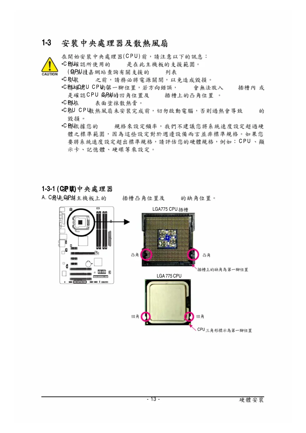
1-3 安装中央處理器及散熱風扇 13
2-5 Integrated Peripherals (整合週邊設定) 40
2-6 Power Management Setup ( 省電功能設定) 43
2-7 PnP/PCI Configurations ( 隨插即用與 PCI 組態設定) 45
2-8 PC Health Status (電腦健康狀態) 46
2-9 MB Intelligent Tweaker(M.I.T.) ( 頻率/電壓控制) 48
2-10 Load Fail-Safe Defaults (载入最安全預設值) 51
2-11 Load Optimized Defaults (载入最佳化預設值) 51
2-12 Set Supervisor/User Password (設定管理者/使用者密碼)....52
2-13 Save & Exit Setup (儲存設定值並結束設定程式) 53
2-14 Exit Without Saving (結束設定程式但不儲存設定值) 53
第三章 驅動程式安裝 55
natural_image
Top-down view of a computer motherboard showing CPU socket, RAM slots, and various ports (no readable text or symbols)natural_image
Close-up of a hand holding a black CPU socket on a blue circuit board (no visible text or symbols)步驟二:
將 CPU 插槽上的金屬上蓋翻起。
(CPJ)觸摸 插槽的接觸點。
natural_image
Close-up of hands holding a computer processor socket on a blue circuit board (no visible text or symbols)步驟三:
將 CPU 插槽保護蓋從金屬上蓋移除。
(○)保護 插槽,主機板沒有安裝
CPU 時,請將保護蓋放回金屬上蓋。
natural_image
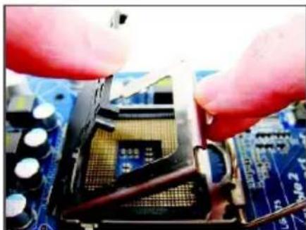
Close-up of a CPU socket with two circled regions highlighting the components (no visible text or symbols)步驟四:
以拇指及食指拿取 CPU GPU 的第
一腳位置( )CPU形標示 對齊 插槽
上的第一腳缺角處(OP)是將 上的
凹角對齊插槽上的凸角)輕輕放入。

natural_image
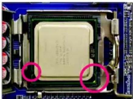
Close-up of a CPU socket on a blue circuit board (no visible text or symbols)步驟五:
natural_image
Close-up of a computer motherboard with a CPU socket and surrounding circuit components (no visible text or symbols)步驟一:
natural_image
Close-up of a computer motherboard with a black CPU fan and visible traces, no text or symbols present.步驟三:
natural_image
Close-up of a small electronic component with a metallic body and white base, placed on a blue circuit board (no visible text or symbols)步驟五:
natural_image
Close-up of a mechanical component with a highlighted circular area, placed on a blue circuit board (no visible text or symbols)步驟四:
natural_image
Close-up of a CPU socket terminal on a motherboard with visible traces and components (no readable text or symbols)步驟六:
text_image
Diagram showing computer motherboard layout with labeled memory drive units (DDRI11, DDR112, DDR113, DDR114) and a magnified view of the internal structure.可啟動雙通道記憶體的組合如下表:
natural_image
Close-up of hands installing a computer motherboard with visible CPU socket and cooling rack (no text or symbols)步驟一:
natural_image
Close-up of a computer motherboard with red and blue CPU slots, no visible text or symbols步驟二:
natural_image
Close-up of hands holding a printed circuit board with visible components and a fan (no text or symbols)- 安裝顯示卡:
natural_image
Close-up of a finger pressing a black plastic component on a computer motherboard (no visible text or symbols)- 移除顯示卡:
text_image
Diagram of electronic device rear panel with labeled ports and connectorsPS/2 键及 滑鼠插座
連接 PS/2 鍵盤及滑鼠至此插座。
text_image
Diagram of a computer motherboard with labeled components and circled annotations highlighting specific areas.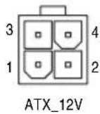
ATX_12V :
text_image
Diagram of a computer motherboard with labeled components and circled annotations indicating specific areas.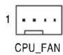
text_image
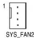
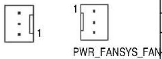
1 1 PWR_FANSYS_FANCPU_FAN :
text_image
Diagram of a computer motherboard with labeled components and a highlighted circular component.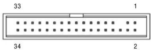
text_image
33 1 34 28) IDE1 (IDE) 插座
natural_image
Diagram of a computer motherboard layout showing CPU socket, RAM slots, and memory card (no text or labels)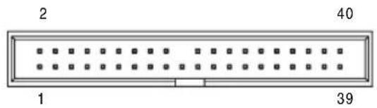
text_image
2 40 1 39text_image
Diagram of a computer motherboard layout with labeled components and connectors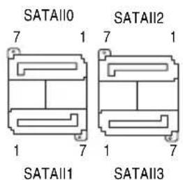
text_image
SATAII0 7 1 SATAII2 7 1 SATAII1 1 7 SATAII3 1 7natural_image
Yellow cable with black connectors, one circled in pink (no text or symbols visible)natural_image
Top-down schematic of a computer motherboard showing CPU socket, RAM slots, and various ports (no text or labels)
natural_image
Exploded view diagram of a computer motherboard showing CPU socket, RAM slots, and various hardware components (no text or labels)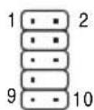
HD 接頭定義:
text_image
Diagram of a computer motherboard layout with labeled components and connectors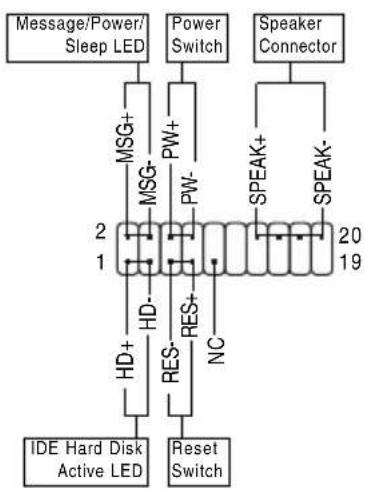
flowchart
graph TD
    A["Message/Power/Sleep LED"] --> B["MSG+"]
    B --> C["MSG-"]
    C --> D["HD-"]
    D --> E["RES-"]
    E --> F["Reset Switch"]
    G["Power Switch"] --> H["PW+"]
    H --> I["PW-"]
    I --> J["NC"]
    K["Speaker Connector"] --> L["SPEAK+"]
    L --> M["SPEAK-"]
    N["IDE Hard Disk Active LED"] --> O["2"]
    O --> P["1"]
    P --> Q["20"]
    Q --> R["19"]
natural_image
Top-down schematic of a computer motherboard showing CPU socket, RAM slots, and memory card layout (no text or labels)
natural_image
Top-down schematic of a computer motherboard showing CPU socket, RAM slots, and memory drive components (no text or labels)
natural_image
Exploded view diagram of a computer motherboard showing CPU socket, RAM slots, and memory card (no text or labels)- - 1
natural_image
Computer motherboard diagram showing CPU socket, RAM slots, and memory card layout (no text or labels)
text_image
Diagram of a computer motherboard layout with labeled components and a highlighted circular component.
| 接腳 | 定義 |
| 1 NDCDA- | |
| 2 NSINA | |
| 3 NSOUT A | |
| 4 NDTRA- | |
| 5 | 接地腳 |
| 6 NDSRA- | |
| 7 NRTSA- | |
| 8 NCTSA- | |
| 9 NRIA- | |
| 10 | 無接腳 |
natural_image
Exploded view diagram of a computer motherboard showing CPU socket, RAM slots, and memory drive (no text or labels)開路:一般運作
短路:清除 CMOS 資料

·CMOS
·CMOS
natural_image
Exploded view diagram of a computer motherboard showing CPU socket, RAM slots, and memory components (no text or labels)8 1
| 接腳 | 定義 |
| 1 | 訊號腳 |
| 2 | 接地腳 |
20) BAT (電池
text_image
Diagram of a computer motherboard layout with labeled components and connectors
natural_image
Simple line drawing of a circular object with a plus sign at center (no text or symbols)▶ F11 Save CMOS to BIOS
▶ F12 Load CMOS from BIOS
■ Integrated Peripherals (整合週邊設定)
| Date (mm:dd:yy) Fri, Aug 10 2007Time (hh:mm:ss) 22:31:24IDE Channel 0 Master [None]IDE Channel 0 Slave [None]IDE Channel 2 Master [None]IDE Channel 2 Slave [None]IDE Channel 3 Master [None]IDE Channel 3 Slave [None]Drive A [1.44M, 3.5"]Floppy 3 Mode Support [Disabled]Halt On [All, But Keyboard]Base Memory 640KExtended Memory 510MTotal Memory 512M | Item Help |
| Menu Level▶ | |
| ↑↓→←: Move Enter: Select +/-/PU/PD: Value F10: Save ESC: Exit F1: General HelpF5: Previous Values F6: Fail-Safe Defaults F7: Optimized Defaults | |
Date (mm:dd:yy) (日期設定)
▶ IDE Channel 0 Master/Slave
▶ Extended IDE Drive
▶ Precomp (Precompensation)償磁區
| CMOS Setup Utility-Copyright (C) 1984-2007 Award Software Integrated Peripherals | ||
| On-Chip Primary PCI IDE [Enabled] On-Chip SATA Mode [Auto] x PATA IDE Set to Ch.0 Master/Slave SATA Port0/2 Set to Ch.2 Master/Slave SATA Port I/3 Set to Ch.3 Master/Slave USB Controller [Enabled] USB 2.0 Controller [Enabled] USB Keyboard Support [Disabled] USB Mouse Support [Disabled] Legacy USB storage detect [Enabled] Azalia Codec [Auto] Onboard H/W LAN [Enabled] SMART LAN [Press Enter] Onboard LAN Boot ROM [Disabled] Onboard Serial Port 1 [3F8/IRQ4] Onboard Parallel Port [378/IRQ7] Parallel Port Mode [SPP] | Item Help | |
| Menu Level▶ | ||
| ↑↓→←: Move Enter: Select +/-/PU/PD: Value F10: Save ESC: Exit F1: General Help F5: Previous Values F6: Fail-Safe Defaults F7: Optimized Defaults | ||
On-Chip Primary PCI IDE (晶片組內建 IDE 控制介面)
text_image
CMOS Setup Utility-Copyright (C) 1984-2007 Award Software SMART LAN Start detecting at Port.... Pair1-2 Status = Open / Length = 0.0m Pair3-6 Status = Open / Length = 0.0m Pair4-5 Status = Open / Length = 0.0m Pair7-8 Status = Open / Length = 0.0m ↑↓→←: Move Enter: Select +/-/PU/PD: Value F10: Save ESC: Exit F1: General Help F5: Previous Values F6: Fail-Safe Defaults F7: Optimized Defaults Item Help Menu Level▶Start detecting at Port.... Link Detected --> 100Mbps Cable Length=30m
▶ Link Detected h 显示 傳輸速度
▶ Cable Length 10顯示網路線的大約線長。若線長少於,則顯示「Cable length less than 10M」。
例:Pair1-2 Status = Short / Length = 1.6m
Onboard Parallel Port (內建並列埠)
| ACPI Suspend Type [S3(STR)] Soft-Off by PWR-BTTN [Instant-Off] PME Event Wake Up [Enabled] Power On by Ring [Enabled] Resume by Alarm [Disabled] x Date (of Month) Alarm Everyday x Time (hh:mm:ss) Alarm 0:0:0 HPET Support [1st] HPET Mode [2nd] Power On By Mouse [Disabled] Power On By Keyboard [Disabled] x KB Power ON Password Enter AC Back Function [Soft-Off] | [Enabled] [32-bit mode] | Item Help |
| Menu Level▶ | ||
| ↑↓→←: Move Enter: Select +/-/PU/PD: Value F10: Save ESC: Exit F1: General Help F5: Previous Values F6: Fail-Safe Defaults F7: Optimized Defaults | ||
Soft-Off by PWR-BTTN (關機方式)
Power On by Ring (數據機開機)
Resume by Alarm (定時開機
Power On By Keyboard (鍵盤開機功能
| CMOS Setup Utility-Copyright (C) 1984-2007 Award Software PnP/PCI Configurations | ||
| PCI1 IRQ Assignment [Auto] | Item Help | |
| PCI2 IRQ Assignment [Auto] | Menu Level▶ | |
| PCI3 IRQ Assignment [Auto] | ||
| ↑↓→←: Move Enter: Select +/-/PU/PD: Value F10: Save ESC: Exit F1: General Help F5: Previous Values F6: Fail-Safe Defaults F7: Optimized Defaults | ||
3,4,5,7,9,10,11,12,14,15
由 自動指定。預設值
3,4,5,7,9,10,11,12,14,15
由 自動指定。預設值
3,4,5,7,9,10,11,12,14,15
由 自動指定。預設值
Current CPU/SYSTEM/POWER FAN Speed (RPM) (偵測風扇轉速
| Robust Graphics Booster [Auto] CPU Clock Ratio (10) [18X] CPU Frequency 2.00GHz(200x10) CPU Host Clock Control [Disabled] x CPU Host Frequency (Mhz) 200 PCI Express Frequency (Mhz) [Auto] C.I.A. 2 [Disabled] Performance Enhance [Turbo] System Memory Multiplier (SPD) [Auto] Memory Frequency (Mhz) 800 800 ***** System Voltage Optimized ***** System Voltage Control [Manual] DDR2 OverVoltage Control [Normal] PCI-E OverVoltage Control [Normal] FSB OverVoltage Control [Normal] (G)MCH OverVoltage Control [Normal] CPU Voltage Control [Normal] Normal CPU Vcore 1.38750V | Item Help |
| Menu Level▶ | |
| ↑↓→←: Move Enter: Select +/-/PU/PD: Value F10: Save ESC: Exit F1: General Help F5: Previous Values F6: Fail-Safe Defaults F7: Optimized Defaults | |

CPU Clock Ratio (CPU) 倍頻調整 (註)
Standard CMOS Features
▶ Advanced BIOS Features
▶ Integrated Peripherals
Power Management Setup
PnP/PCI C Enter Password:
PC Health Status
MB Intelligent Tweaker(M.I.T.)
ESC: Quit
↑↓→←: Select Item
F11: Save CMOS to BIOS
F8: Q-Flash F10: Save & Exit Setup F12: Load CMOS from BIOS
Change/Set/Disable Password
"Xpress Install " is now analyzing your computer...99%
text_image
GIGABYTE™ Intel® P35/P31/G31/G33/G35/Q33/Q35/X38 Chipset Utilities CD 安装片相 驱动程式 软體應用程式 驅動程式光纜 資訊 硬體資訊 與我們聯繫 安裝品片前驅動程式 我們連鎖為您的主機器安裝以下所列出的驅動程式。驅動一丁 "Xpress install" 又自動安裝所有驅動程式。 此經被啟回取要安裝的驅動程式,可取消和啟取的驅動程式將不予安裝。 Click the "Xpress install" button to install as selected drivers. Click the "Install" button to install the drivers individually. Xpress install Yahool Toolbar Size 636.1KB Version 10 Yahool Toolbar Utility INF Update Utility Size 25MB Version 8 3 1 1009 This utility installs INF files that inform the operating system how to properly configure the chipset for specific functionality such as PCI-Express or USB Interface. Intel@Graphics Media Accelerator Driver Size 42.7MB Version 6 14 10 4854 Installs drivers for the integrated graphics controller of Intel@chipsets. This is not to be used if the system has a third party graphics card. To Enable HDMI, Make sure the "Microsoft UAA bus driver for High Definition Audio" has been installed film the motherboard driver disk and your operation system has been updated with the latest Service Pack for Windows before installing the graphics card driver. Microsoft UAA Bus driver for High Definition Audio Size 29MB Version 5 10.0 5010 The Microsoft UAA Universal Audio Architecture Bus driver provides support for High Definition Audio (Acalia). This driver is designed to work with the following versions of Windows: Microsoft Windows Server 2022 Microsoft Windows XP Service Pack 1/2 (SP1/SP2) Microsoft Windows 2000 Service Pack 4 (SP4) Realtek HD Audio Driver *Xpress install" 進具「Click and Go」將來用自動安裝驅動程式。您選擇它要的驅動程式。而後接一下「Xpress install」說明,"Xpress install"將會自動執行安裝工作。
text_image
Boot from CD/DVD: Press any key to startup XpressRecovery2.....圖 8
text_image
Q-Flash Utility v2.02 Flash Type/Size............MXIC 25L8005 1M !! Copy BIOS completed - Pass!! Please press any key to continue步驟四:
text_image
Please select one file to update WARNING: Before you select the model name from the list below, please select the correct model name on your mainboard. If you select the wrong model name to update the IDOC, you computer would not boot. Model Name: OA-KONKE-011 NOTICE: uPmed 011, A WARD-000, Ver P1 OK Cancel步驟三:
text_image
Message Do you want to Update BIOS ? 确定 取消步驟三:
natural_image
Windows XP desktop wallpaper showing a green hill under a blue sky with clouds, no visible text or symbols on the screen.
natural_image
Close-up of hands assembling a red 3D connector on a blue circuit board (no visible text or symbols)步驟一:
natural_image
Close-up of a computer motherboard with a white plug inserted into the socket (no visible text or symbols)步驟二:
natural_image
Close-up of a hand pressing down on an electronic device with visible internal components (no text or symbols)S/PDIF 同軸輸出線
natural_image
Close-up of a finger pressing down on an electronic device with visible internal components (no text or symbols)S/PDIF 光纖輸出線
C. S/PDIF 音效輸出設定:
natural_image
Windows XP desktop wallpaper showing a green hill under a blue sky with clouds, no visible text or symbols on the screen.步驟二:
natural_image
Windows XP desktop wallpaper showing a green hill under a blue sky with clouds, no visible text or symbols on the screen.步驟四:
Management Methods on Control of Pollution from Electronic Information Products
(China RoHS Declaration)