
DVC920 - Browser CLARION - Free user manual and instructions
Find the device manual for free DVC920 CLARION in PDF.
| Product Type | Control module for 5.1 channel surround system |
| Brand | CLARION |
| Model | DVC920 |
| Dimensions (W x H x D) | 160 mm x 39 mm x 20.6 mm |
| Weight | 150 g |
| Supply voltage | 14.4 V DC (10.8 to 15.6 V admissible) |
| Power consumption | Less than 3 A |
| Ground | Negative |
| Main functions | Volume control, mute, source selection (digital 1/2, analog 1/2), acoustic settings (ADJUST MODE), Dolby Digital, Dolby Pro Logic II, parametric equalizer, DSF (Digital Sound Field), speaker on/off, filters (HPF/LPF), gain, delay, display contrast |
| Audio inputs | 2 optical digital inputs, 1 analog RCA input, 1 CeNET input |
| Audio outputs | 5.1 channels (front, center, surround, subwoofer) |
| Supported audio formats | Dolby Digital, DTS, linear PCM, Dolby Pro Logic II |
| Display | Screen with contrast adjustment and audio format indicators |
| Supplied accessories | Module cord, power harness, cable ties, cable holder, Velcro strips, instruction manual, warranty |
| Maintenance and cleaning | Clean with a soft, dry cloth. Do not use solvents or abrasive products. |
| Safety | Disconnect the battery before any wiring. Set the volume to minimum before turning off. Use a plastic rod for selectors. |
| Spare parts and repairability | Replaceable 3A fuse. RESET button for reset. In case of failure, consult a Clarion dealer or service center. |
| Warranty | Warranty card included. Keep with the manual. |
| General information | This module is designed for use with a Clarion 5.1 channel surround decoder. Not standalone. Specifications subject to change without notice. |
Frequently Asked Questions - DVC920 CLARION
User questions about DVC920 CLARION
0 question about this device. Answer the ones you know or ask your own.
Ask a new question about this device
Download the instructions for your Browser in PDF format for free! Find your manual DVC920 - CLARION and take your electronic device back in hand. On this page are published all the documents necessary for the use of your device. DVC920 by CLARION.
USER MANUAL DVC920 CLARION
Thank you for purchasing the Clarion product.
- Please read this owner's manual in its entirety before operating this equipment.
- After reading this manual, be sure to keep it in a handy place (e.g., glove compartment).
- Check the contents of the enclosed warranty card and keep it carefully with this manual
Contents
- CONFIRM BEFORE OPERATION 3
About the registered marks etc. 4 - SPECIFICATIONS 4
3.CONTROLS 5 - NOMENCLATURE 5
Control Unit Display 6 - OPERATIONS 7
Setting Acoustic Features (ADJUST MODE) 9
6.WIRING TECHNIQUES 14
How to Wire This Unit 14
Precautions Regarding Wiring 15
Installation Location 16
Installation Procedures 16 - System Expansion 17
Example: Center Unit + DVD Changer + Monitor 18 - IN CASE OF DIFFICULTY 71
20C920
280-7834-00
11
Basic Operations
- ST-88K Sirec sound with 86kHz sampling
Cn:2rnnnne nnnnne rannnnnne
-2:2:From 2-channel sound: surround 2-
CHINHE2000
50
-3.1: Front 3-channel course: surround men
2019年度
-Fs ERR: Current signal input has sampling
Frequency other than 32kHz, 44.1kHz
4ekliz,or 9ekliz
CLIP: DSP out of loop
Methods:
The signals are output from the ANXA GC 7 controller in a PWM signal processor. They are made up of 1000 transistors and 24-bit ADCs.
DSE setting
DISF (Digital Sound Frights) makes it possible through sound education to enjoy the acoustie experience you would have in a concert hall or a lost performance hall.
Any one of six sound offset patterns can also be applied to the sound in its signal format D1S, Digity Digital, or Linear PCM (or after decoding Digity Pro Logic II signature).
The initial setting is (DSF OFF).
Press the [DSF] button
Each time the [DSF] button is pressed, the in
dications charge as shown below.
[DSF OFF]HALL [CHURCH]
[STK]
()
-
STADIUM!StadiLmiLarge stadium without
-001C7W98.
LIVE/Live:The performance hall, larger than
a)
JAZZCLUBJAZZclubJAZZ club with a law
215150
THEATER,1108167070f01816294
butter is not enough during a 7 year
Innual
Adjusting the sound volume
lance of each speaker
UIDO MODE)
1
posifien and number of passengers
Press the [A-MODE] button.
Each time the [A-MODE] button is pressed.
the Indicators change as shown below.
SUB-W|→[CTR]→[BAL]→[FAD]
original mode
The original model is resumed when the bus
2016 and prsared 48 97 second inter
Press the [Aor [WOL] button to adjust
to value.
2018年/6月30日
1
19 volume
CTR (Center speaker):
Adjus center speaker volume
The volume is adjusted in line rate -6 to 9.
1
SAE (SAAH)
a
The second volume is collected in the course.
17.00
AD(Paeder).
4adjust the sound volume in the trol and rear
10
- 2017年
15
chirayourasheMTEy
and are set.
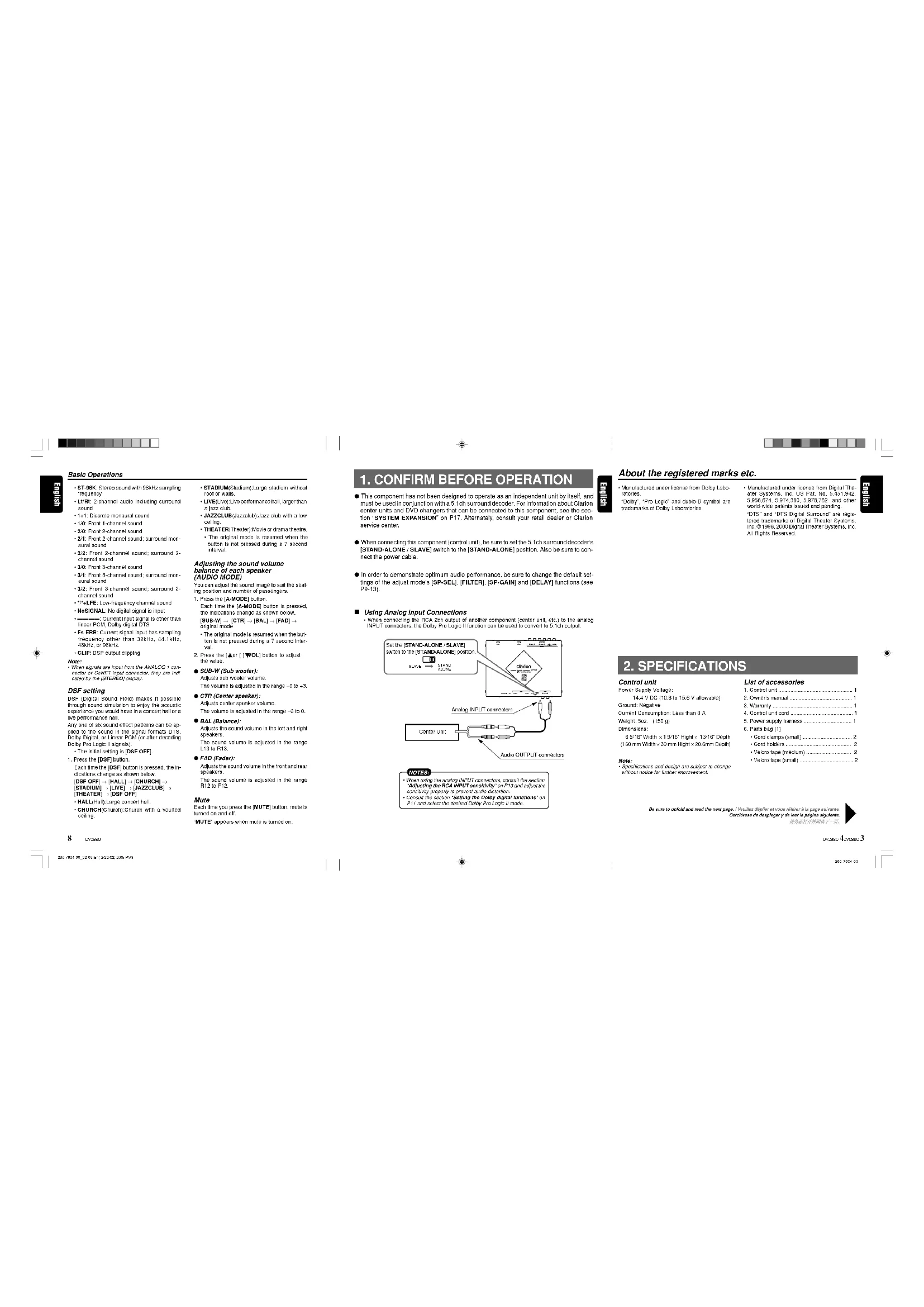
- This component has not been designed to operate as an independent unit by itself, and must be used in conjunction with a 5.1c1 surround decoder. For information about Clarion center units and DVD changes that can be connected to this component, see the "Exponential Expansion" on F17. Accordingly, consult your retail dealer or Clarion service center.
When connecting this component (contral unit), be sure to set the 5.1ch surround decoder's [STAND-ALONE: SLAVE] switch to the [STAND-ALONE] position. Also be sure to connect the power cable.
In order to demonstrate optimum audio performance, be sure to change the default settings of the adjust mode's [SP-SEL], [FILTER], [SP-GAIN] and [DELAY] functions (see P9.13).
Using Analog Input Connections
- When connecting the RCA 2ch output of another component (center unit, eta) to the analogial INPUT connectors, the Dolby Pro Logic II function can be used to convert to 0.1ch output.
E
About the registered marks etc.
Manufactured under license from Delby Laboratories, "Delby," Pro Logix and dural D symbol are trademarks at Delby Laboratories.
Manufactured under license from Digital Theraster Systems, Inc. US P3, No. 5,451,342 (US), and manufactured in the United States with other world patents issued and pending "DIS" and "DIS Digital Surround" are registered trademarks of Digital Theraster Systems, Inc., which is the leading Digital Theraster Systems, Inc. All Rights Reserved.
e
2. SPECIFICATIONS
Control unit
Power Supply Voltage:
Specifications and design are subject to change upon request for product requirements.
List of accessories
-
Contiort
-
Owner manu
-
Warnings
-
Contact us card
f.
- Power supply
C
Cordier 2
Vakrote (med) 2
·Vokratae/
200410
3.CONTROLS/LES COMMANDES/CONTROLES/控制器
Control unit IModule de commandsd Unidsd de control1主机
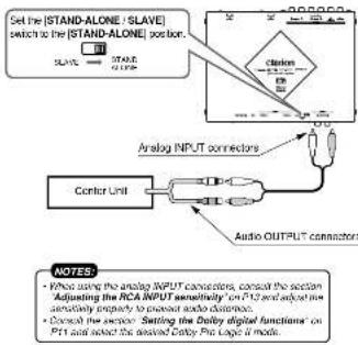
4. NOMENCLATURE
Names of Buttons
Control Unit
[VOL] bultc
Ralee and loware the volume
- Changes the adjustment value in the ADJUST MODE and AUDIO MODE
MUTELB-532
Ture off the
DISPI button
-
Changes the display
-
Changaa set Items in the ADJUST MODE
[ENT] button:
- Determines the adjustment setting in the ADJUST MODE.
SOURCE
Switches the input source.
[A-MODE] button
Adjust the volume balance in each speaker.
[ADJUST]buron:
- Invokes the ADJUST MODE to set speakers
and other
DSF) Cnner C:Chines the sound ovoctetated in the ear
POINTERSLUTH:
FONDER)OIN
n
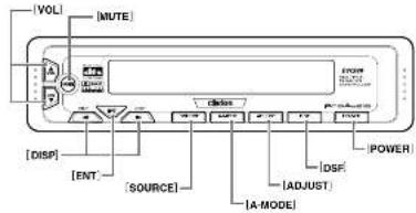
Control Unit Display
中
5. OPERATIONS
Basic Operations Note:Bo sure to read this chapter refering to the foot dropings of chapter 3. CONTROLS on page 5 (unfolds).
CAUTION Be sure to lower the volume before switching off the unit power or the ignition key. The switch-off is a great way of preventing the switch-off the power off with the volume up, when you switch the power back on, the sudden load volume may hurt your hearing and damage the unit.
Turning on/off the power
Note:
The command is used to select the 2 or 3 key within a given area. The first one is called the "start" and the second one is called "stop", you can also use it to apply the operations that are performed in the area.
1. Press the [POWER] button
2. The settings are displayed on the control unit display.
3. Press the [POWER] button to turn off the power.
Switching input source
Change the settings to suit the input signal source.
The initial setting 串 DIGITAL1
Press the [SOURCE] button.
Each line the (SOURCE) button is pressed, the initiators change as shown below. DIGITAL1 DIGITAL2 ANALOG1 ANALOG2 DIGITAL1
. The original mode is resumed when the butto be not present during a 7 second time
It is not possible using a 7.065-NTM model.
Notes:
- Sound may be introduced for a very short period.
- Wave shape forms being aspherical.
- Puts or cause abscesses are performed on the patient's head and/or lower back. The patient may have a history for a bowel infection.
DIGITAL1(Digital 1):
Use this setting when paying basic digital input. This can be used using an option-based call to digital input.
DIGITAL2(Digital 2):
Use the selling when making cash digital input. The sales data is used using an opto-fiber cable to digital input.
ANALOGY (Analog 1):
Using this setting when playing back an anteleg in your source commented using HPC4 plays.
A
Also this setting when analoging an existing Input Source connected using a CoNET cable.
Adjusting the sound volume
CAUTION
The sound volume on a DVD video disc can become very loud. For that reason, turn up the sound volume gently when the video image is displayed.
Press the [VOL] buttons on the control unit.

Increases the sound volume.
0
Note:
- Adjust the audio recording using the Excisioner or PEG.
- Adjust the recording amount to reflect the correct Dose Record.
Changing display settings
Press the [F] [DISP] button.
Each time the [or | DISP] button are
please, the indicative charge is given below [SS 1] to [SS 2] - DISIP OFF - PROGRAM OFF
SS1: displays the dolphin.

SS2: displays the airplane

DISPF:the display is off.
PROGRAM (Program):
Indicates the forma of the signals input from
the DIGITAL connectors.
MONO: Monoidal sound
STEREO: SIEE E
English
二
1 + u7 = 70%
1 + u7 = 70%
1 + u7 = 70%
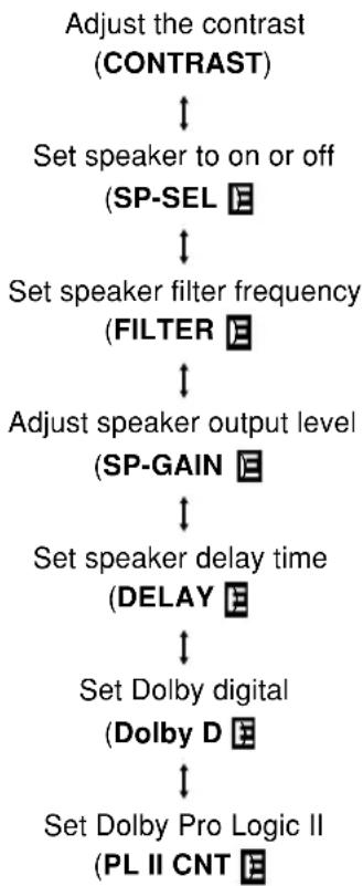
Setting Acoustic Features (ADJUST MODE)
Selecting adjust mode settings
Adjust the settings to suit your sound system.
- Press the [ADJUST] button to enter the ADJUST MODE.
- Press the [or [] DISP] button to select item to set.
Each time the [or [DISP] button is pressed, the indications change as shown below.
- This function is only available Dolby PL II's music mode selected in Dolby D function.
- When an is displayed at the end of a setting, press the [ENT] button to enter the adjust mode.
- When no F appears at the end of a menu item, the display will return to the setting contents after two seconds.
- Press the [▲or [ ]WOL] button to adjust the value.
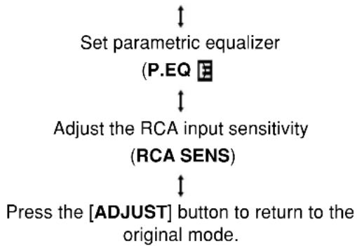
- Press the [ADJUST] button to return to the original mode.
Adjusting contrast (CONTRAST)
This function is used to adjust display contrast.
The initial value is [CNTRST.4].
- Press the [ADJUST] button to enter the ADJUST MODE.
- Press the [or [] DISP] button to show the [CONTRAST] display.
- Press the [Aor [WOL] button to adjust the contrast from [CNTRST.1] to [CNTRST.7].
- Press the [ADJUST] button to return to the original mode.
The adjustment range is [CNTRST.1] to [CNTRST.7].
Turning speakers on or off (SP-SEL)
The center speaker, rear (surround) speakers and subwoofer have to be set to on or off to achieve maximum sound quality.
The initial setting is [ON].
- Press the [ADJUST] button to enter the ADJUST MODE.
- Press the [ ]
[ISP] button to change to the [SP-SEL] display. - Press the [ENT] button to display the adjustment item.
Press the [or [] DISP] button to select [CTR-SP], [SRD-SP] or [SUB-W].
- CTR-SP: center speaker
- SRD-SP: rear (surround) speaker
-
SUB-W: subwoofer
-
Press the [▲or [ ]WOL] button to select [ON] or [OFF].
-
ON: Speaker installed
OFF: Speaker not installed - When a subwoofer is used, set [ON + ] , [ON - ] or [OFF]. The normal setting is [ON + ] , but use the [ON-] setting when this provides a better effect for low frequency range.
DVC920 9
Setting Acoustic Features (ADJUST MODE)
- Press the [ADJUST] button to return to the original mode.
Setting speaker filter frequency (FILTER)
This function is used to set a filter frequency that suits the frequency characteristics of the used speakers.
- The initial value of [F HPF], [SRD HPF] is [THROUGH] (no filter).
The initial value of [CTR HPF], [SW LPF] is [120 Hz] -
A speaker that was turned off in the Section "Turning speakers on or off" is not displayed.
-
Press the [ADJUST] button to enter the ADJUST MODE.
- Press the [ ] [ ] [DISP] button to change to the [FILTER] display.
- Press the [ENT] button to display the [F HPF].
- Press the [or [] DISP] button to select the speaker to adjust.
FHPF: high pass filter for front speakers
- CTR HPF: high pass filter for the center speaker
- SRD HPF: high pass filter for the rear (surround) speakers
- SW LPF: low pass filter for the subwoofer
-
Press the [4 or [ ]WOL] button to select the frequency.
-
In case of [F HPF] and [SRD HPF], the frequency is 50 Hz, 80 Hz, 120 Hz and [THROUGH] (no filter).
In case of [SW LPF], [CTR HPF] the frequency is 50Hz 80Hz or 120Hz -
Press the [ADJUST] button to return to the original mode.
Adjusting speaker output level (SP-GAIN)
Use the built-in test tone function of the unit to adjust the speaker output level to the same level.
The initial value is [0 dB].
- A speaker that was turned off in the Section "Turning speakers on or off" is not displayed.
- Press the [ADJUST] button to enter the ADJUST MODE.
-
Press the [ ]r [ ] [ISP] button to change to the [SP-GAIN] display.
-
Press the [ENT] button to display the adjustment item.
- In the adjustment mode, the test tone is output from the selected speaker.
- Press the [or [] [DISP] button to select the speaker to adjust.
Each time the [DISP] button is pressed, the indications change as shown below.
FRONT-L: front left speaker
CENTER: front center speaker
FRONT-R: front right speaker
SRD-R: right rear (surround) speaker
SRD-L: left rear (surround) speaker
SUB-W: rear subwoofer
- Press the [Aor [WOL] button to adjust the gain.
The adjustment range is -10dB to +10dB .
- Holding down the [Aor [] WOL] button to increase or decrease the value in a fast forwarding way.
Note:
- If the output level is raised excessively, sound may become distorted and the [CLIP] display may appear. In this event, lower the output level (GAIN) until the CLIP indicator goes off.
- Press the [ADJUST] button to return to the original mode.
Adjusting speaker delay time (DELAY)
The timing when the sound of each speaker reaches the listening position depends on speaker installation and the size of the car. Adjust the delay time of each speaker so that the sound of all speakers reach the listening position at the same time as the sound from the front speakers.
- The initial value is [0 ms].
- The delay time setting is a Dolby digital and Dolby surround function.
-
A speaker that was turned off in the Section "Turning speakers on or off" is not displayed.
-
Press the [ADJUST] button to enter the ADJUST MODE.
- Press the [ ]
[DISP] button to change to the [DELAY] display. - Press the [ENT] button to display the [CTR-SP].
Setting Acoustic Features (ADJUST MODE)
-
Press the [or [] DISP] button to select the speaker to adjust.
-
CTR-SP: center speaker
-
SRD-SP: rear (surround) speaker
-
Press the [Aor [VOL] button to adjust the delay time.
-
The [CTR-SP] adjustment range is 0 to 5 ms.
The [SRD-SP] adjustment range is 0 to 15 ms. -
Holding down the [Aor []WOL] button to increase or decrease the value in a fast forwarding way.
-
Press the [ADJUST] button to return to the original mode.
Setting the Dolby digital functions (Dolby D)
The Dolby digital functions consist of the Dolby Pro Logic II on/off function and dynamic range compression switching.
Dolby Pro Logic II:
Dolby Pro Logic II is a matrix decoding technology in which the updated digital matrix technology is applied and Dolby pro Logic is further improved. It realizes excellent 5.1 channel reproduction of Dolby surround source as well as stereo sound sources such as CDs, thereby causing a surround channel to be full-ranged (20 Hz to 20 kHz) and become stereo. Therefore, you can enjoy any stereo sources with dynamic sound of 5.1 channel.
Note:
-
The Dolby Pro Logic II function sound effects are only supported for stereo signals.
-
This function is not available when center and rear (surround) speaker were turned off in the section "Turning speakers on or off".
- Dynamic range compression function (D-RANGE):
This function compresses the dynamic range of Dolby digital to maintain low level sounds such as actor conversation and suppress loud sound volumes.
These functions are only available on Dolby digital DVD discs.
- Press the [ADJUST] button to enter the ADJUST MODE.
- Press the [ ] [ ] [ISP] button to change to the [Dolby D] display.
- Press the [ENT] button to display the [D-RANGE].
- Press the [or [] [DSP] button to select [D-RANGE] or [Dolby PL II].
-
Press the [Aor [WOL] button to select the adjustment value.
-
In [D-RANGE], settings are switched between [MAX], [STD] and [MIN].
The initial value is [MAX]. - MAX: maximum dynamic range mode of the original source
- STD: recommended mode for standard listening
MIN: the most compressed dynamic range mode that renders even low sounds easy to hear. - This button is used to turn [Dolby PL II] mode [MUSIC], [MATRIX], [MOVIE], [VIR-TUAL] and [OFF].
- The initial setting is [OFF].
- MUSIC MODE: appropriate for CDs and other stereo audio.
- MATRIX MODE: appropriate for AM/FM radio audio sources.
MOVIE MODE: appropriate for audio sources such as movies.
VIRTUAL MODE: appropriate for audio sources such as movies.
Notes:
- When Dolby Pro Logic II is selected, the sound volume decreases due to the inherent response characteristics of the Dolby Pro Logic II system. As a result, the user should lower the sound volume before switching the Dolby Pro Logic II function [OFF].
- The Dolby Pro Logic II mode cannot be selected when center speaker and rear speakers have been set to [OFF] with the "Turnig speakers on or off (SP-SEL)" function.
- Press the [ADJUST] button to return to the original mode.
DVC920 11
Setting Acoustic Features (ADJUST MODE)
Setting Dolby PL II function (PL II CNT)
This function is only available Dolby PL II's [MUSIC] mode selected in [Dolby D] function.
For instructions regarding this setting, see the section "Setting the Dolby digital functions". CTR WIDTH is not available when center speaker is turned off in the section "Turning speakers on or off".
- Press the [ADJUST] button to enter the ADJUST MODE.
- Press the [or [] DISP] button to show the [PL II CNT] display.
- Press the [ENT] button to display the adjustment item.
- Press the [ ] [ ] [ISP] button to select the item.
PANorama (ON or OFF):
Selecting PANorama mode will extend the front sound field image to the rear. If surround effect does not seem to be presented sufficiently, select the setting position [ON].
The initial setting is [OFF].
DIMENSION (0 to 6):
Selecting DIMENSION mode will shift the sound field image to the front or the rear. If the balance of the sound field image is too much pulled towards the front or rear, the balance front/rear can be corrected.
The adjusting value 3 is the center position. The range of 3 to 0 shifts the balance front/ rear to the front. The range of 3 to 6 shifts the balance front/rear to the rear.
The initial value is [3].
-CTR WIDTH (0 to 7):
Selecting CTR WIDTH mode will adjust the localization of the center channel between the center speaker and the front speaker L/R.
Distributing the center channel sound to the right and left will increase the integrated sound field image, providing you with an natural spatial feeling of sound.
Setting to the value 0 will produce the center sound with the center speaker.
Setting to the value 7 will distribute the center sound to the front speaker L/R as the existing stereo sound does.
The initial value is [3].
- Press the [Aor [WOL] button to adjust the value.
- Press the [ADJUST] button to return to the original mode.
Setting parametric equalizer (P.EQ)
The parametric equalizer function allows you to adjust the frequency characteristics to suit the car.
- The initial value provides the following settings for all speakers.
$$ F R Q = 1 \mathrm {k H z}, Q = 1, G A I N = 0 \mathrm {d B} $$
- Press the [ADJUST] button to enter the ADJUST MODE.
- Press the [ ] [ ] [DSP] button to change to the [P.EQ] display.
- Press the [ENT] button to display [EFFECT].
- Press the [or [] DISP] button to select the adjustment value.
EFFECT: turns P.EQ on or off.
SIGNAL: selects the adjustment signal.
- P-NOIS: set when pink noise is to be used
MUSIC: set to use music signals
SP-SEL: selects the speakers whose P.EQ value is to be adjusted.
- FRONT: front speaker
- CENTER: center speaker
- SRD: surround speaker
BAND: selects the frequency band (Band 1 to 3) to adjust.
FREQ: selects the frequency for bands 1 to 3.
The range of adjustments is from 20Hz to 20kHz
- Holding down the [Aor [] WOL] button to increase or decrease the value continuously.
: sets the Q curve.
- Larger numbers produce a sharper Q characteristics curve while smaller numbers produce gentler characteristics. Adjustments are made in the range Q1 to Q20.
- Holding down the [Aor [] WOL] button to increase or decrease the value continuously.
12 DVC920
Setting Acoustic Features (ADJUST MODE)
GAIN: adjusts the output level.
- Adjustments are made in the range -12 dB to +12 dB.
- Holding down the [Aor [] WOL] button to increase or decrease the value continuously.
Note:
-
If the output level is raised excessively, sound may become distorted and the [CLIP] display may appear. In this event, lower the output level (GAIN) until the CLIP indicator goes off.
-
Press the [Aor [WOL] button to select the adjustment value.
- Press the [ADJUST] button to return to the original mode.
Adjusting RCA INPUT sensitivity (RCA SENS)
This fuction is used to adjust RCA input 1 sensitivity.
The initial value is [LOW].
- Press the [ADJUST] button to enter the ADJUST MODE.
- Press the [or [DISP] button to show the [RCA SENS] display.
- Press the [▲or [ ]VOL] button to select [LOW], [MID] and [HIGH].
- Press the [ADJUST] button to return to the original mode.
Notes:
- Some distortion may be heard when the input sensitivity level is set to [HIGH], depending on the kind of components connected. In this event, lower the input sensitivity level to eliminate the distortion. Also, when a Clarion center unit (4V output) is connected, we recommend that the volume be set to 30 on the center unit, and the input sensitivity level be set to [LOW].
- Under ordinary conditions, sound volume should be adjusted on this control unit.
DVC920
4S116U3
6. WIRING TECHNIQUES
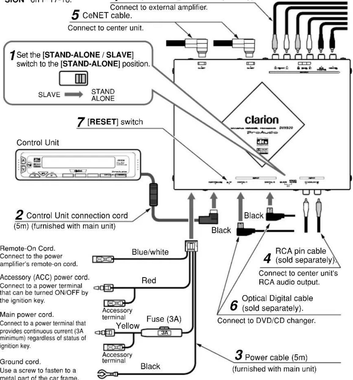
How to Wire This Unit
Perform the settings and connections in the order indicated by the drawing below.
- Steps 4-6 may differ, depending on the component connected. For detailed instructions, consult the section "SYSTEM EXPANSION" on P 17-18.
CAUTION
Throughout the process of wiring this unit, disconnect the negative (-) terminal of your automobile's battery, and leave it disconnected until completely finished. Handling wires while the terminal is connected could result in dangerous electrical shock or injury if an accidental short circuit should occur.
4 RCA pin cable (purchase separately).
14 DVC920
Precautions Regarding Wiring
1 [STAND-ALONE / SLAVE] switch
- Set the [STAND-ALONE / SLAVE] switch to the [STAND-ALONE] position.
- The factory default setting is the [SLAVE] position.
CAUTION:
When setting the position of the [STAND-ALONE / SLAVE] switch, first confirm that the 5.1ch surround decoder's CeNET cable or power connector are disconnected, then use a plastic stick to move the switch to the desired position. Also, in order to prevent damage to the switch or the possibility of short-circuit accidents, do not use metal objects, or large screwdrivers to change the switch position.
2 Control Unit cord
- Insert the control unit cord firmly until it locks securely.
- Connect the L-type plug to the decoder. The unit will not operate if the plugs are connected in reverse.
3 Power cord
- Remove the power connector label, and with the connector facing in the position shown, insert the cable connector securely into the slot until it locks.
Note:
- The power cable must be connected.
4 RCA Pin Cable (sold separately)
- When connecting an RCA pin cable, be sure to confirm the source of the connection first.
5 CeNET Cable
- To connect a CeNET cable, hold it with the connector facing as shown, and insert securely.
6 Optical Digital Cable (sold separately)
- Insert the black connector securely into the digital signal input connector until it locks. The cable clip can be used to secure up to two optical digital cables.
Note:
- Always turn the main [POWER] switch [OFF] before connecting or disconnecting digital fiber-optic cables.
7 [RESET] switch
- Following completion of wiring, press the [RESET] switch to return to default settings.
![CLARION DVC920 - [RESET] switch - 1](/content/2026/03/551274/images/e13d72fc5d4fd6d1f06d62a4e4110a426b4fa08c23d187c949d7f89836133ee7.jpg)
Be sure to set switch to [STAND-ALONE] position.
![CLARION DVC920 - [RESET] switch - 2](/content/2026/03/551274/images/b69442eb209090b3df9c7f2bdcfada007591e794fa1ad54e0c1fe2aaa6e44031.jpg)
![CLARION DVC920 - [RESET] switch - 3](/content/2026/03/551274/images/f9dc83e9564657b182cd72b6fe4505d22794b4630f5976554fb7e7e0202804a0.jpg)
![CLARION DVC920 - [RESET] switch - 4](/content/2026/03/551274/images/d79613db112aaacba42acd031f99c19dbe4c697ebe1ef6d8d207ffb5d48fca73.jpg)
DVC920 15
4S16U3
7. INSTALLATION
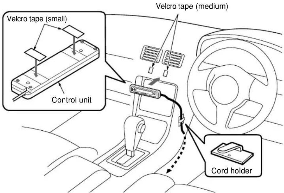
Installation Location
- The unit can be placed in your glove compartment, or fastened to the center console, etc.
NOTE:
Do not install the control unit in locations that are exposed to high temperatures (e.g., on dashboard), since deformation or damage may result.
Installation Procedures
- Apply the small Velcro tape to the control unit.
- Be sure to remove any dust or soiling from the surface of the control unit before applying the tape.
- Apply the medium Velcro tape to the center console or other location of the car you wish to install the control unit. Then press the control unit to the Velcro tape.
- Be sure to remove any dust or soiling from the car surface before applying the tape.
- Use the provided cord holder to secure the cord in place.
8. SYSTEM EXPANSION
Example: DXZ825 + DVD Changer + Monitor
Even if you have an Clarion Center Unit (CONE compliant) that cannot control 5.1ch surround sound, installing this Control Unit will make it possible to operate the component successfully.
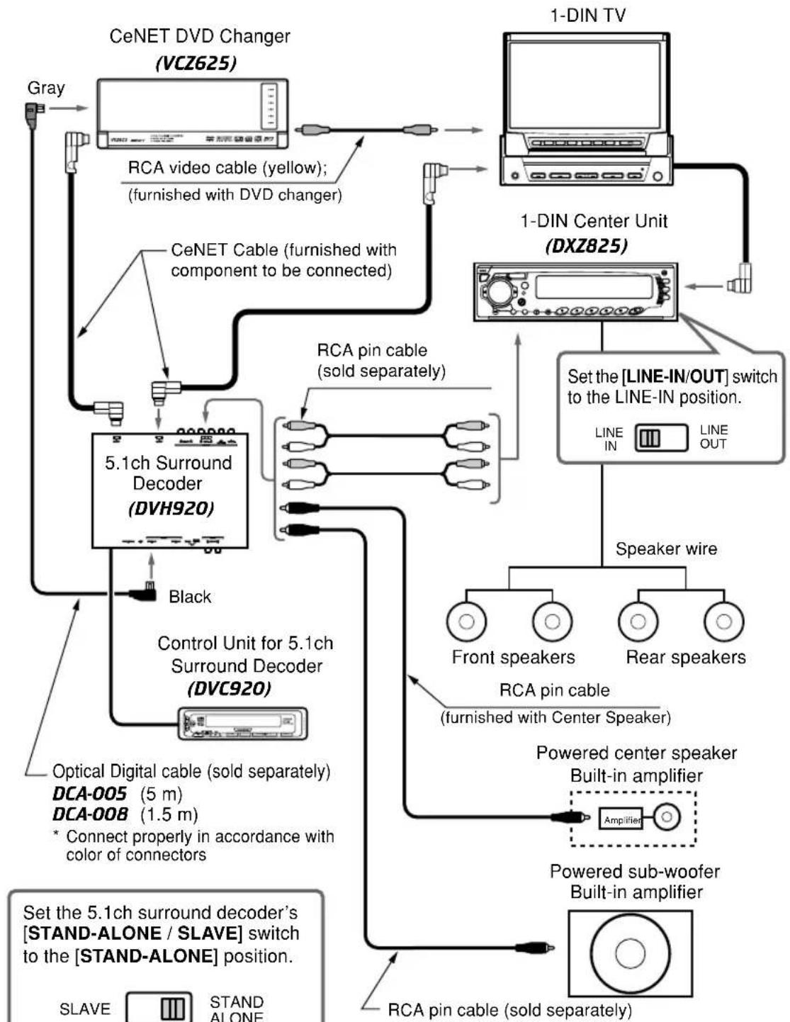
DVC920 17
Example : Center Unit + DVD Changer + Monitor
- When this control unit is connected, a 5.1ch surround decoder can be controlled, even when used with a center unit equipped with RCA 2ch audio outputs. This also makes it possible to adopt digital wiring connections for a DVD changer.
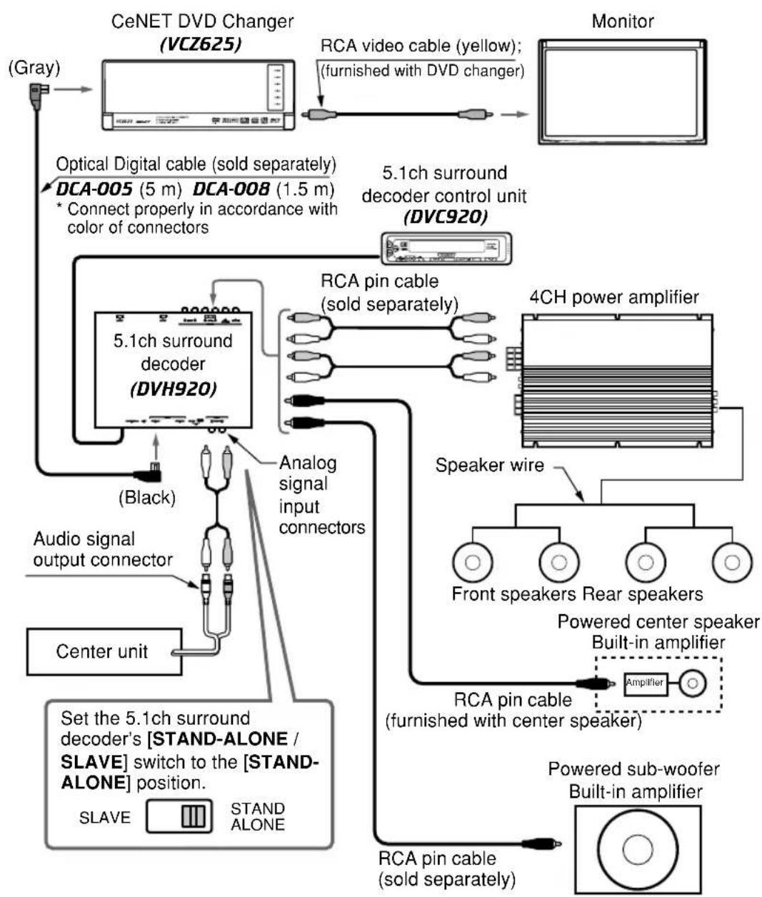
NOTES:
- Be sure to set the DVD changer's [CeNET/STAND-ALONE] switch to the [STAND-ALONE] position.
- Do not use the DVD changer's RCA audio output (AUDIO OUT) jacks.
7 Interruptor [RESET]
| Problem | Cause Measure | |
| Power does not turn on. (No sound is produced.) | Fuse is blown. | Replace with a fuse 3A of the same amperage. If the fuse blows again, consult your store of purchase. |
| Incorrect wiring. | Consult your store of purchase. | |
| Nothing happens when buttons are pressed. | The microprocessor has malfunctioned due to noise, etc. | Use a narrow stick to press the [RESET] switch on the side of the 5.1ch surround decoder. Note that when the [RESET] switch is pressed, all titles and other data placed in memory will be erased. 5.1ch surround decoder [RESET] switch decoder |
9. EN CAS DE DIFFICULTÉ

- Contents
- Basic Operations
- CLIP: DSP out of loop
- DSE setting
- Adjusting the sound volume
- lance of each speaker
- UIDO MODE)
- 15
- Using Analog Input Connections
- E
- About the registered marks etc.
- SPECIFICATIONS
- Control unit
- List of accessories
- 3.CONTROLS/LES COMMANDES/CONTROLES/控制器
- NOMENCLATURE
- Names of Buttons
- Control Unit Display
- OPERATIONS
- CAUTION
- English
- Setting Acoustic Features (ADJUST MODE)
- Selecting adjust mode settings
- Adjusting contrast (CONTRAST)
- Turning speakers on or off (SP-SEL)
- Setting speaker filter frequency (FILTER)
- Adjusting speaker output level (SP-GAIN)
- Note:
- Adjusting speaker delay time (DELAY)
- Setting the Dolby digital functions (Dolby D)
- Dolby Pro Logic II:
- - Dynamic range compression function (D-RANGE):
- Notes:
- Setting Dolby PL II function (PL II CNT)
- PANorama (ON or OFF):
- DIMENSION (0 to 6):
- -CTR WIDTH (0 to 7):
- Setting parametric equalizer (P.EQ)
- DVC920
- Adjusting RCA INPUT sensitivity (RCA SENS)
- 4S116U3
- WIRING TECHNIQUES
- How to Wire This Unit
- Precautions Regarding Wiring
- [STAND-ALONE / SLAVE] switch
- CAUTION:
- Control Unit cord
- Power cord
- RCA Pin Cable (sold separately)
- CeNET Cable
- Optical Digital Cable (sold separately)
- [RESET] switch
- 4S16U3
- INSTALLATION
- Installation Location
- Installation Procedures
- SYSTEM EXPANSION
- Example: DXZ825 + DVD Changer + Monitor
- Example : Center Unit + DVD Changer + Monitor
- Interruptor [RESET]
- EN CAS DE DIFFICULTÉ
Brand : CLARION
Model : DVC920
Category : Browser