
MKC2157AS - Microwave Oven MAYTAG - Free user manual and instructions
Find the device manual for free MKC2157AS MAYTAG in PDF.
| Product Type | Built-in Microwave Oven |
| Brand | Maytag |
| Model | MKC2157AS |
| Installation Dimensions (Height) | 43.2 cm to 43.5 cm |
| Installation Dimensions (Width) | Adjustable ±2 mm |
| Installation Dimensions (Depth) | 50.8 cm (flush outlet) or 55.9 cm (non-flush outlet) |
| Power Supply | 120 V, 60 Hz, AC only, 15 A or 20 A, dedicated circuit recommended |
| Main Functions | Cooking, defrosting, reheating |
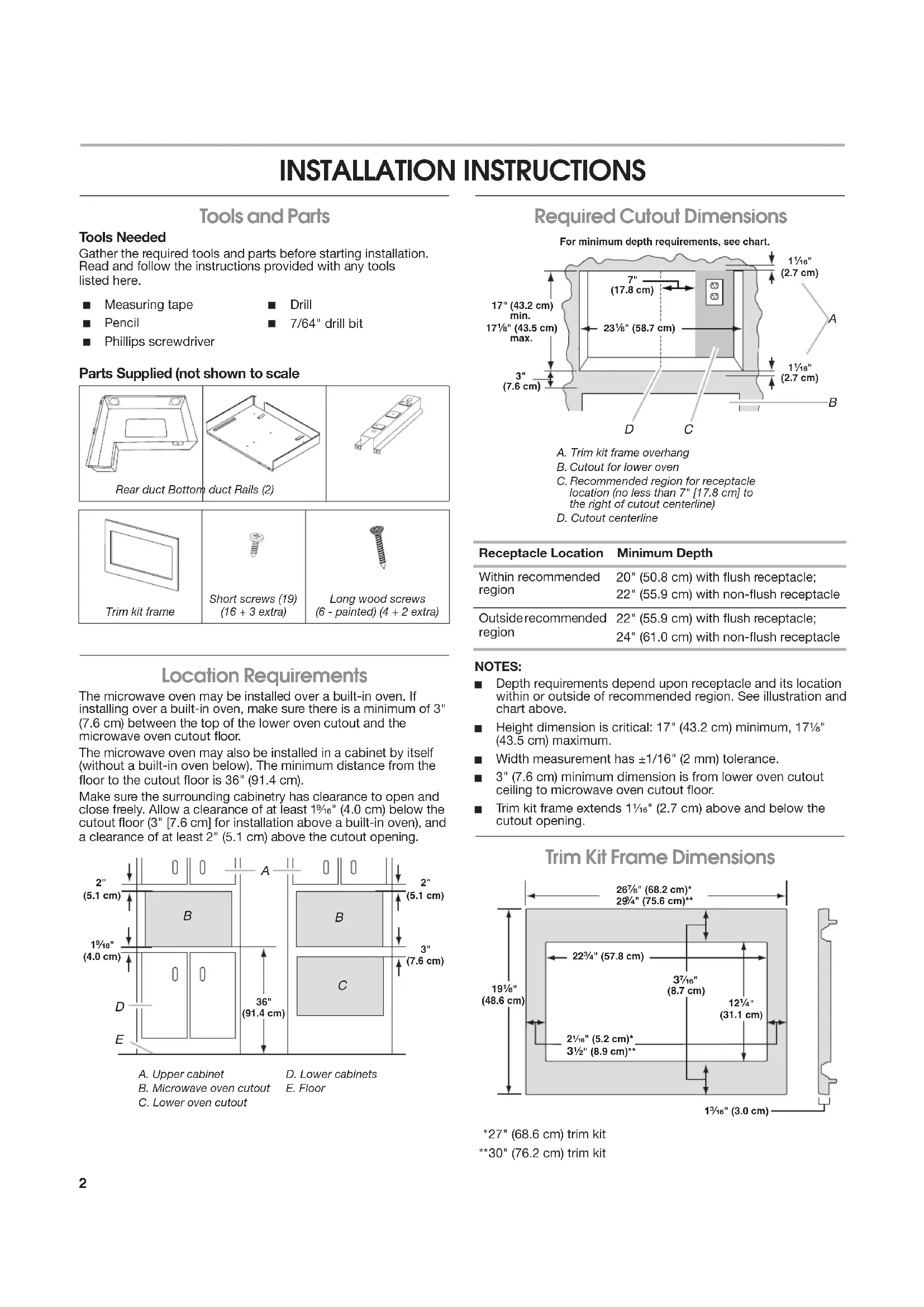
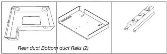
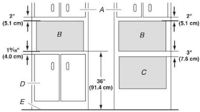
| Included Parts | Trim kit frame, short screws (19), long wood screws (6), slides, rear duct, bottom duct |
| Safety | Grounding required, do not use an extension cord, do not remove ground prong |
| Installation | Above a built-in oven or alone in a cabinet, with minimum clearances |
| Certifications | UL Listed |
Frequently Asked Questions - MKC2157AS MAYTAG
User questions about MKC2157AS MAYTAG
0 question about this device. Answer the ones you know or ask your own.
Ask a new question about this device
Download the instructions for your Microwave Oven in PDF format for free! Find your manual MKC2157AS - MAYTAG and take your electronic device back in hand. On this page are published all the documents necessary for the use of your device. MKC2157AS by MAYTAG.
USER MANUAL MKC2157AS MAYTAG
MICROWAVE OVEN BUILT-IN TRIM KIT INSTALLATION INSTRUCTIONS
Built-In Trim Kit Models MKC2157, MKC2150
UL listed for use over any electric or gas built-in oven, up to 30" (76.2 cm) wide
INSTRUCTIONS D'INSTALLATION GARNITURE ENCASTRÉE POUR FOUR À MICRO-ONDES
Tools and Parts....2
Location Requirements....2
Required Cutout Dimensions....2
Trim Kit Frame Dimensions 2
Electrical Requirements....3
Prepare Microwave Oven 3
Prepare Cutout/Cabinet Opening....4
Install the Microwave Oven....5
Install Trim Kit Frame 6
SÉCURITÉ DU FOUR À MICRO-ONDES....7
INSTRUCTIONS D'INSTALLATION .... 7
Your safety and the safety of others are very important.
We have provided many important safety messages in this manual and on your appliance. Always read and obey all safety messages.

This is the safety alert symbol.
This symbol alerts you to potential hazards that can kill or hurt you and others.
All safety messages will follow the safety alert symbol and either the word "DANGER" or "WARNING."
These words mean:
DANGER
You can be killed or seriously injured if you don't immediately follow instructions.
WARNING
You can be killed or seriously injured if you don't follow instructions.
All safety messages will tell you what the potential hazard is, tell you how to reduce the chance of injury, and tell you what can happen if the instructions are not followed.
INSTALLATION INSTRUCTIONS
Tools and Parts
Tools Needed
Gather the required tools and parts before starting installation. Read and follow the instructions provided with any tools listed here.
■ Measuring tape
Drill
Pencil
7/64" drill bit
Phillips screwdriver
Parts Supplied (not shown to scale
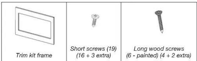
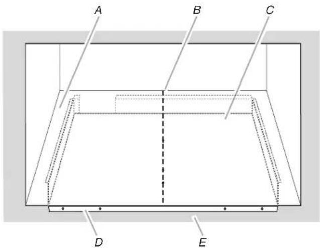
Location Requirements
The microwave oven may be installed over a built-in oven. If installing over a built-in oven, make sure there is a minimum of 3" (7.6 cm) between the top of the lower oven cutout and the microwave oven cutout floor.
The microwave oven may also be installed in a cabinet by itself (without a built-in oven below). The minimum distance from the floor to the cutout floor is 36" (91.4 cm).
Make sure the surrounding cabinetry has clearance to open and close freely. Allow a clearance of at least 1 ^9/16 " (4.0 cm) below the cutout floor (3" [7.6 cm] for installation above a built-in oven), and a clearance of at least 2" (5.1 cm) above the cutout opening.
A. Upper cabinet
B. Microwave oven cutout
C. Lower oven cutout
D. Lower cabinets
E. Floor
Required Cutout Dimensions
For minimum depth requirements, see chart.
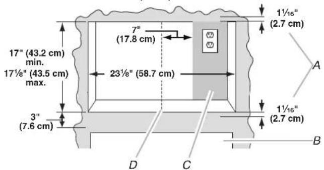
A. Trim kit frame overhang
B. Cutout for lower oven
C. Recommended region for receptacle location (no less than 7" [17.8 cm] to the right of cutout centerline)
D. Cutout centerline
| Receptacle Location | Minimum Depth |
| Within recommended region | 20" (50.8 cm) with flush receptacle; 22" (55.9 cm) with non-flush receptacle |
| Outside recommended region | 22" (55.9 cm) with flush receptacle; 24" (61.0 cm) with non-flush receptacle |
NOTES:
■ Depth requirements depend upon receptacle and its location within or outside of recommended region. See illustration and chart above.
■ Height dimension is critical: 17" (43.2 cm) minimum, 17 ^1/8 " (43.5 cm) maximum.
■ Width measurement has ±1/16" (2 mm) tolerance.
■ 3" (7.6 cm) minimum dimension is from lower oven cutout ceiling to microwave oven cutout floor.
- Trim kit frame extends 1 116 (2.7 cm) above and below the cutout opening.
Trim Kit Frame Dimensions
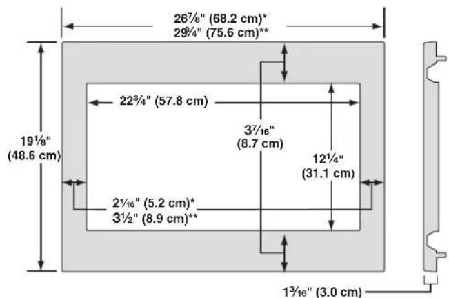
*27" (68.6 cm) trim kit
**30" (76.2 cm) trim kit
Electrical Requirements
WARNING

Electrical Shock Hazard
Plug into a grounded 3 prong outlet.
Do not remove ground prong.
Do not use an adapter.
Do not use an extension cord.
Failure to follow these instructions can result in death, fire, or electrical shock.
Observe all governing codes and ordinances.
Required:
■ A 120 V, 60 Hz, AC only, 15 A or 20 A electrical supply with a fuse or circuit breaker.
Recommended:
■ A time-delay fuse or time-delay circuit breaker.
■ A separate circuit serving only this microwave oven.
GROUNDING INSTRUCTIONS
■ For all cord connected appliances:
The microwave oven must be grounded. In the event of an electrical short circuit, grounding reduces the risk of electric shock by providing an escape wire for the electric current. The microwave oven is equipped with a cord having a grounding wire with a grounding plug. The plug must be plugged into an outlet that is properly installed and grounded.
WARNING: Improper use of the grounding plug can result in a risk of electric shock. Consult a qualified electrician or serviceman if the grounding instructions are not completely understood, or if doubt exists as to whether the microwave oven is properly grounded.
Do not use an extension cord. If the power supply cord is too short, have a qualified electrician or serviceman install an outlet near the microwave oven.
SAVE THESE INSTRUCTIONS
Prepare Microwave Oven
Attach Rails
- Unplug microwave oven before proceeding with installation.
- Remove any loose items inside microwave oven.
- Gently turn microwave oven onto its top, with the door facing forward (toward installer).
- Align the two rails on the microwave oven bottom, as shown, making sure the flanges are forward and pointing up.
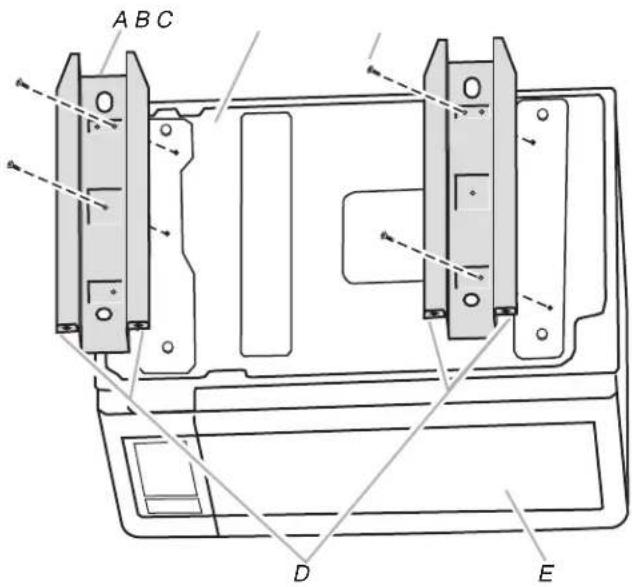
A. Rails (2)
D. Flanges
B. Microwave oven bottom
E. Door
C. Short screws (4)
- Secure the rails to the microwave oven bottom using four short screws.
Attach Rear Duct
- Gently return microwave oven to its upright position.
- Align the rear duct with the back of microwave oven, as shown.
natural_image
Line drawing of a microwave oven with an open lid and ventilation slots, showing internal structure and airflow direction (no text or symbols)- Slide two tabs into the slots on the right side of the back of microwave oven.
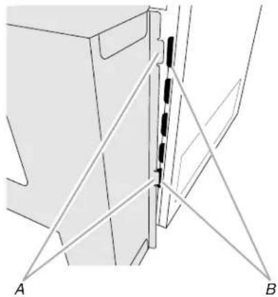
natural_image
Technical line drawing of a mechanical assembly with labeled points A and B (no text or symbols beyond labels)A. Rear duct tabs
B. Slots
- Use two short screws to secure top of rear duct to the back of microwave oven, as shown.
A. Short screws (2)
B. Rear duct
C. Back of microwave oven
- Use three short screws to secure back of rear duct to the back of microwave oven, as shown.
A. Short screws (3)
B. Rear duct
C. Back of microwave oven
Prepare Cutout/Cabinet Opening
- On the cutout floor, find and mark the centerline.
- Place the bottom duct in the opening, with the flange resting against the bottom front facing of the opening.
A. Cutout floor
B. Centerline
C. Bottom duct
D. Bottom duct flange
E. Front facing
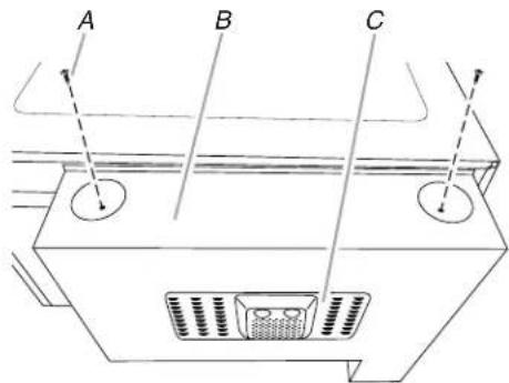
- Align the center arrows on the bottom duct with the centerline drawn in Step 1 above.
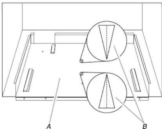
natural_image
Technical line drawing of a mechanical assembly with two circular components labeled A and B, no text or symbols present.A. Bottom duct
B. Center arrows, aligned with centerline
- Mark the three mounting holes through the bottom duct onto the cutout floor.
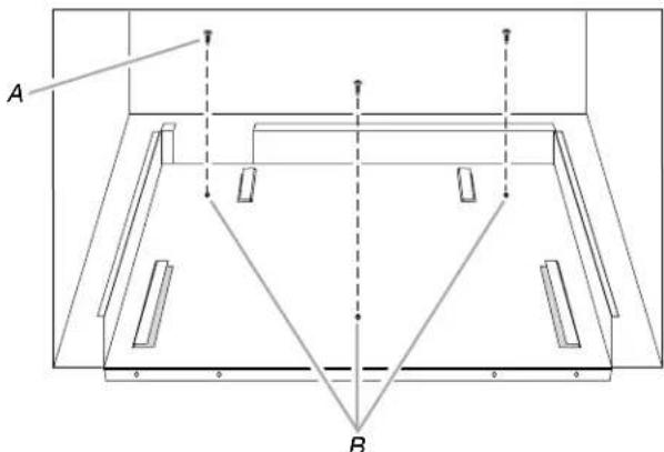
A. Short screws (3)
B. Bottom duct mounting holes
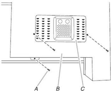
- Using 7/64" drill, drill pilot holes into the three holes marked in Step 4.
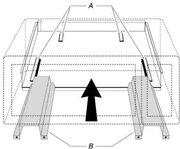
- Realign and install the bottom duct with three short screws.
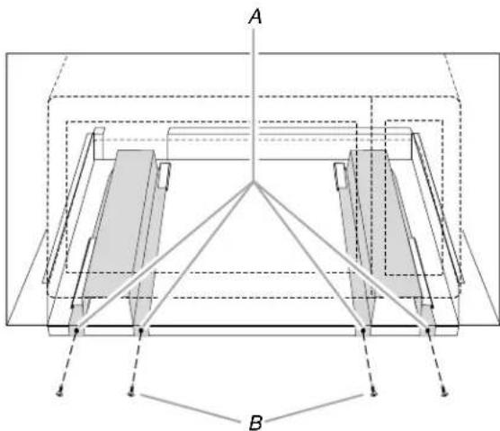
- Using 7/64" drill, drill pilot holes through the four mounting holes of the bottom duct flange into the bottom front facing of the cutout/cabinet opening.
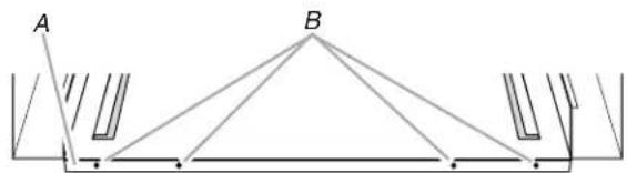
natural_image
Pure geometric diagram showing a triangle with base AB and vertical supports, no text or symbols presentA. Bottom duct flange
B. Mounting holes
Install the Microwave Oven
- Position microwave oven near cutout opening.
WARNING

Electrical Shock Hazard
Plug into a grounded 3 prong outlet.
Do not remove ground prong.
Do not use an adapter.
Do not use an extension cord.
Failure to follow these instructions can result in death, fire, or electrical shock.
-
Plug in microwave oven.
-
Align the rails with the rail guides on the bottom duct.
A. Rail guides
B. Rails
- Slide the microwave oven back and into place. The mounting holes of the rail flanges and bottom duct flange will align against the bottom front facing of the cutout/cabinet opening.
- Secure the microwave oven to the cutout/cabinet by installing four short screws into the mounting holes.
A. Mounting holes
B. Short screws (4)
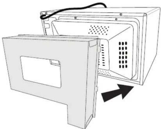
Install Trim Kit Frame
- Position trim kit frame over the opening so that the upper tabs fit inside the rails, as shown.
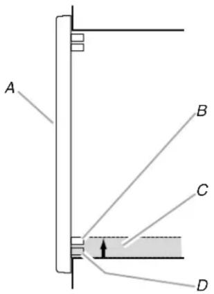
A. Front of trim kit frame
B. Upper tab
C. Rail
D. Lower tab
- To vertically center the trim kit frame, slide it upward, against the opening, until the upper tabs catch against the top of the rails.
- Holding the trim kit frame firmly in place, use 7/64" drill to drill four pilot holes into the front facing of the cutout/cabinet through the mounting hole guides in the upper and lower corners of the trim kit frame.
NOTES:
■ To ensure vertical centering, drill the lower holes first.
■ The holes will be drilled upward from the bottom, and downward from the top at an angle of about 45^ .
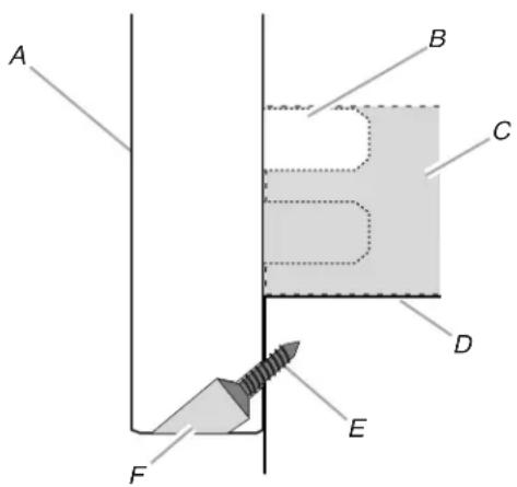
A. Trim kit frame
B. Upper tab
C. Rail
D. Cutout floor
E. Long wood screw (4 - painted)
F. Mounting hole guide
- Secure trim kit frame to cutout/cabinet by installing four long wood screws (painted) into the pilot holes drilled in Step 3 above.
NOTES:
■ To ensure vertical centering, install the lower screws first.
■ To avoid damage to the trim kit frame, do not overtighten screws.
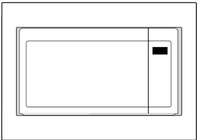
natural_image
Simple line drawing of a rectangular frame with a black square on the side (no text or symbols)Installation is now complete. Replace any loose items that have been removed from microwave oven cavity.
Save these Installation Instructions for future reference.
SÉCURITÉ DU FOUR À MICRO-ONDES
natural_image
Line drawing of a microwave oven with an open lid and ventilation slots, showing internal structure and airflow direction (no text or symbols)natural_image
Technical line drawing of a mechanical assembly with labeled points A and B (no text or symbols beyond labels)natural_image
Technical line drawing of a mechanical assembly with two circular components labeled A and B, no text or symbols present.natural_image
Pure geometric diagram showing two triangles labeled A and B connected to vertical supports (no text or symbols)natural_image
Simple line drawing of a rectangular device with a black square on the side (no text or symbols)
- MICROWAVE OVEN BUILT-IN TRIM KIT INSTALLATION INSTRUCTIONS
- INSTRUCTIONS D'INSTALLATION GARNITURE ENCASTRÉE POUR FOUR À MICRO-ONDES
- Your safety and the safety of others are very important.
- DANGER
- WARNING
- INSTALLATION INSTRUCTIONS
- Tools and Parts
- Tools Needed
- Location Requirements
- Required Cutout Dimensions
- NOTES:
- Electrical Requirements
- Electrical Shock Hazard
- Required:
- Recommended:
- GROUNDING INSTRUCTIONS
- ■ For all cord connected appliances:
- SAVE THESE INSTRUCTIONS
- Prepare Microwave Oven
- Attach Rails
- Attach Rear Duct
- Prepare Cutout/Cabinet Opening
- Install the Microwave Oven
- Install Trim Kit Frame
- SÉCURITÉ DU FOUR À MICRO-ONDES
Brand : MAYTAG
Model : MKC2157AS
Category : Microwave Oven