
CMEW320 - Screwdriver Craftsman - Free user manual and instructions
Find the device manual for free CMEW320 Craftsman in PDF.

| Product type | Table Planer |
| Brand | Craftsman |
| Model | CMEW320 |
| Power supply | 120 V, 60 Hz, 15 A |
| Motor | 15 amps |
| No-load speed | Not specified |
| Max. planing width | 304.8 mm (12 in) |
| Minimum thickness | 12.7 mm (1/2 in) |
| Minimum workpiece length | 304.8 mm (12 in) |
| Max. cutting depth (softwood) | 2.4 mm (3/32 in) up to 203.2 mm (8 in) wide |
| Max. cutting depth (hardwood) | 2.4 mm (3/32 in) up to 203.2 mm (8 in) wide |
| Functions | Planing, jointing, thicknessing |
| Table extensions | 2 removable extensions for infeed and outfeed |
| Maintenance | Clean with dry compressed air, wax the table, lubricate gears and rollers |
| Blade replacement | Reversible double-edged blades, magnetic transfer tool included |
| Safety | Lockable switch, cutter head guard, grounding |
| Warranty | 3-year limited + 90-day satisfaction |
| Included accessories | Handle, 5 mm wrench, blade transfer tool, optional dust chute |
Frequently Asked Questions - CMEW320 Craftsman
User questions about CMEW320 Craftsman
0 question about this device. Answer the ones you know or ask your own.
Ask a new question about this device
Download the instructions for your Screwdriver in PDF format for free! Find your manual CMEW320 - Craftsman and take your electronic device back in hand. On this page are published all the documents necessary for the use of your device. CMEW320 by Craftsman.
USER MANUAL CMEW320 Craftsman
English (original instructions) 1
Definitions: Safety Alert Symbols and Words
This instruction manual uses the following safety alert symbols and words to alert you to hazardous situations and your risk of personal injury or property damage.
DANGER: Indicates an imminently hazardous situation which, if not avoided, will result in death or serious injury.
WITNING: Indicates a potentially hazardous situation which, if not avoided, could result in death or serious injury.
CAITON: Indicates a potentially hazardous situation which, if not avoided, may result in minor or moderate injury.
(Without word) Indicates a safety related message.
NOTICE: Indicates a practice not related to personal injury which, if not avoided, may result in property damage.
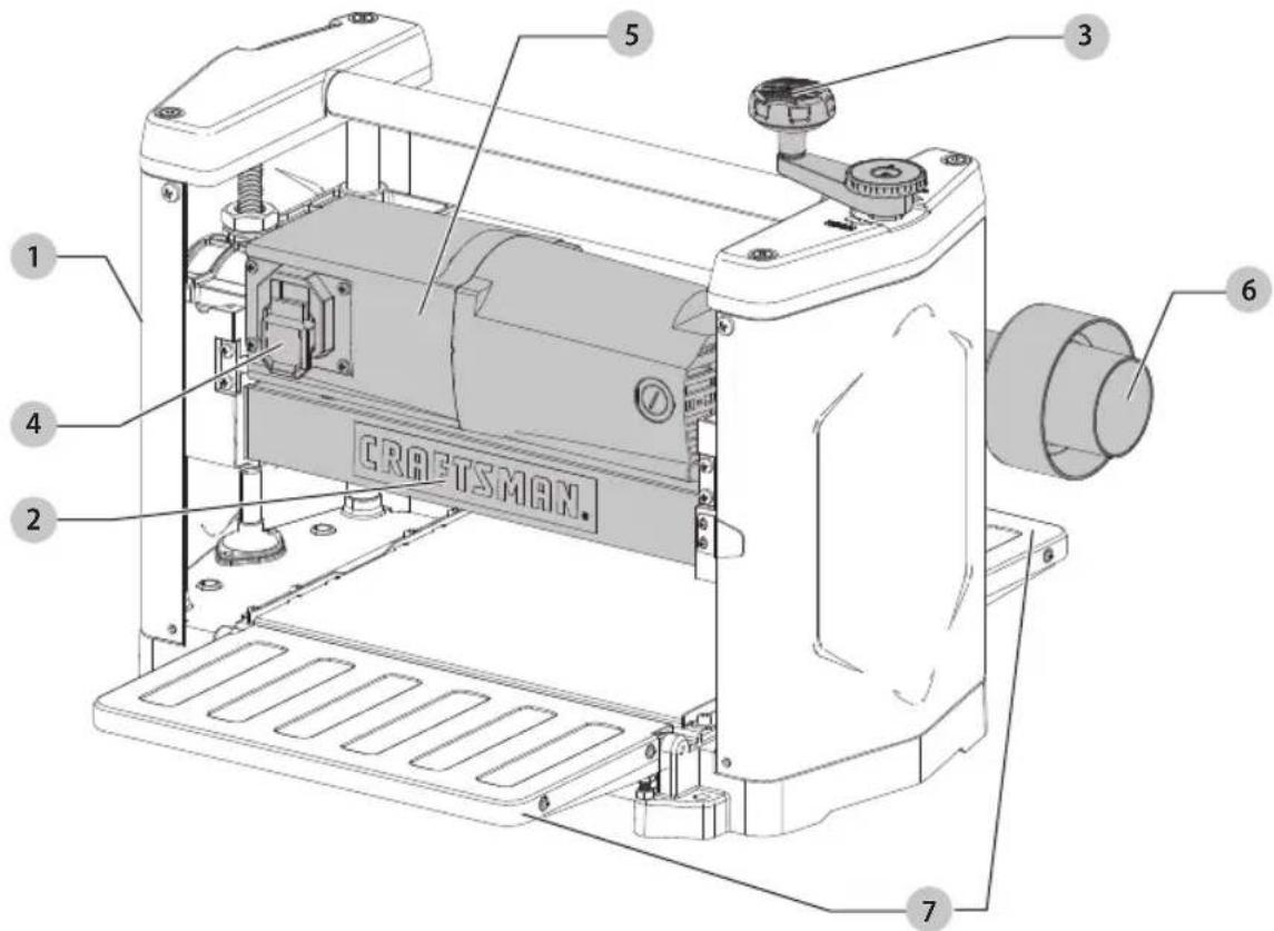
Fig. A
COMPONENTS
1 Planer
2 Cutterhead guard
3 Elevating handle
4 On/Off switch
5 Head assembly
6 Dust chute
7 Infeed/Outfeed extension tables
WARNING: Read all safety warnings and all instructions. Failure to follow the warnings and
instructions may result in electric shock, fire and/or serious injury.

WARNING: To reduce the risk of injury, read the instruction manual.
If you have any questions or comments about this or any product, call CRAFTSMAN toll free at: 1-888-331-4569.
15A Benchtop Planer CMEW320
General Power Tool SafetyWarnings
WARNING: Read all safety warnings, instructions, illustrations and specifications provided with this power tool. Failure to follow all instructions listed below may result in electric shock, fire and/or serious injury.
SAVE ALL WARNING AND INSTRUCTIONS FOR FUTURE REFERENCE
The term "power tool" in the warnings refers to your mains-operated (cored) power tool.
General Safety Instructions
- KEEP GUARDS IN PLACE and in working order.
- REMOVE ADJUSTING KEYS AND WRENCHES. Form habit of checking to see that keys and adjusting wrenches are removed from tool before turning it on.
- KEEP WORK AREA CLEAN. Cluttered areas and benches invite injuries.
- DON'T USE IN DANGEROUS ENVIRONMENT. Don't use power tools in damp or wet locations, or expose them to rain. Keep work area well lighted. Always operate tool in a well-ventilated area free of combustible materials, gasoline or solvent vapors. If sparks come in contact with flammable vapors, they may ignite, causing fire or explosion.
- KEEP CHILDREN AWAY. All visitors should be kept safe distance from work area.
- MAKE WORKSHOP KID PROOF with padlocks, master switches, or by removing starter keys.
- DON'T FORCE TOOL. It will do the job better and safer at the rate for which it was designed.
- USE RIGHT TOOL. Don't force tool or attachment to do a job for which it was not designed.
- USE PROPER EXTENSION CORD. Make sure your extension cord is in good condition. When using an extension cord, be sure to use one heavy enough to carry the current your product will draw. An undersized cord will cause a drop in line voltage resulting in overheating and loss of power. The Minimum Gauge for Cord Sets table shows the correct size to use depending on cord length and nameplate ampere rating. If in doubt, use the next heavier gauge. The smaller the gauge number, the heavier the cord. When operating a power tool outside, use an outdoor extension cord marked "W-A" or "W." These cords are rated for outdoor use and reduce the risk of electric shock.
-
WEAR PROPER APPAREL. Do not wear loose clothing, gloves, neckties, rings, bracelets, or other jewelry which may get caught in moving parts. Nonslip footwear is recommended. Wear protective hair covering to contain long hair. Air vents often cover moving parts and should also be avoided.
-
ALWAYS USE SAFETY GLASSES. Also use face or dust mask if cutting operation is dusty. Everyday eyeglasses only have impact resistant lenses, they are not safety glasses.
- SECURE WORK. Use of clamps or a vis to hold work when practical. It's safer than using your hands and it frees both hands to operate tool.
- DON'T OVERREACH. Keep proper footing and balance at all times.
- MAINTAIN TOOLS WITH CARE. Keep tools sharp and clean for best and safest performance. Follow instructions for lubricating and changing accessories.
- DISCONNECT TOOLS before servicing: when changing accessories, such as blades, bits, cutters, and the like.
- REDUCE THE RISK OF UNINTENTIONAL STARTING. Make sure switch is in off position before plugging in.
- USE RECOMMENDED ACCESSORIES. Consult the instruction manual for recommended accessories. The use of improper accessories may cause risk of injury to persons.
- NEVER STAND ON TOOL. Serious injury could occur if the tool is tipped or if the cutting tool is unintentionally contacted.
- CHECK DAMAGED PARTS. Before further use of the tool, a guard or other part that is damaged should be carefully checked to determine that it will operate properly and perform its intended function—check for alignment of moving parts, binding of moving parts, breakage of parts, mounting, and any other conditions that may affect its operation. A guard or other part that is damaged should be properly repaired or replaced.
- DIRECTION OF FEED. Feed work into planer according to direction of feed arrows on top of the unit.
- NEVER LEAVE TOOL RUNNING UNATTENDED.
TURN POWER OFF. Don't leave tool until it comes to a complete stop.
Safety Rules for Surface Planers
WARNING: Failure to follow these rules may result in serious personal injury.
- Do not operate this machine until it is completely assembled and installed according to the instructions. A machine incorrectly assembled can cause serious injury.
- Obtain advice from your supervisor, instructor, or another qualified person if you are not thoroughly familiar with the operation of this machine. Knowledge is safety.
- Follow all wiring codes and recommended electrical connections to prevent shock or electrocution.
-
Keep knives sharp and free from rust and pitch. Dull or rusted knives work harder and can cause kickback.
-
Never turn the machine "ON" before clearing the table of all objects (tools, scraps of wood, etc.). Flying debris can cause serious injury.
- Never turn the machine "ON" with the workpiece contacting the cutterhead. Kickback can occur.
- Secure the machine to a supporting surface to prevent the machine from sliding, walking or tipping over.
- Be sure that the cutter knives are mounted as described in the instruction manual and check that all bolts are firmly tightened before connecting unit to power source.
- Avoid awkward operations and hand positions. A sudden slip could cause a hand to move into the knives.
- Keep arms, hands, and fingers away from the cutterhead, the chip exhaust opening, and the feed rollers to prevent severe cuts.
- Never reach into the cutterhead area while the machine is running. Your hands can be drawn into the knives.
- Do not stand in line with the workpiece. Kickback can cause injury.
- Allow the cutterhead to reach full speed before feeding a workpiece. Changing speeds while planing can cause kickback.
- When planing bowed stock, place the concave (cup down) side of the stock on the table and cut with the grain to prevent kickback.
- Do not feed a workpiece that is warped, contains knots, or is embedded with foreign objects (nails, staples, etc.). Kickback can occur.
- Do not feed a short, thin, or narrow workpiece into the machine. Your hands can be drawn into the knives and/or the workpiece can be thrown at high speeds. See the Operation section of this instruction manual for details.
- Do not feed a workpiece into the outfeed end of the machine. The workpiece will be thrown out of the opposite side at high speeds.
- Remove shavings only with the power "OFF" and the cutterhead stopped to prevent serious injury.
- Properly support long or wide work pieces. Loss of control of the workpiece can cause serious injury.
- Never perform layout, assembly or set-up work on the table/work area when the machine is running. Serious injury will result.
- Turn the machine "OFF", disconnect it from the power source, and clean the table/work area before leaving the machine. Lock the switch in the "OFF" position to prevent unauthorized use. Someone else might accidentally start the machine and cause injury to themselves or others.
- Additional information regarding the safe and proper operation of power tools (i.e. a safety video) is available from the Power Tool Institute,
1300 Sumner Avenue, Cleveland, OH 44115-2851 (www.powertoolinstitute.com). Information is also available from the National Safety Council, 1121
Spring Lake Drive, Itasca, IL 60143-3201. Please refer to the American National Standards Institute ANSI 01.1 Safety Requirements for Woodworking Machines and the U.S. Department of Labor Regulations.
Supplemental Safety Rules for Planers
- To avoid injury, never rotate the cutterhead directly with your hands.
- Keep hands away from the underside of the cutterhead carriage.
- Never clear clogs, make cutter knife replacement, or any other repairs/adjustments with unit plugged in.
- Make certain that the switch is in the OFF position before connecting plug to a power source.
- Stay alert—never operate the unit when tired or under the influence of drugs, alcohol, or medication.
- Do not use in dangerous environments. Do not use near flammable substances, in damp or wet locations, or expose to rain.
- Never plane material which is shorter than 12^ (304.8 mm) narrower than 3 / 4'' (19.05 mm), or wider than 12^ (304.8 mm) or thinner than 1 / 2'' (12.7 mm).
- Exhaust chute: remove shavings with brush or vacuum after power has been shut off and cutterhead has stopped rotating.
- Always locate planer with proper clearance on the outfeed side of the unit to prevent pinching or binding of the workpiece against any obstacle.
- Never reach into the cutterhead area while the machine is running. Your hands can be drawn into the knives.
- Maintain the proper relationships of infeed and outfeed table surfaces and cutter head knife path.
Additional Safety Information
WARNING: Never modify the product or any part of it. Damage or personal injury could result.
WARNING: ALWAYS use safety glasses. Everyday eyeglasses are NOT safety glasses. Also use face or dust mask if cutting operation is dusty. ALWAYS WEAR CERTIFIED SAFETY EQUIPMENT:
ANSI Z87.1 eye protection (CAN/CSA Z94.3)
ANSI S12.6 (S3.19) hearing protection,
- NIOSH/OSHA/MSHA respiratory protection.
WARNING: Some dust created by power sanding, grinding, drilling, and other construction activities contains chemicals known to the State of California to cause cancer, birth defects or other reproductive harm. Some examples of these chemicals are:
- lead from lead-based paints,
crystalline silica from bricks and cement and other masonry products, and - arsenic and chromium from chemically-treated lumber.
English
Your risk from these exposures varies, depending on how often you do this type of work. To reduce your exposure to these chemicals: work in a well ventilated area, and work with approved safety equipment, such as those dust masks that are specially designed to filter out microscopic particles.
- Avoid prolonged contact with dust from power sanding, sawing, grinding, drilling, and other construction activities. Wear protective clothing and wash exposed areas with soap and water. Allowing dust to get into your mouth, eyes, or lay on the skin may promote absorption of harmful chemicals.
WARNING: Use of this tool can generate and/ or disperse dust, which may cause serious and permanent respiratory or other injury. Always use NIOSH/OSHA approved respiratory protection appropriate for the dust exposure. Direct particles away from face and body.
WARNING: Always wear proper personal hearing protection that conforms to ANSI S12.6 (S3.19)
during use. Under some conditions and duration of use, noise from this product may contribute to hearing loss.
Power Connections
A separate electrical circuit should be used for your machines. This circuit should not be less than #12 wire and should be protected with a 20 Amp time lag fuse.
nOTE: Time delay fuses should be marked "D" in Canada and "T" in the US. If an extension cord is used, use only 3-wire extension cords which have 3-prong grounding type plugs and matching receptacle which will accept the machine's plug. Before connecting the machine to the power line, make sure the switch (or switches) is in the "OFF" position and be sure that the electric current is of the same characteristics as indicated on the machine. All line connections should make good contact. Running on low voltage will damage the machine.
DANGER: Do not expose the machine to rain or operate the machine in damp locations.
MOTOR SPECIFICATIONS
Your machine is wired for 120 Volts, 60 HZ alternating current. Before connecting the machine to the power source, make sure the switch is in the "OFF" position.
Grounding Instructions
DANGER: This machine must be grounded while in use to protect the operator from electric shock.
- All grounded, cord-connected machines:
In the event of a malfunction or breakdown, grounding provides a path of least resistance for electric current to reduce the risk of electric shock. This machine is equipped with an electric cord having an equipment-grounding conductor and a grounding plug. The plug must be plugged into a matching outlet that is properly installed and grounded in accordance with all local codes and ordinances.
- Do not modify the plug provided - if it will not fit the outlet, have the proper outlet installed by a qualified electrician.
- Improper connection of the equipment-grounding conductor can result in risk of electric shock. The conductor with insulation having an outer surface that is green with or without yellow stripes is the equipment-grounding conductor. If repair or replacement of the electric cord or plug is necessary, do not connect the equipment-grounding conductor to a live terminal.
- Check with a qualified electrician or service personnel if the grounding instructions are not completely understood, or if in doubt as to whether the machine is properly grounded.
- Use only 3-wire extension cords that have 3-prong grounding type plugs and matching 3-conductor receptacles that accept the machine's plug.
-
Repair or replace damaged or worn cord immediately.
-
Grounded, cord-connected machines intended for use on a supply circuit having a nominal rating less than 150 volts:
-
If the machine is intended for use on a circuit that has an outlet that looks like the one illustrated in Fig. B, the machine will have a grounding plug that looks like the plug illustrated in Fig. B. A temporary adapter, which looks like the adapter illustrated in Fig. C, may be used to connect this plug to a matching 2-conductor receptacle as shown in Fig. C if a properly grounded outlet is not available. The temporary adapter should be used only until a properly grounded outlet can be installed by a qualified electrician. The green-colored rigid ear, lug, and the like, extending from the adapter must be connected to a permanent ground such as a properly grounded outlet box. Whenever the adapter is used, it must be held in place with a metal screw.
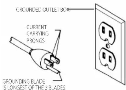
Fig.B
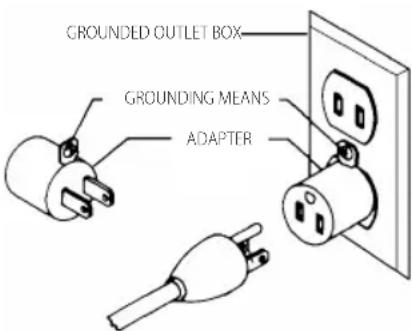
Fig. C
NOTE: In Canada, the use of a temporary adapter is not permitted by the Canadian Electric Code.
DINGER: In all cases, make certain that the receptacle in question is properly grounded. If you are not sure, have a qualified electrician check the receptacle.
EXTENSION CORDS
WARNING: Use proper extension cords. Make sure your extension cord is in good condition and is a 3-wire extension cord which has a 3-prong grounding type plug and matching receptacle which will accept the machine's plug. When using an extension cord, be sure to use one heavy enough to carry the current of the machine. An undersized cord will cause a drop in line voltage, resulting in loss of power and overheating. Minimum Gauge for Cord Sets shows the correct gauge to use depending on the cord length. If in doubt, use the next heavier gauge. The smaller the gauge number, the heavier the cord.
Minimum Gauge for Cord Sets
| Volts | Total Length of Cord in Feet(meters) | ||||
| 120 V 25 (7.6) | 50 (15.2) | 100 (30.5) | 150 (45.7) | ||
| 240 V 50 (15.2) | 100 (30.5) | 200 (61.0) | 300 (91.4) | ||
| Ampere Rating | American Wire Gauge | ||||
| More Than | Not More Than | ||||
| 0.6 18 16 16 14 | |||||
| 6 10 18 16 14 12 | |||||
| 10 12 16 16 14 12 | |||||
12 16 14 12 Not Recommended
The label on your tool may include the following symbols. The symbols and their definitions are as follows:
V volts
Hz .........hertz
min.........minutes
- or DC....direct current
Class I Construction (grounded)
..min..per minute
BPM... .beats per minute
IPM............impacts per minute
RPM.......revolutionsper minute
sfpm.....surface feet per minute
SPM.........strokes per minute
A. amperes
W.....watts
kg.kilograms
mm millimeters
or AC....alternating current
or AC/DC...alternatingordirect current
回............ClassII
Construction (double insulated)
no load speed
n............rated speed
- .earthing terminal
A .safety alert symbol
A visible radiation
wearrespiratory protection
Wc
protection
. wearhearing protection
......readall documentation
SAVE THESE INSTRUCTIONS FOR FUTURE USE
Intended Use
This planer is designed for wood working.
DO NOT use under wet conditions or in presence of flammable liquids or gases.
DO NOT let children come into contact with the tool. Supervision is required when inexperienced operators use this tool.
ASSEMBLY
WARNING: To reduce the risk of serious personal injury, turn unit off and disconnect it from power source before making any adjustments or removing/installing attachments or accessories.
An accidental start-up can cause injury.
Assembly Tools Required
- 5 mm hex wrench (included)
Assembly Time Estimate
Assembly for this machine takes approximately 30 minutes.
Unpacking and Cleaning
Carefully unpack the machine and all loose items from the shipping container(s). Remove the rust-preventative oil from unpainted surfaces using a soft cloth moistened with mineral spirits, paint thinner or denatured alcohol.
NOTICE: Do not use highly volatile solvents such as gasoline, naphtha, acetone or lacquer thinner for cleaning your machine.
After cleaning, cover the unpainted surfaces with a good quality household floor paste wax.
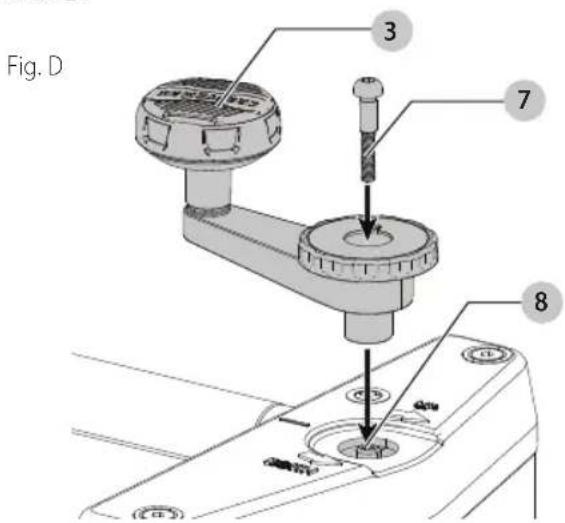
Elevating Handle (Fig. A, D)
Attach the elevating handle 3 to the shaft 8 and fasten in place with M5 x 20 mm screw 7. NOTE: Ensure that the flats of the handle and the flats on the shaft are aligned. Flip handle 3.
English
Lowering Extension Tables (Fig. A)
The infeed and outfeed extension tables 7 are shipped attached to the machine in the raised position. Lower the tables on both sides of the planer. The top surface of extension tables should be level with the planer table. To check and adjust, refer to the section Leveling Extension Tables in this manual.
Fastening Planer to Supporting Surface (Fig. E)
WARNING: The mounting surface should not be mounted or otherwise uneven.
During operation, if there is any tendency for the planer to tip over, slide or "walk" across the supporting surface, the planer must be secured to the supporting surface. Four holes 12 two of which are shown at Fig. E are provided for this purpose.
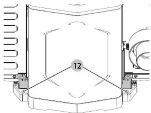
Fig. E
Attaching the Optional Dust Chute (Fig. F)
NOTE: The dust chute is to be attached only when connecting the planer to a dust collection system. Remove the dust chute if the planer is to be used alone to allow for the dust to fall freely out of the planer exhaust.
NOTE: Do not use this planer with a vacuum cleaner or shop vac because the small hose can clog. Only use with a dust collection system using a 4^ (100 mm) hose.
- Align the holes on the dust chute with the threaded holes 28 on the planer housing.
- Insert the provided thumb screws 29 into the holes and tighten securely.
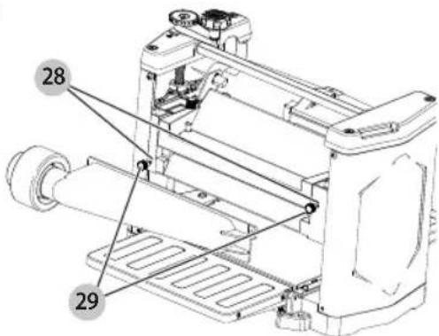
Fig. F
OPERATION
WARNING: To reduce the risk of serious personal injury, turn unit off and disconnect it from power source before making any adjustments or removing/installing attachments or accessories. An accidental start-up can cause injury.
WARNING: Make sure that the cutterhead guard 2 properly secured with the knobs before operating this machine.
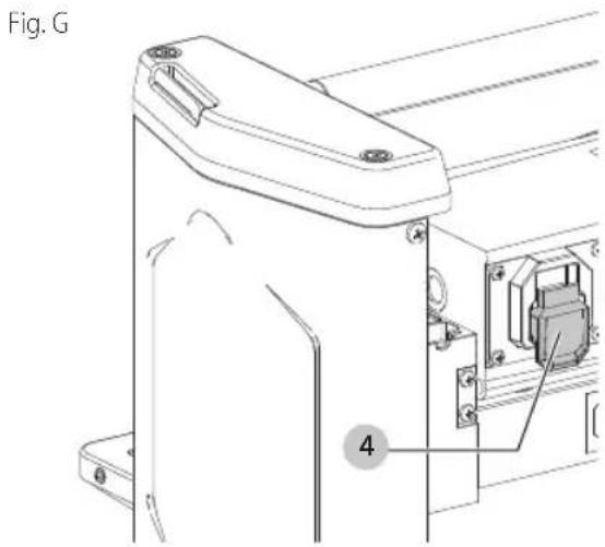
Starting and Stopping Planer (Fig. G, H)
WARNING: Keep hands away from outlet of the head guard. Do not try to use hand to clean dust from outlet.
WARNING: Make sure that the switch is in the "OFF" position before plugging cord into outlet. Do not touch the plug's metal prongs when unplugging or plugging in the cord.
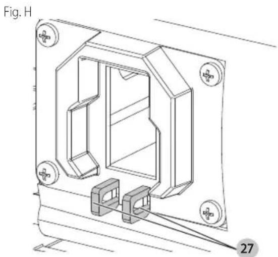
Locking Switch in the "OFF" Position
IMPORTAnT: When the machine is not in use, the switch 4 should be locked in the "OFF" position to prevent unauthorized use. Two holes 27 are provided in the bottom of the switch housing for locking off the planer with a padlock.
WARNING: In the event of a power outage (such as a breaker or fuse trip), always move the switch to the "OFF" position until the main power is restored.
Raising and Lowering Head Assembly (Fig. A)
The head assembly 5 contains the cutterhead feed rollers, cutterhead guard and motor. Raising and lowering the head assembly controls the depth-of-cut on your planer. To raise or lower the head assembly, rotate the handle 3. The handle has height markings to aid in fine adjustments.
NOTE: One revolution of the handle will move the cutterhead up or down approximately 5 / 64^ (2 mm)
An English/metric scale and pointer is located on the front of the planer to indicate the height of the cutterhead.
Adjustment to the pointer can be made by running a piece of wood through the machine. Measure the thickness of the workpiece and if an adjustment is necessary, loosen two screws and adjust pointer accordingly. Then tighten two screws.
Refer to chart for recommended maximum depth-of-cut for various board widths of soft and hard woods.
NOTICE: Continuous operation at the deepest depth of cut can cause premature motor failure.
| MAXIMUM DEPTH-OF-CUT | ||
| Board Width Soft | Woods Hard Woods | |
| 2" (50.8 mm) | 3/32" (2.4 mm) | 3/32" (2.4 mm) |
| 4" (101.6 mm) | 3/32" (2.4 mm) | 3/32" (2.4 mm) |
| 6" (152.4 mm) | 3/32" (2.4 mm) | 3/32" (2.4 mm) |
| 7" (177.8 mm) | 3/32" (2.4 mm) | 3/32" (2.4 mm) |
| 8" (203.2 mm) | 3/32" (2.4 mm) | 3/32" (2.4 mm) |
| 9" (228.6 mm) | 5/64" (2 mm) | 1/16" (1.6 mm) |
| 10" (254 mm) | 1/16" (1.6 mm) | 3/64" (1.2 mm) |
| 11" (279.4 mm) | 1/16" (1.6 mm) | 3/64" (1.2 mm) |
| 12" (304.8 mm) | 1/16" (1.6 mm) | 3/64" (1.2 mm) |
Leveling Extension Tables (Fig. A, I)
The infeed and outfeed extension tables 7 must be level with the planer table. To check the extension tables and adjust if necessary:
-
Place a straight edge 13 on the planer table 14 with one end extending out over the infeed table 12. Check to see if the infeed table is level with the planer table on both ends of the planer table.
-
If an adjustment is necessary, loosen the locknut 16, and adjust the stop screw 17 on each side of the infeed table until the extension table is level with the planer
table. Tighten the locknut. Recheck and make certain that the inside edge of table extension is level with the planer table. If necessary, loosen the two screws 18, adjust the extension table and retighten the two screws. Adjust the opposite side of the table in the same manner. Make certain that the extension table is solidly supported when downward pressure on the table is applied.
- Check and adjust the outfeed table in the same manner.

MACHINE USE
When using your machine, follow these few simple steps for achieving the best results.
- True Up One Face - Feed one face of the board over a jointer, making thin cuts with each pass, until the entire surface is flat.
- Plane to Thickness - Place the side you planed in STEP 1 face down and feed the board through the planer. Plane until this side is flat, then plane both sides of the board until you are satisfied with the thickness. Make thin cuts, and alternate sides with each pass. If, during the planing operation, you notice the board twisting, warping, or bowing, repeat STEP 1 and true up one face.
- When planing long stock, provide table extensions to support the infeed and outfeed end of the workpiece.
- Plane with the grain only, and keep planer table clean. Occasionally, wax the table surface to reduce friction during the planing operation.
- Cross-cut to Final Length - Cross-cut lumber to final length.
CAUTION: The knives on the planer will not wear every if the wood is fed through the same spot on the table every time. Feed the wood through the planer at different spots on the table to help eliminate uneven wear of the knives.
English
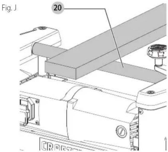
Carrying Handle/Stock Transfer Bar (Fig. J)
- Your planer is provided with a foam covered carrying handle 20, located on top of the machine, for ease in transporting the planer.
- The carrying handle, also doubles as a stock transfer bar for transferring stock from the outfeed to infeed end of the machine. This is helpful when planing long material, as the workpiece can easily be transferred back to the infeed end of the machine for additional cuts.
MAINTENANCE
WARNING: To reduce the risk of serious personal injury, turn unit off and disconnect it from power source before making any adjustments or removing/installing attachments or accessories. An accidental start-up can cause injury.
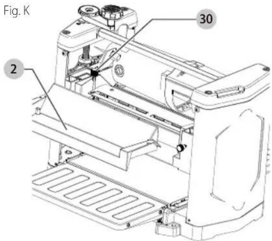
Replacing Knives (Fig. K-M)
WARNING: Make sure that the cutterhead is properly secured with the knobs before operating this machine.
The knives supplied with your planer are double edged and reversible, which enables you to turn the knives end-for-end when one edge becomes dull or chipped. To change the knives, proceed as follows:

- Raise head assembly all the way to the top.
- Remove cutterhead guard 2 by removing two knobs 30.
WARNING: The knives are extremely sharp. Careful when removing, handling or installing knives. Use the knife transfer tool.
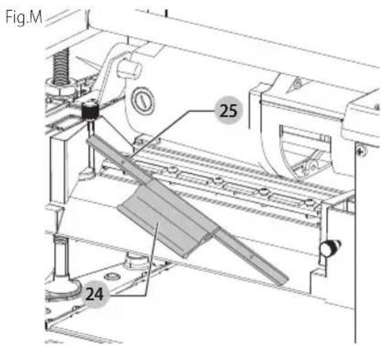
- Using the supplied wrench 31 unscrew the screws at 22, only enough until locking bar 23 separates from knife, allowing knife to be removed.
- Insert knife transfer tool 24, underneath center of knife. Lift the knife transfer tool up until knife 25 separates from pins and pull out and remove knife as shown.
NOTE: Knife transfer tool 24 is magnetized, allowing it to attach to knife.
- Rotate knife end-for-end, or using a new knife, position knife transfer tool on top of knife. Place knife in cutterhead with bevel up underneath locking bar, making sure pins in cutterhead engage with holes in knife.
- Remove knife transfer tool and tighten the six screws using wrench supplied.
- Replace other knife by rotating head 180^ and repeat steps 3 through 6.
- Attach the cutterhead guard to the planer by inserting the end of the guard over the top of the cutterhead. Place the slots in the cutterhead guard over the tapped holes. Fasten cutterhead guard to planer using two knobs.

Cleaning
WARNING: Blow dirt and dust out of all air vents with clean, dry air at least once a week. To minimize the risk of eye injury, always wear ANSI Z87.1 approved eye protection when performing this.
WARNING: Never use solvents or other harsh chemicals for cleaning the non-metallic parts of the tool. These chemicals may weaken the plastic materials used in these parts. Use a cloth dampened only with water and mild soap. Never let any liquid get inside the tool; never immerse any part of the tool into a liquid.
Keep Machine Clean
Periodically blow out all air passages with dry compressed air. All plastic parts should be cleaned with a soft damp cloth. NEVER use solvents to clean plastic parts. They could possibly dissolve or otherwise damage the material.
WARNING: Wear certified safety equipment for eye, hearing and respiratory protection while using compressed air.
Failure To Start
Should your machine fail to start, check to make sure the prongs on the cord plug are making good contact in the outlet. Also, check for blown fuses or open circuit breakers in the line.
Lubrication & Rust Protection
Apply household floor paste wax to the planer table, extension table or other work surface weekly. Or use a commercially available protective product designed for this purpose. Follow the manufacturer's instructions for use and safety.
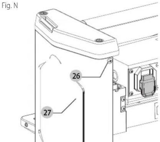
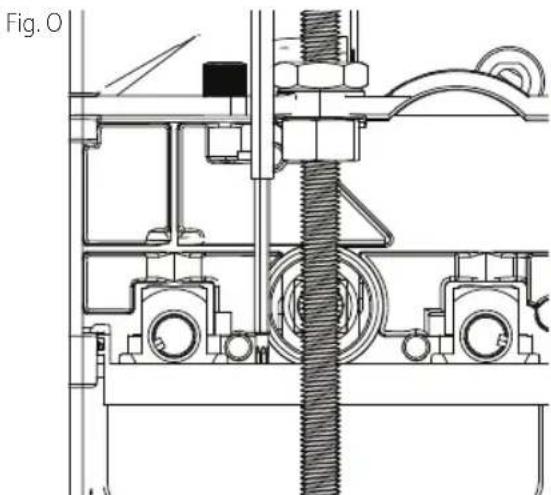
Lubrication (Fig. N, 0)
The gears in the gear box and the feed roller bushings should be lubricated periodically.
W P R N I N G: Disconnect tool from power source.
- Remove the screw 26 and nut located on the other end of screw. Remove the side cover 27 from the left side of the planer.
- Place a light coat of E.P. multi-purpose grease on the teeth of the gears, and a light coat of spray lubricant on the chains. Replace the side cover.
- Place the planer on its back and squirt oil on the feed roller bushings at each end of the feed rollers.
- Replace side cover.
Accessories
WARNING: Since accessories, other than those used by CRAFTSMAN, have not been tested with this product, use of such accessories with this tool could be hazardous. To reduce the risk of injury, only CRAFTSMAN recommended accessories should be used with this product.
Recommended accessories for use with your tool are available at extra cost from your local dealer or authorized service center. If you need assistance in locating any accessory, please contact CRAFTSMAN, call 1-888-331-4569.
ENGLISH
Storage
Knife Transfer Tool Storage
The knife transfer tool supplied with your planer, can easily be stored underneath the outfeed table extension when not being used. A velcro strip is provided on the tool and underneath the table for this purpose.
Wrench Storage (Fig. P)
The wrench 31, can be stored in hole 19 located on the right rear side of the machine as shown.
Fig.P

Register Online
Thank you for your purchase. Register your product now for:
WARRANTY SERVICE: Registering your product will help you obtain more efficient warranty service in case there is a problem with your product.
CONFIRMATION OF OWNERSHIP: In case of an insurance loss, such as fire, flood or theft, your registration of ownership will serve as your proof of purchase.
FOR YOUR SAFETY: Registering your product will allow us to contact you in the unlikely event a safety notification is required under the Federal Consumer Safety Act.
Register online at www.craftsman.com/
Three Year Limited Warranty
CRAFTSMAN will repair or replace, without charge, any defects due to faulty materials or workmanship for three years from the date of purchase. This warranty does not cover part failure due to normal wear or tool abuse. For further detail of warranty coverage and warranty repair information, visit www.craftsman.com or call
1-888-331-4569. This warranty does not apply to accessories or damage caused where repairs have been made or attempted by others. THIS LIMITED WARRANTY IS GIVEN IN LIEU OF ALL OTHERS, INCLUDING THE IMPLIED WARRANTY OF MERCHANTABILITY AND FITNESS FOR A PARTICULAR PURPOSE, AND EXCLUDING ALL INCIDENTAL OR CONSEQUENTIAL DAMAGES. Some states do not allow limitations on how long an implied warranty lasts or the exclusion or limitation of incidental or consequential
damages, so these limitations may not apply to you. This warranty gives you specific legal rights and you may have other rights which vary in certain states or provinces.
90 DAY MONEY BACK GUARANTEE
If you are not completely satisfied with the performance of your CRAFTSMAN Power Tool or Nailer for any reason, you can return it within 90 days from the date of purchase with a receipt for a full refund - no questions asked.
LATIN AMERICA: This warranty does not apply to products sold in Latin America. For products sold in Latin America, see country specific warranty information contained in the packaging, call the local company or see website for warranty information.
FREE WARNING LABEL REPLACEMENT: If your warning labels become illegible or are missing, call 1-888-331-4569 for a free replacement.
Lubrification (Fig. N, O)
REEMPLACEMENT Gratisuit DES ETIQUETTES


- Definitions: Safety Alert Symbols and Words
- COMPONENTS
- WARNING: Read all safety warnings and all instructions. Failure to follow the warnings and
- 15A Benchtop Planer CMEW320
- General Power Tool SafetyWarnings
- SAVE ALL WARNING AND INSTRUCTIONS FOR FUTURE REFERENCE
- General Safety Instructions
- Safety Rules for Surface Planers
- Supplemental Safety Rules for Planers
- Additional Safety Information
- English
- Power Connections
- MOTOR SPECIFICATIONS
- Grounding Instructions
- EXTENSION CORDS
- SAVE THESE INSTRUCTIONS FOR FUTURE USE
- Intended Use
- ASSEMBLY
- Assembly Tools Required
- Assembly Time Estimate
- Unpacking and Cleaning
- Elevating Handle (Fig. A, D)
- Lowering Extension Tables (Fig. A)
- Fastening Planer to Supporting Surface (Fig. E)
- Attaching the Optional Dust Chute (Fig. F)
- OPERATION
- Starting and Stopping Planer (Fig. G, H)
- Locking Switch in the "OFF" Position
- Raising and Lowering Head Assembly (Fig. A)
- Leveling Extension Tables (Fig. A, I)
- MACHINE USE
- Carrying Handle/Stock Transfer Bar (Fig. J)
- MAINTENANCE
- Replacing Knives (Fig. K-M)
- Cleaning
- Keep Machine Clean
- Failure To Start
- Lubrication & Rust Protection
- Lubrication (Fig. N, 0)
- Accessories
- Storage
- Knife Transfer Tool Storage
- Wrench Storage (Fig. P)
- Register Online
- Three Year Limited Warranty
- DAY MONEY BACK GUARANTEE
- Lubrification (Fig. N, O)
- REEMPLACEMENT Gratisuit DES ETIQUETTES
Brand : Craftsman
Model : CMEW320
Category : Screwdriver