
CMKGAAV45099000 - Lawn mower Craftsman - Free user manual and instructions
Find the device manual for free CMKGAAV45099000 Craftsman in PDF.

| Product Type | Riding Lawn Mower Lift |
| Brand | Craftsman |
| Model | CMKGAAV45099000 |
| Maximum Load Capacity | 226 kg (500 lb) |
| Compatible Wheel Diameter | 25 to 43 cm (10 to 17 inches) |
| Adjustable Track Width | 80 to 158 cm (31.5 to 67.5 inches) |
| Main Material | Steel |
| Usage | Lift front of mower for maintenance |
| Power Source | Manual (crank) or optionally with drill |
| Safety | Safety straps, locking pin, wheel chocks, safety clutch system |
| Maintenance | Clean and oil threads every 50 uses or once a year; grease bearing and handle pivot |
| Warranty | Limited 2-year; 90-day money-back guarantee |
| Country of Manufacture | United States and Canada |
| Included Accessories | 2 safety straps, 2 wheel supports, crank, pins, axles |
| Approximate Weight | About 15-20 kg (estimate) |
| Dimensions (Assembled) | Not provided, but designed for vertical storage |
| Repairability | Spare parts available via Craftsman customer service |
Frequently Asked Questions - CMKGAAV45099000 Craftsman
User questions about CMKGAAV45099000 Craftsman
0 question about this device. Answer the ones you know or ask your own.
Ask a new question about this device
Download the instructions for your Lawn mower in PDF format for free! Find your manual CMKGAAV45099000 - Craftsman and take your electronic device back in hand. On this page are published all the documents necessary for the use of your device. CMKGAAV45099000 by Craftsman.
USER MANUAL CMKGAAV45099000 Craftsman
Definitions: Safety Alert Symbols and Words
This instruction manual uses the following safety alert symbols and words to alert you to hazardous situations and your risk of personal injury or property damage.

DANGER: indicates an immeently hazardous situation which, if not avoided, will result in death or serious injury.

WARNING: indicates an potentially hazardous situation which, if not avoided, could result in death or serious injury.

CAUTION: indicates an potentially hazardous situation which, if not avoided, may result in minor or moderate injury.

(Used without word) Indicates a safety related message.
NOTICE: indicates a practice not related to personal injury which, if not avoided, may result in property damage.
natural_image
Mechanical support system with articulated arms and a diagonal line (no visible text or symbols)
WARNING: Read all safety warnings and all instructions. Failure to follow the warnings and instructions may result in serious injury and/or death.

WARNING: Never modify the product or any part of it. Damage or personal injury could result. WARNING: To reduce the risk of injury, read the instruction manual.
FREE WARNING LABEL REPLACEMENT: If your warning label's become illegible or are missing, call 1-888-331-4569 for a free replacement.

natural_image
Mechanical component diagram showing a lever mechanism with no visible text or symbols
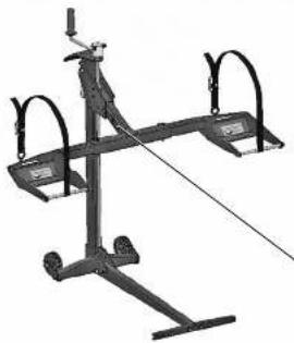
Riding Mower Lift
CMKGAAV45099000
Warning and Safety Instructions
WARNING: To reduce the risk of personal injury:
Read and understand at safety and operating instructions before using the mower life. K-22 THESE INSULCTIONS FOR FUTURE REFERENCE
- Never allow anyone unfamiliar with the safety or operating instructions to use the lift.
- Follow all safety and servicing instructions provided by the own owner's manufacturer before using the lift.
- Do not modify the lift in any way. Any modifications will void any and all warranties and could compromise your personal safety.
- When using the fit, keep A bystanders at a safe distance away from the mower fit.
- The lift must be used on a solid level surface.
- Only lift the FRONT end on the power
- Do not lif, the front end end back end of the mower at the same time.
- Only use the lift for mowers that are less than 500 lbs (226 kg) front end weight and properly fits in the provided wheel pods tie. 10" to 17" diameter and within outside wheel measurements of 31.5" to 62.5".
• Always stop engine and remove key before beginning any work on the mower.
• Always place mower in neutral or disengage the hydraulic drive by following the newer instruction manual.
- Never operate the engine while using the power lift
• Do not exceed the lifting capacity of 500 lbs. (225 kg) front end weight.
- If the lift, lower is leaning while lifting or lowering the mower, this indicates an overload condition. REMOVE THE MOWER IMMEDIATELY
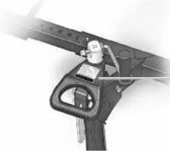
- Tower must be secured in place with the Tower Clevis Fin before using the lift.
- Carer locking Handle must be locked into Tower before starting any service on mower
- Do not remove safety warnings or decals from lift.
Before each use, always check for any worn, loose or damaged parts on the lift. If any damaged parts are present, do not use the lift.
- Do not climb on mower while it is lifted, being lifted or being lowered
- No one should be on the mower while it is lifted, being lifted or being lowered.
• After the mower is raised to a working height, always place wheel checks (not included) behind the back sizes of the mower.
- Wheel Rads must be equal distance from the lift Arm to maintain proper balance.
- Always secure front mower tires with enclosed safety straps.
- Remove all mower attachments before using the lift. Remove all front mower attachments (ballast, bumper or brush guard; that interferes with handle before using the lift.
- Some owners which are equipped with a fuel tank vent may spill fuel when lifted. If this happens, run fuel level down in the tank to prevent selling.
• Always use proper personal protection equipment.
- Failure to follow these warnings may result in property damage and serious body injury or death.
IMPORTANT: The newer life is intended for use with moreers only. Do not exceed 500 lbs. (226 kg) from end weight. It should never be used to service other types of machinery unless there is an approved accessory fated for the type of machinery.
ENGLISH
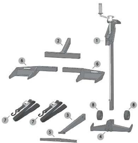
| Item No. | Part No. | Qty. | Description |
| 1 | 509-0014 | 1 | Tower Assembly |
| 2 | 509-0026 | 1 | Lift Arm |
| 3 | 509-0033 | 1 | Base Floor Tube |
| 4 | 509-0048 | 1 | Base |
| 5 | 509-0036 | 1 | Base Support Channel |
| 6 | 500-0039 | 2 | Wheel Pad |
| 7 | 000 0007 | 2 | Safety Scrap |
| 8 | 010 0013 | 2 | Wheels |
WARNING: Read all safety warnings and all instructions. Failure to follow the warnings and instructions may result in serious injury and/or death.
WARNING: Never modify the product or any part of it. Damage or personal injury could result.
WARNING: To reduce the risk of injury, read the instruction manual.
If you have any questions or comments about this or any product, call CRAFTSMAN toll free at: 1-888-331-4569.
ENGLISH
Hardware ListParts List
| Item No. | Part No. | Qty. | Description |
| 9 | 509-0040 | 2 | Wheel Pad Support Rod |
| 10 | 003-0005 | 2 | Flange Head Bolt M10-1.5 X 60 |
| 11 | 003-0016 | 2 | Flange Head Bolt M10-1.5 X 65 |
| 12 | 003-0007 | 2 | Flange Head Bolt M8-1.25 X '6 |
| 13 | 002-0001 | 4 | Nylon Lock Nut - M10-1.5 |
| 14 | 001-0014 | 4 | Washer M10 |
| 15 | 002-0008 | 2 | Nut - M10 |
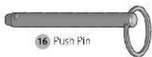
| 16 | 001-0013 | 2 | Push Pin |
| 17 | 001-0012 | 2 | Clovis Pin |
| 18 | 001-0010 | 4 | Hair Pin |

9 Wheel Pad Support Rod
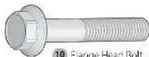
10 Flange Head Bolt
M10 15 X 60
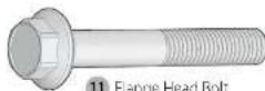
11 Flange Head Bolt
M10 15 X 65
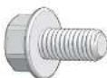
12 Flange Head Bolt
M8-1.25 X 16

13 Nylon Lock Nut M10-1.5

14 Washer M10

15 NutM10
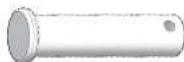
17 Clevis Pin
18 Hair Pin
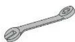
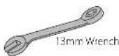
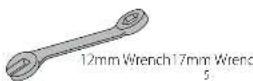
Tools Needed for Assembly (not included)
ENGLISH
Assembly Instructions
STEP 1
Remove fit from package.
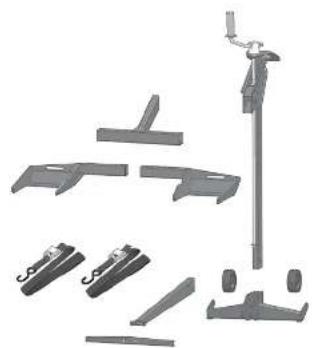
Inventory items to be certain all parts and hardware are present. If any parts or hardware are missing, please contact Molack at 1-877-575-3173 or email us at parts@thermojack.com.
natural_image
Collection of mechanical components including clamps, hooks, and a vertical pole (no text or symbols visible)STEP 2
Assemble the Wheel 8 to the Base 4 by inserting Flange Bolt 11 through the wheel and threading the Nut 15. Insert Flange Bolt through the Base, add Washer 14 and secure with Nylock Nut Repeat with second Wheel.
Note: Do not over tighten Nylon Look Nut.

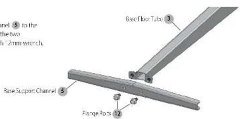
STEP 3
Assemble the Base Support Channel 5 to the Base Floor Tube 3 by inserting the two Flange Bolts 12 and tighten with 12mm wrench.
6
ENGLISH
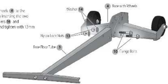
STEP 4
Assemble Base with Wheels 4 to the Base Floor Tube 3 by inserting the two Flange Bolts 10, Washers 14 and Nylon Lock Nuts 13 and tighten with 13mm wrenches.
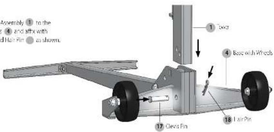
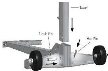
STEP 5
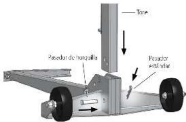
Insert the Tower Assembly 1 to the Base with Wheels 4 and affx with Clevis Pin 17 18nd Hal-Fin as shown.
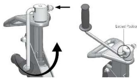
STEP 6
Push in side of handle and rotate from storage position to the operating position. Allow to seat into the locked position.
7
ENGLISH
ENGLISH
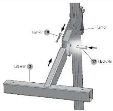
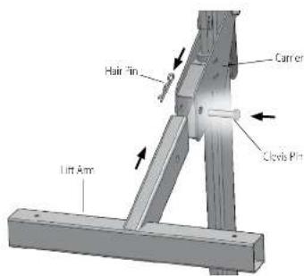
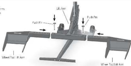
STEP 7
Insert the Lift Arm 2 into the Carrier and insert the Clevis Pin 17. Through the hole in Carrier and lock by fastening the Hair Pin 18 to the Clevis Pin.
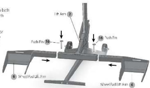
STEP 8
Slide the Wheel Pad Lift Arms 6 onto both sides of the Lift Arm 2 and secure with Push Pins 16.
NOTE: The Wheel Pods can be moved in or out to fit different move widths. Use the configuration that works best with your model of lawn move.
NOTE: The Safety Straps must be used during operation (see Step 9 of the Operating instructions).

WARNING: Wheel posts must be equal distance from the Lift Arm to maintain proper balance. For additional information, see see Step 6 of the Operating instructions.
THIS COMPLETES ASSEMBLY.
Operating Instructions
Some steps of the Operating Instructions are repeated from the Assembly Instructions. The Operating Instructions will show a full working cycle of the mower lift.
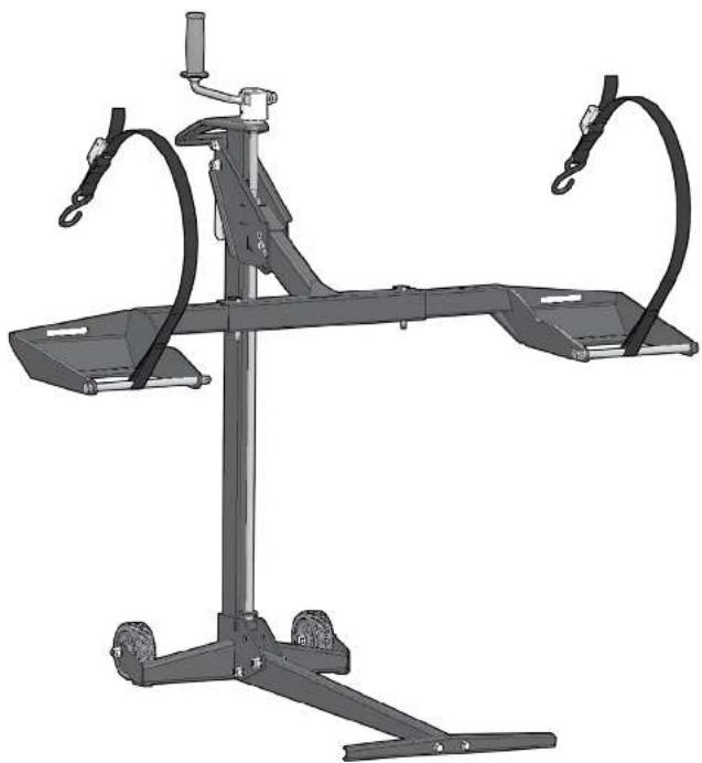
natural_image
Mechanical support system with articulated arms and wheels (no text or symbols visible)
Before using the mower lift, carefully read this manual in its entirety.
ENGLISH
Preparing for Use (Steps 1 - 7)
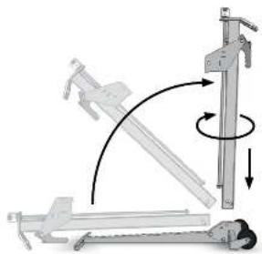
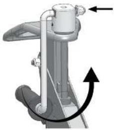
STEP 1
Unfolding the Mower Lift (if not applicable, skip to Step 2) - Remove Hair Pin and Clevis Pin from the Wheel Frame - Remove the Tower out of the Wheel Frame - Rotate Tower 180 degrees and Insert into Wheel Frame - Secure the Tower to the Wheel Frame by Inserting Clevis Pin and Hair Pin.
natural_image
Mechanical assembly diagram showing a lever mechanism with rotational motion arrows (no text or symbols)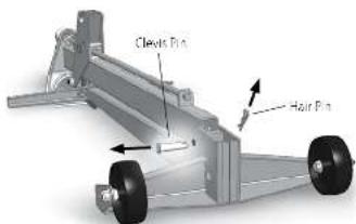
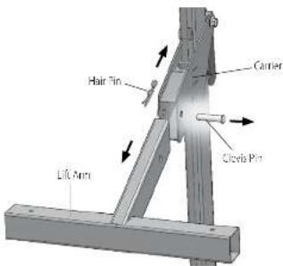
STEP 2
Installing Lift Arm - Insert the Lift Arm into the Carrier and insert the Clevis Pin through the hole in Carrier and lock by fastening the Hair Pin to the Clevis Pin
0
ENGLISH
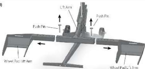
STEP 3
Installing Wheel Pad Lift Arms • Slide Wheel Pad Lift Arms into both sides of the Lift Arm and secure with Push Pins.
STEP 4
Preparing the handle • Push in side of handle and rotate from storage position to the operating position. Allow to seat into the locked position.
natural_image
Mechanical assembly diagram showing a rotating component with directional arrows (no text or symbols)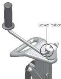
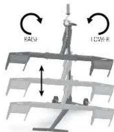
STEP 5
Familiarize yourself with the jack. • Practice raising and lowering the Lift Arm before attempting to lift the mower (see Steps 10 – 13 on how to raise and lower the Lift Arm). • Practice Step 15 if you intend to raise or lower the mower with a drill at Lachmori.
NOTE: Remove all from drawer attachments that interfere with handle before using the lift.

WARNING: When using the lift, keep Air bystanders at a safe distance away from the mower lift.
11
ENGLISH
ENGLISH
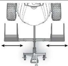
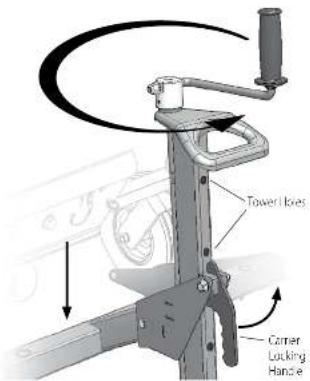
STEP 6
Aligning Wheel Pads to Fit Mower
- Position the jack in front of the mower.
- Remove Push Pins and adjust the wheel pad to align with
the mower's front tires.
- Replace the Push Pins to lock the Wheel Pad Lift Arms to
the Lift Arm.

WARNING: Wheel Pod Lift Arms must be equal distance from the
Lift Arm to maintain proper balance
natural_image
Top-down schematic of a vehicle suspension system with two wheels and support structures (no text or labels)STEP 7
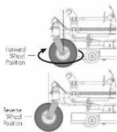
(optional) - if not applicable, step to Step 8)
In some cases, the mower deck or anti-scalping wheels will hit the lift. Arm while the mower is being raised. This is often the case if part of the deck (including the anti-scalping wheels) provides past the center line of the front wheels of the mower. If this happens:
- Rotate the front tires 180^ so that they are in the reverse position.
- Slide the lift as close to the wheels as possible.
NOTE: Reference Step 6 for Aligning Wheel Pads to fit ZTR mower.
Using the Lift (Steps 8 - 15)
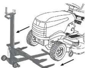
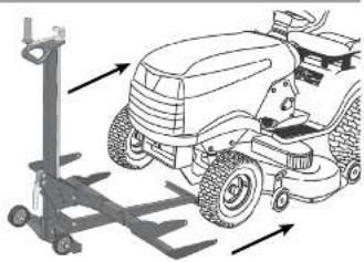
STEP 8
Move move onto jack

WARNING: The jack must be used on a solid level surface.

or to The winner onto the Wheel Pads.

WARNING: Stop engine and remove the key.
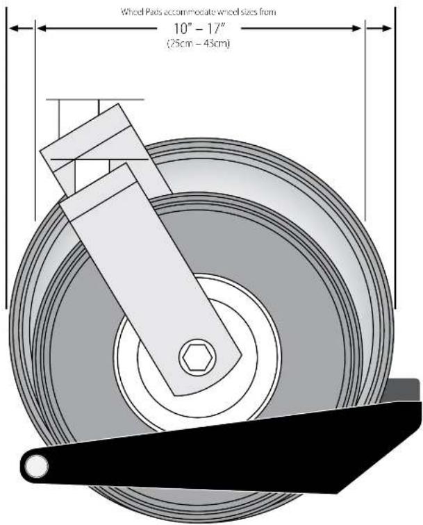
NOTE: Wheel Pads accommodate wheel sizes from 10°-17° (25cm-43cm).

WARNING: Not for use with tires over 17"
(43cm) in size.
natural_image
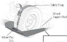
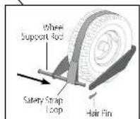
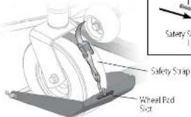
Diagram of a grassy tractor with wheels and suspension system, showing mechanical components and motion arrows (no text or symbols)STEP 9
Strapping From Mower Tires to Wheel Pads
- Secure the front, mower lines to the Wheel Pads using the Safety Straps. Secure the hook on the Safety Strap to the Wheel Pad S or. The Safety Strap hook should always be facing upward.
- Extend the Safety Strap over the top of tire.
- Insert the Wheel Support Rod through one hole on the Wheel Pad, through the loop on the Safety Strap and through the other side of the Wheel Pad. Secure with Large Hall Pin.
- Squeeze the metal buckle and pull end of scrap to tighten the Safety Straps over the top of the tires to secure power to Wheel Pads.
NOTE: Inspect Safety Strap for wear before each use.

WARNING: Always secure front mower tires
with enclosed safety straps.
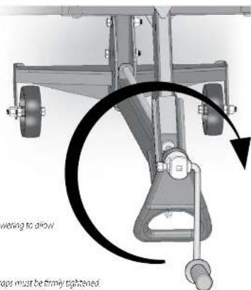
STEP 10
Raising the Mower
- Raise the mower by rotating the Crank Handle clockwise.
- See Step 15 for raising the mower with drill attachment.
NOTE: Mower deck must be raised to highest setting.

WARNING: Do not exceed the lifting capacity of 500 lbs.
(25 kg) from end weight

WARNING: If the lift Tower is leaning while lifting or lowering the mower, this indicates an overload condition. REMOVE THE MOWER IMMAHIXATHY.

WARNING: The jack must be used on a solid level surface.

WARNING: The engine must be turned off and key removed.

WARNING: The mower must be in neutral when raising or lowering to allow the wheels roll as the mower is raised or lowered.

WARNING: The parking brake must be off during this step.

WARNING: Always use attached safety straps. The Safety Straps must be firmly tightened
2
ENGLISH
ENGLISH
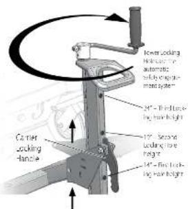
STEP 11
Raising Lift Arm to Locking Position
- Raise the Lift Arm until the Carrier Locking - tend to drops into one of the three Tower Holes. The Tower Locking Holes are the automatic safety engagement system.
- The Carrier Locking Handle automatically drops into the Tower I loles as the Carrier passes the Tower I loles when raising. Locking engagement occurs at 14°, 19° and 24°.
NOTE: When lowering the Lift Arm, the Carrier Locking Handle must be held out by the operator until it clears the bottom Tower Hole.
NOTE: The lift is equipped with a clutch to protect itself from accidental damage. If the Carrier Locking Handle is not disengaged when lowering, the clutch will release the Crank Handle from the screw and rotate freely. To re-engage the Crank Handle, turn clockwise for a few turns.
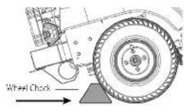
STEP 12
Preparing the Mover for Service
- Place wheel chocks (not included) behind the back tires of the mower.
- Apply the parking brake on the mower.
- The Camer Locking Handle must be locked into one of the two lower holes.
STEP 13
Lowering the Mower
- Remove wheel checks
- Release the parking brake.
- Mower must be in neutral or hydraulic drive disengaged.
- Pu land hold the Carrier Locking Handle out and turn the Crank Handle counter clockwise until Whee Pads are firmly on the ground.
NOTE: The Carrier Locking Handle must be pulled out until it clears the bottom lower Hole, it may be necessary to raise the Carrier slightly to allow the Carrier Locking Handle to be pulled out.
NOTE: The lift is equipped with a clutch to protect itself from accidental damage. If the Carrier Locking Handle is not disengaged when lowering, the clutch will release the Crank Handle from the screw and rotate freely. To re-engage the Crank Handle, turn clockwise for a few turns.
STEP 14
Removing the mower from the lift.
- Remove the Safety Straps from front mower tires.
• Drive or roll the money of the Wheel Backs
STEP 15
Raising the lift with a power drill
(optional - power drill not included)
The lift can be raised or lowered by using a variable speed corded drill (2 amp minimum) or variable speed cordless drill (18V minimum). The drill will require a 3/8" square driver (not included).
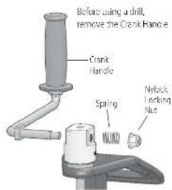
- Remove Crank Handle by taking off the Nylon Lock Nut and Spring using 13mm wrench.
After Crank Handle removal, re-attach Spring and Nylon Lock Nut to Crank Handle to prevent loss.
- Firmly insert the 3/8" square driver in the Square Receiver. Rotate the drill forward (clockwise) to raise the Lift Arm and rotate the drill in reverse (counterclockwise) to lower the Lift Arm.
NOTE: Camer Locking Handle must be manually pulled out when lowering until it clears the bottom lower Hole.

WARNING: Operator must have a firm grip on the drill before raising or lowering the Lift Arm.
NOTE: Crank Handle must be removed in order to use the drill attachment.
Follow all other operating instructions while using the drill
attachment. Replace the Crank Handle as necessary for future use.
NOTE: When re-assembling handle, take care not to over tighten the Nylon Lock Not against the spring. There should be enough free space for the handle to be pushed in to move from storage position to operating position.
NOTE: When re-assembling the handle, a "popping" sound may occur due to the re-engagement of the clutch system.
natural_image
Technical line drawing of a grass lawn tractor with support structure (no text or symbols)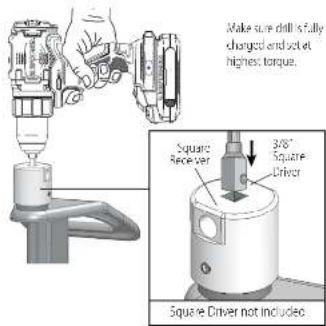
4
5
ENGLISH
Preparing for Storage (Steps 16 - 20)
STEP 16
Removing the Wheel Pacs
- Remove Push Pins and
pull the Wheel Pad
Lift Arms out of the
Lift Arm.
- Store the Push Pins
in the Lift Arm to
prevent loss
STEP 17
Removing the Lift Arm
- While holding the Hill Arm, remove the
Hair Pin and Clevis Pin from Lift Arm.
- Slide the Lift Arm out of the Carrier
- Store the Hair Pin and Clevis Pin in the Lift Arm to prevent loss.
STEP 18
Raise Carrier
- Raise the Carrier by turning the Crank Handle clockwise
until the Carrier Locking Handle drops into the top Lower Hole.
6
ENGLISH
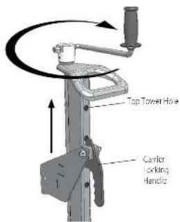
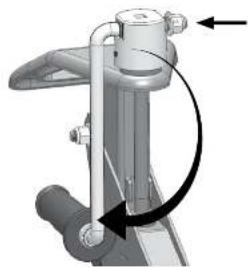
STEP 19
Rotate Crank Handle to Storage position
- Push in side of handle and rotate from operating position to the
storage position. Allow to seat into the locked position.
natural_image
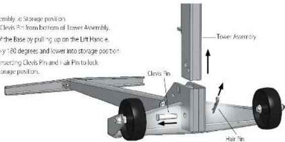
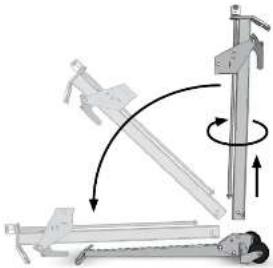
Mechanical assembly diagram showing a lever mechanism with arrows indicating motion direction (no text or symbols)STEP 20
Moving the Lower Assembly to Storage position
- Remove Hair Pin and Clevis Pin from bottom of Tower Assembly.
- Raise the Tower out of the Base by pulling up on the Lift Hang e.
- Rotate Tower Assembly 180 degrees and lower into storage position.
- Secure the Tower by inserting Clevis Pin and Pair Pin to lock
Power Assembly in storage position
natural_image
Illustration of a person performing a leg raise exercise with a vertical pole and arm mechanism (no text or symbols)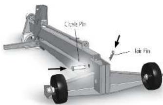
Supported Tire Sizes

WARNING: Not for use with tires over 17" (43cm) in size.
8
ENGLISH
Maintenance Schedule
- Before each use, always check for any worn, loose or damaged parts on the lift. If any damaged parts are present, do not use the lift
- Clean and oil the entire screw thread after every fifty (50) uses or at least once a year using light machine oil.
- Place Tinium grease between the Crank Handle Base and the brass bearing after every fifty (50) uses or once a year. Without weight on carrier, lift the Crank Handle to create a small gap between the brass bearing and the Crank Handle Base. Use a small brush to apply the Tinium grease between the two surfaces,
- Spray grease or tube in Carrier Locking Handle pivot after every fifty (50) uses or at least once a year.
- Wipe clean and lightly apply grease to front and back of Tower Assembly after every fifty (50) uses or at least once a year.

Register Online
Thank you for your purchase. Register your product now for
- WARRANTY SERVICE: Registering your product will help you obtain more efficient warranty service in case there is a problem with your product.
- CONFIRMATION OF OWNERSHIP: In case of an insurance loss, such as fire, flood or theft, your registration of ownership will serve as your proof of purchase.
• FOR YOUR SAFETY: Regstering your product will allow us to contact you in the unlikely event a safety notification is required under the Federal Consumer Safety Act.
Register online at www.craftsman.com/registration
Two Year Limited Warranty
CRATSMAN will repair or replace, without charge any defects due to faulty materials or workmanship for two years from the date of purchase. This warranty does not cover part failure due to normal wear or tool blouse. For further detail of warranty coverage and warranty repair information, visit www.craftsman.org or call 1-888-311-1569. This warranty does not apply to accessories or damage caused where repairs have been made or attempted by others. THIS LIMITED WARRANTY IS GIVEN IN LIEU OF ALL OTHERS, INCLUDING THE IMPLIED WARRANTY OF MERCHANTABILITY AND HINCESS FOR A PARTICULAR PURPOSE, AND EXCLUDES AT INCIDENTAL OR CONSEQUENTIAL DAMAGES. Some states do not allow limitations on how long an implied warranty lasts or the exclusion or limitation of incidental or consequential damages, so these limitations may not apply to you. This warranty gives you specific legal rights and you may have other rights which vary in certain states or provinces.
90 DAY MONEY BACK GUARANTEE
If you are not completely satisfied with the performance of your CRAFTSMAN Riding Mower Lift for any reason, you can return it within 30 days from the date of purchase with a receipt. For a full refund – no questions asked.
LATIN AMERICA: This warranty does not apply to products sold in Latin America. For products sold in Latin America, see country specific warranty information contained either in the packaging, call the local company or see website for warranty information.
19
ESPAÑOL
ESPAÑOL
natural_image
Mechanical support system with articulated arms and a diagonal line (no visible text or symbols)
natural_image
Mechanical component diagram showing a lever mechanism with no visible text or symbols
22
ESPAÑOL
natural_image
Collection of mechanical components including pulleys, rods, and a vertical support (no text or symbols visible)PASO 2
natural_image
Mechanical support system with articulated arms and wheels (no text or symbols visible)
natural_image
Mechanical assembly diagram showing a lever mechanism with rotational motion arrows (no text or symbols)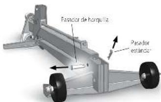
natural_image
Mechanical assembly diagram showing a rotating component with directional arrows (no text or symbols)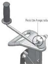
natural_image
Top-down schematic of a vehicle suspension system with two wheels and support structures (no text or labels)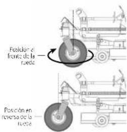
natural_image
Diagram of a car with wheels and a lift, showing mechanical components and motion arrows (no text or symbols)30
PASO 9
natural_image
Technical diagram of an aircraft landing gear assembly with no visible text or symbolsESPAÑOL
ESPAÑOL
PASO 11
natural_image
Technical line drawing of a mechanical vehicle with mounting bracket and support structure (no text or symbols)PASO 15
natural_image
Mechanical assembly diagram showing a lever mechanism with directional arrows (no text or labels)PASO 20
natural_image
Illustration of a person performing a leg lift exercise with a vertical post and motion arrows (no text or symbols)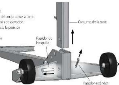
Definitions: Safety Alert Symbols and Words
natural_image
Collection of mechanical components including a vertical pole, clamps, and attached parts (no text or symbols visible)ÉTAPE 2
natural_image
Mechanical support system with articulated arms and wheels (no text or symbols visible)
natural_image
Mechanical assembly diagram showing a lever mechanism with rotational motion arrows (no text or symbols)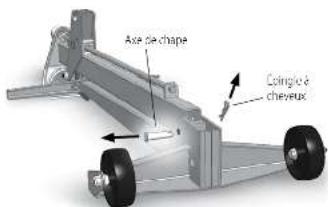
natural_image
Technical diagram of a vehicle suspension system with two wheels and support structures (no text or labels)ÉTAPE 7
natural_image
Diagram of a tractor with wheels and a lift, showing mechanical components and directional arrows (no text or symbols)48
ÉTAPE 9
49
FRANÇAIS
ÉTAPE 11
natural_image
Diagram of a grassing machine with directional arrows indicating movement or force (no text or symbols present)ÉTAPE 15
natural_image
Mechanical assembly diagram showing a lever mechanism with directional arrows (no text or labels)ÉTAPE 20
natural_image
Diagram of a mechanical device with rotating arm and base, showing motion direction (no text or symbols)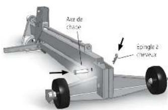
is a registered trademark of Stanley Black & Decker, Inc., used under license.
Product manufactured by:
MoJack Distributors, LLC
3535 N. Rock Road, Wichita, KS 67226

- Definitions: Safety Alert Symbols and Words
- Warning and Safety Instructions
- WARNING: To reduce the risk of personal injury:
- Assembly Instructions
- STEP 1
- STEP 2
- STEP 3
- STEP 4
- STEP 5
- STEP 6
- STEP 7
- STEP 8
- Operating Instructions
- Preparing for Use (Steps 1 - 7)
- Using the Lift (Steps 8 - 15)
- STEP 9
- STEP 10
- STEP 11
- STEP 12
- STEP 13
- STEP 14
- STEP 15
- Preparing for Storage (Steps 16 - 20)
- STEP 16
- STEP 17
- STEP 18
- STEP 19
- STEP 20
- Maintenance Schedule
- Register Online
- Two Year Limited Warranty
- DAY MONEY BACK GUARANTEE
- PASO 2
- PASO 9
- PASO 11
- PASO 15
- PASO 20
- ÉTAPE 2
- ÉTAPE 7
- ÉTAPE 9
- ÉTAPE 11
- ÉTAPE 15
- ÉTAPE 20
Brand : Craftsman
Model : CMKGAAV45099000
Category : Lawn mower