
MILENCO AERO3 - Rearview Mirror DOMETIC - Free user manual and instructions
Find the device manual for free MILENCO AERO3 DOMETIC in PDF.
| Product type | Towing mirror (Aero Wide) |
| Brand | Dometic |
| Model | MILENCO AERO3 (DM-1899 / DM-2899) |
| Material | Reinforced plastic and metal |
| Package contents | 4 clamps, 2 mirrors, 2 sliding arms, 1 storage cover |
| Number of mirrors | 2 (driver and passenger side) |
| Mounting type | On existing vehicle mirror, above or below |
| Adjustment | Mirror orientation, height and angle of sliding arm (4 positions) |
| Compatibility | Most vehicles with a gap between mirror and housing |
| Tools required | Phillips screwdriver No. 2 |
| Main functions | Improves lateral visibility when towing |
| Safety | Do not use automatic car wash with mirrors attached |
| Maintenance | Clean with soft cloth, store in provided cover |
| Spare parts available | Mirror (DM-1984), clamp (DM-1960), Aero pad (DM-1953) |
| Installation conditions | Follow local and national codes (USA/CANADA: N.U. 46.02) |
| Marking | Compliant with directive 2003/97/EC |
Frequently Asked Questions - MILENCO AERO3 DOMETIC
User questions about MILENCO AERO3 DOMETIC
0 question about this device. Answer the ones you know or ask your own.
Ask a new question about this device
Download the instructions for your Rearview Mirror in PDF format for free! Find your manual MILENCO AERO3 - DOMETIC and take your electronic device back in hand. On this page are published all the documents necessary for the use of your device. MILENCO AERO3 by DOMETIC.
USER MANUAL MILENCO AERO3 DOMETIC
RECORD THIS INFORMATION FOR FUTURE REFERENCE:
Model Number
Serial Number
Date Purchased
Retailer / Qualified Installer
INSTALLATION
INSTRUCTIONS
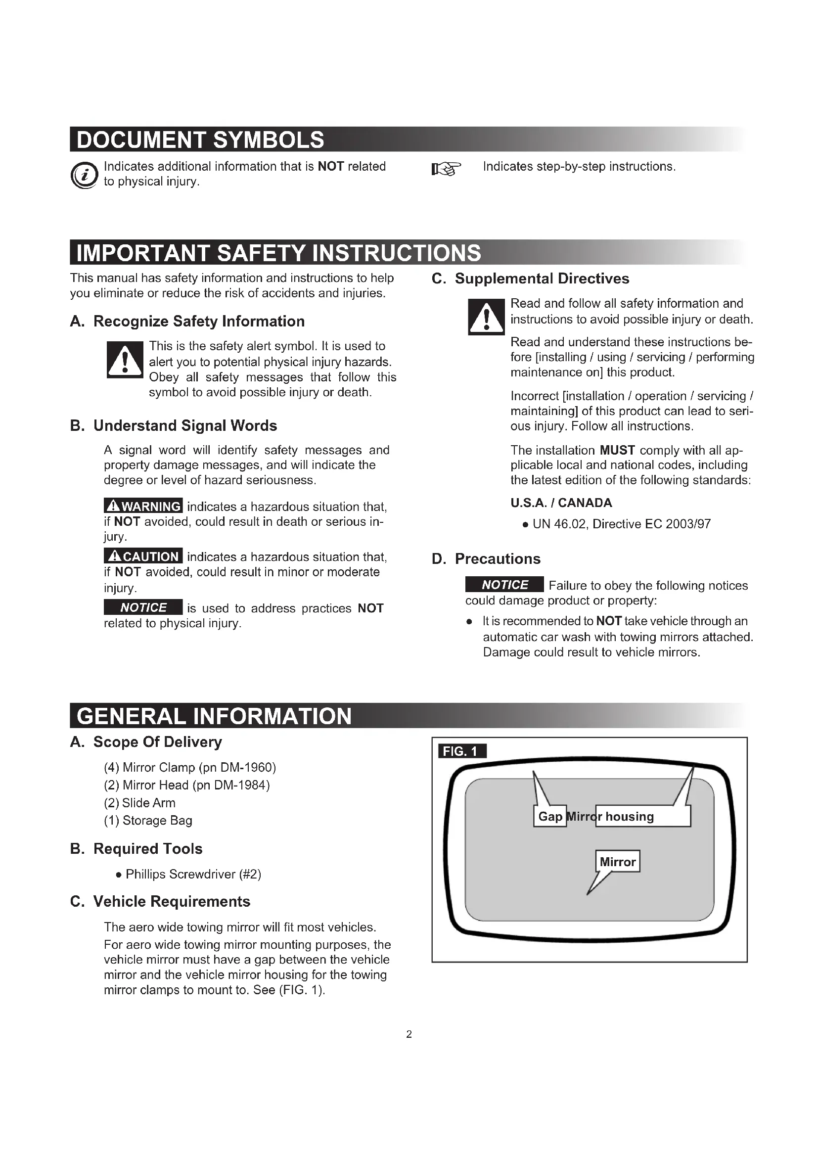
MILENCO AERO WIDE TOWING MIRROR
DM-1899
DM-2899
natural_image
Close-up of a black oval-shaped eyeglass with attached metal bracket (no text or symbols visible)
Read these instructions carefully. These instructions MUST stay with this product.
DOCUMENT SYMBOLS

Indicates additional information that is NOT related to physical injury.

Indicates step-by-step instructions.
IMPORTANT SAFETY INSTRUCTIONS
This manual has safety information and instructions to help you eliminate or reduce the risk of accidents and injuries.
A. Recognize Safety Information

This is the safety alert symbol. It is used to alert you to potential physical injury hazards. Obey all safety messages that follow this symbol to avoid possible injury or death.
B. Understand Signal Words
A signal word will identify safety messages and property damage messages, and will indicate the degree or level of hazard seriousness.
WARNING indicates a hazardous situation that, if NOT avoided, could result in death or serious injury.
⚠ CAUTION indicates a hazardous situation that, if NOT avoided, could result in minor or moderate injury.
NOTICE is used to address practices NOT related to physical injury.
C. Supplemental Directives

Read and follow all safety information and instructions to avoid possible injury or death.
Read and understand these instructions before [installing / using / servicing / performing maintenance on] this product.
Incorrect [installation / operation / servicing / maintaining] of this product can lead to serious injury. Follow all instructions.
The installation MUST comply with all applicable local and national codes, including the latest edition of the following standards:
U.S.A. / CANADA
• UN 46.02, Directive EC 2003/97
D. Precautions
NOTICE Failure to obey the following notices could damage product or property:
- It is recommended to NOT take vehicle through an automatic car wash with towing mirrors attached. Damage could result to vehicle mirrors.
GENERAL INFORMATION
A. Scope Of Delivery
(4) Mirror Clamp (pn DM-1960)
(2) Mirror Head (pn DM-1984)
(2) Slide Arm
(1) Storage Bag
B. Required Tools
• Phillips Screwdriver (#2)
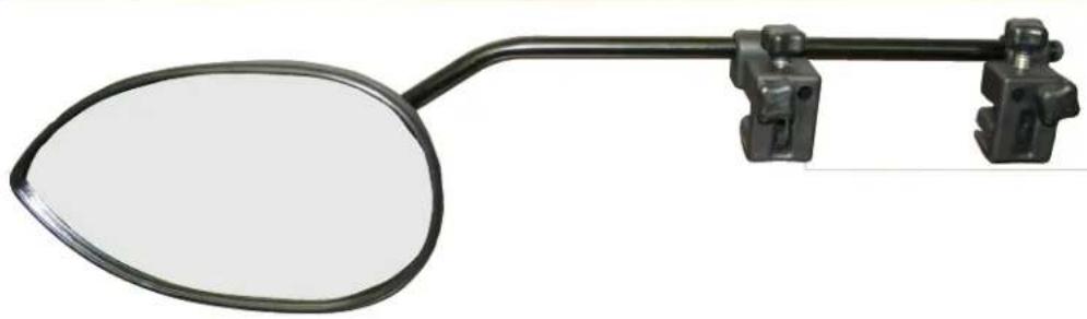
C. Vehicle Requirements
The aero wide towing mirror will fit most vehicles. For aero wide towing mirror mounting purposes, the vehicle mirror must have a gap between the vehicle mirror and the vehicle mirror housing for the towing mirror clamps to mount to. See (FIG. 1).
INSTALLATION
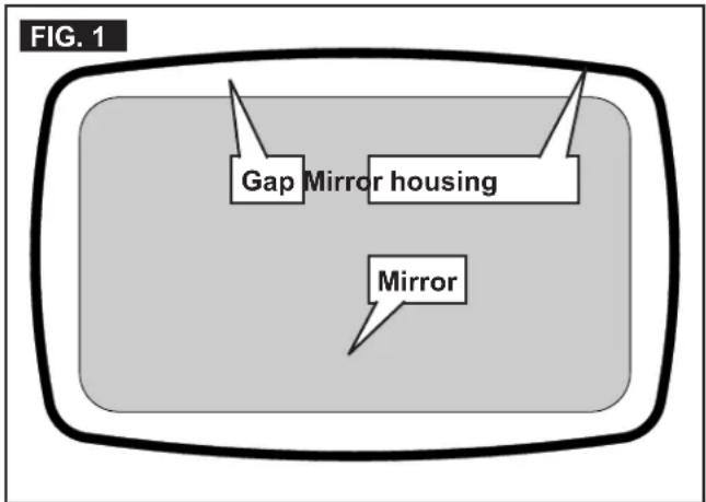
A. Mirror Assembly

- Assemble mirror head to arm.
a. Using a #2 Phillips screwdriver, remove truss head screw (4 mm x 28 mm) from mirror head ball socket. See (FIG. 2).
b. Slide short end of arm into hole in mirror head ball socket, aligning cross hole in arm with screw hole in mirror head ball socket. Select desired arm position (right hand, left hand, etc.). See (FIG. 3).
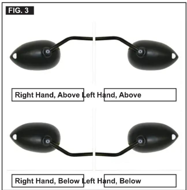

NOTE: To change from right hand to left hand, and left hand to right hand, rotate arm in ball socket 180°.
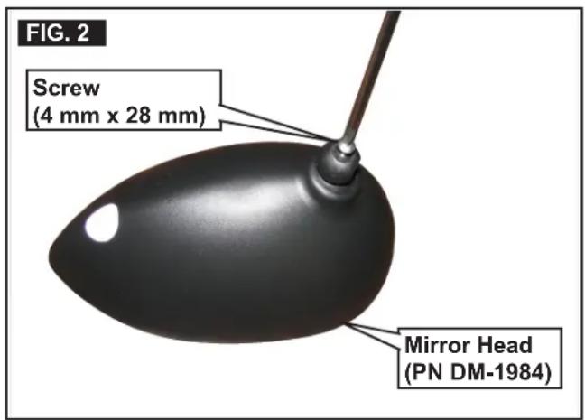
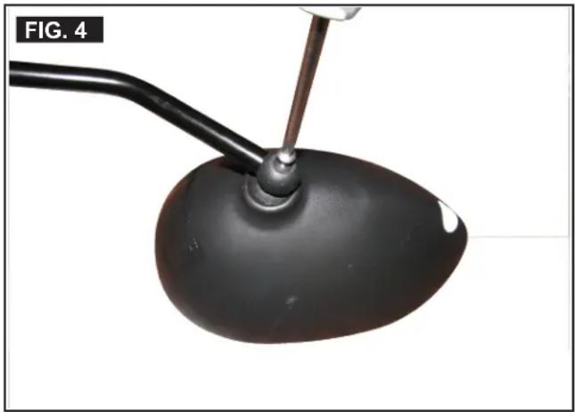
c. Assemble screw to mirror head ball socket and hand tighten with a #2 Phillips screw-driver, securing mirror head to arm. See (FIG. 4).
natural_image
Close-up of a black, oval-shaped object with a metal rod inserted, labeled 'FIG. 4' in the corner (no other text or symbols)- Repeat steps (a) through (c) for other mirror.
B. Mirror Installation
The aero wide towing mirror can be mounted above or below the vehicle mirror, whichever works best for your situation. On certain vehicles, it may only fit above or below the vehicle mirror. See (FIG. 3).

- Loosen thumb screws ("2" on thumb screw), and remove mirror clamps from slide arm. See (FIG. 5).
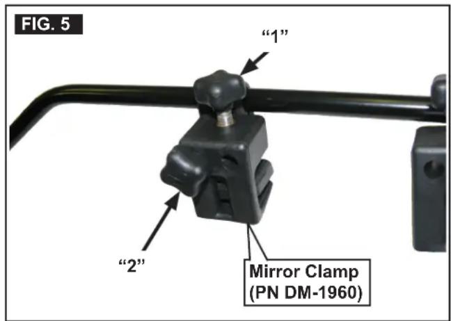
- Loosen thumb screws ("1" on thumb screw). See (FIG. 5).
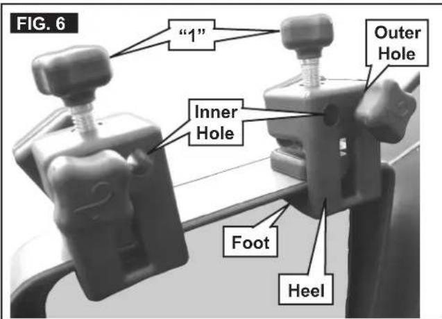
- Assemble (2) mirror clamps to vehicle mirror, sliding "foot" of clamps between vehicle mirror and vehicle mirror housing. See (FIG. 6).

Slide clamps in as far as possible for maximum clamp contact.
INSTALLATION
-
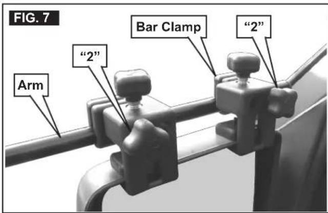
Position mirror clamps approximately 2" to 4" apart with the bar clamps in the outer hole position. See (FIG. 6).
-
Tighten thumb screws ("1" on thumb screw) by hand, pressing heel of clamp against vehicle mirror on both clamps. See (FIG. 6).
NOTICE Do NOT use tools to tighten thumb screws. Doing so could damage vehicle mirror housing.
NOTICE Failure to obey the following instructions, by fitting the mirror with the clamps on the arm, may result in the loss of the mirror.
- Select desired arm position altitude and angle and slide arm into clamps. The (2) bar clamps can be positioned up or down, therefore, the arm can be mounted in one of four positions, high, low, and for vehicles with tapered mirrors, it is possible to level the arm by positioning one bar clamp down and the other bar clamp up. Tighten thumb screws ("2" on thumb screw), securing mirror clamp position on slide arm. See (FIG. 7).
-
Repeat steps (1) through (6) for other mirror.
-
To make mirror adjustments, it is recommended that one person sit in the driver's seat giving mirror adjustment directions while another person makes the mirror adjustments.

NOTE: Rotate mirror so "point" is away from vehicle, with reflector outward.
C. Removal

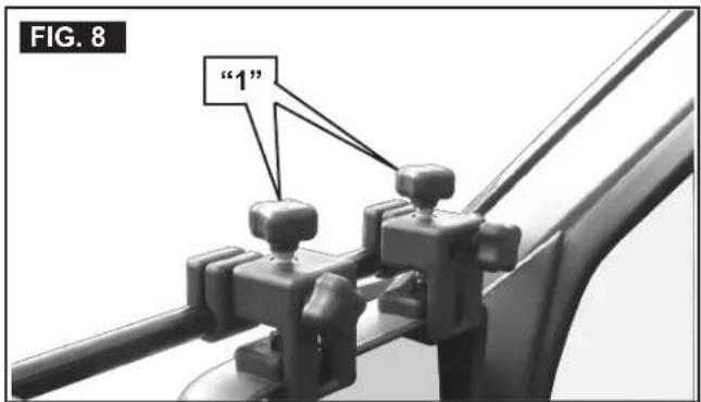
- To remove towing mirrors from vehicle, loosen thumb screws ("1" on thumb screw), allowing removal. See (FIG. 8).
- Place mirror assemblies in storage bag.
D. DM-1953 Aero Pad Replacement

-
Loosen thumb screws ("1" on thumb screw) and remove mirror and components from vehicle. See (FIG. 8).
-
Unthread thumb screws ("1" on thumb screw) sufficiently to allow removal of DM-1953 aero pad.
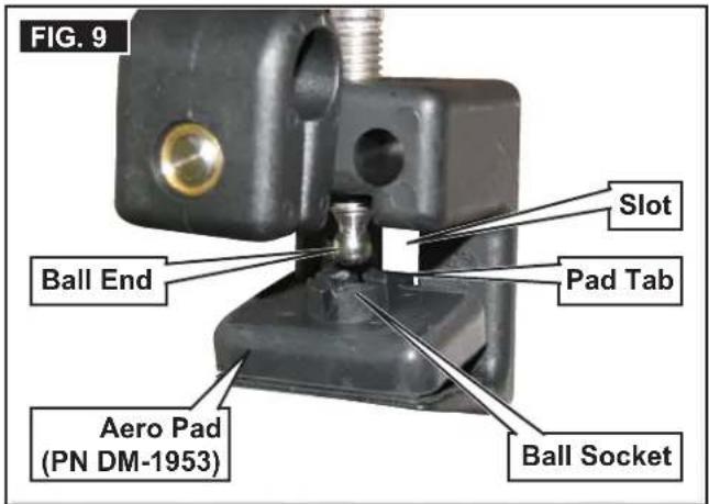
-
Pull pad from ball end of thumb screw. See (FIG. 9).
-
Assemble replacement pad to clamp, aligning tab of pad with slot in clamp housing and aligning ball socket on top of pad with ball end of thumb screw. See (FIG. 9).
-
Press pad onto thumb screw.

NOTE: It may be helpful to tighten thumb screw ("1" on thumb screw) until ball end "snaps" into ball socket of pad.
NOTER CETTE INFORMATION POUR S'Y REPORTER ULTÉRIEUREMENT :
N° de modèle
N° de série
Date d'achat
natural_image
Close-up of a black oval-shaped eyeshadow with attached metal clips (no text or symbols visible)
natural_image
Close-up of a black oval-shaped object with a metal rod inserted, labeled 'FIG. 4' in the top-left corner (no other text or symbols)natural_image
Close-up of a black oval-shaped eyeshadow with attached metal clips (no text or symbols visible)
natural_image
Close-up of a black, oval-shaped object with a metal rod inserted, labeled 'FIG. 4' in the corner (no other text or symbols)- INSTALLATION
- INSTRUCTIONS
- MILENCO AERO WIDE TOWING MIRROR
- DOCUMENT SYMBOLS
- IMPORTANT SAFETY INSTRUCTIONS
- Recognize Safety Information
- Understand Signal Words
- Supplemental Directives
- U.S.A. / CANADA
- Precautions
- GENERAL INFORMATION
- Scope Of Delivery
- Required Tools
- Vehicle Requirements
- Mirror Assembly
- Mirror Installation
- Removal
- DM-1953 Aero Pad Replacement
Brand : DOMETIC
Model : MILENCO AERO3
Category : Rearview Mirror