JVC3300JSA - Range hood GE - Free user manual and instructions
Find the device manual for free JVC3300JSA GE in PDF.



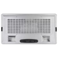
| Brand | GE |
| Model | JVC3300JSA |
| Product Type | Built-in and convertible range hood |
| Width | 30 inches (standard, skirt models available: 30 and 36 inches) |
| Depth | 19-1/2 inches |
| Installation Height | 24 to 36 inches above cooking surface (minimum 24 in, recommended maximum 36 in) |
| Minimum Interior Cabinet Height | 16 inches |
| Weight (approx) | 13.6 kg (30 lb) |
| Power Supply | 120 V, 60 Hz, 15 or 20 A |
| Duct Type | Metal only, 6 inch diameter (round) |
| Fan Speeds | 3 speeds: low (1), medium (2), high (3) |
| Heat Sensor | Yes, thermostat activates or speeds up fan in case of excessive heat |
| Lighting | 2 candelabra bulbs max 40 W (E12, type B or T8) |
| Grease Filter | Metal, washable (part WB02X26416) |
| Recirculation Operation | Possible with JXN30 kit (sold separately) |
| Surface Material | Enamel paint |
| Cleaning | Soft cloth, warm water, mild detergent; no abrasive pads |
| Warranty | 1 year (parts and labor) |
| Safety | Grounding required; fan stops in case of overheating; use metal ducts only |
| Replacement Parts | Skirts JXL30 (30 in) and JXL36 (36 in), recirculation kit JXN30, grease filter WB02X26416 |
| Installation | Electrical connection via plug; vertical or horizontal duct; requires 2 people |
Frequently Asked Questions - JVC3300JSA GE
User questions about JVC3300JSA GE
0 question about this device. Answer the ones you know or ask your own.
Ask a new question about this device
Download the instructions for your Range hood in PDF format for free! Find your manual JVC3300JSA - GE and take your electronic device back in hand. On this page are published all the documents necessary for the use of your device. JVC3300JSA by GE.
USER MANUAL JVC3300JSA GE
Installation Instructions
Before You Begin 9
Installation Preparation .....10-13
Installing the Hood .....14, 15
Finalize Installation 15
Troubleshooting Tips ..... 1 6
Owner's Manual and Installation Instructions
JVC3300 Hood
For a Spanish version of this manual, visit our Website at GEAppliances.com.
For a French version of this manual, visit our Website at GEAppliances.com.
Write the model and serial numbers here:
Model # ____
Serial # ____
You can find them on a label on the inside of the hood.
IMPORTANT SAFETY INFORMATION. READ ALL INSTRUCTIONS BEFORE USING.

This is the safety alert symbol. This symbol alerts you to potential hazards that can kill or hurt you and others.
All safety messages will follow the safety alert symbol and the word "DANGER", "WARNING", or "CAUTION". These words are defined as:

DANGER
Indicates a hazardous situation which, if not avoided, will result in death or serious injury.

WARNING
Indicates a hazardous situation which, if not avoided, could result in death or serious injury.

CAUTION
Indicates a hazardous situation which, if not avoided, could result in minor or moderate injury.
SAFETY PRECAUTIONS
WARNING
TO REDUCE THE RISK OF FIRE, ELECTRIC SHOCK OR INJURY TO PERSONS, OBSERVE THE FOLLOWING:
A. Use this unit only in the manner intended by the manufacturer. If you have questions, contact the manufacturer.
B. Before servicing or cleaning unit, switch power off at service panel and lock the service disconnecting means to prevent power from being switched on accidentally. When the service disconnecting means cannot be locked, securely fasten a prominent warning device, such as a tag, to the service panel.
C. Do not use this unit with any solid-state speed control device.
D. This unit must be grounded.

CAUTION
FOR GENERAL VENTILATING USE ONLY. DO NOT USE TO EXHAUST HAZARDOUS OR EXPLOSIVE MATERIALS AND VAPORS.

CAUTION
TO REDUCE RISK OF FIRE AND TO PROPERLY EXHAUST AIR, BE SURE TO DUCT AIR OUTSIDE. DO NOT VENT EXHAUST AIR INTO SPACES WITHIN WALLS OR CEILINGS OR INTO ATTICS, CRAWL SPACES OR GARAGES.
WARNING
TO REDUCE THE RISK OF INJURY TO PERSONS IN THE EVENT OF A RANGE TOP GREASE FIRE, OBSERVE THE FOLLOWING*:
A. SMOTHER FLAMES with a close-fitting lid, cookie sheet or metal tray, then turn off the burner. BE CAREFUL TO PREVENT BURNS. If the flames do not go out immediately, EVACUATE AND CALL THE FIRE DEPARTMENT.
B. NEVER PICK UP A FLAMING PAN—You may be burned.
C. DO NOT USE WATER, including wet dishcloths or towels—a violent steam explosion will result.
D. Use an extinguisher ONLY if:
1. You know you have a Class ABC extinguisher, and you already know how to operate it.
2. The fire is small and contained in the area where it started.
3. The fire department is being called.
4. You can fight the fire with your back to an exit.
* Based on "Kitchen Fire Safety" published by NFPA.
SAFETY PRECAUTIONS (Cont.)
WARNING
TO REDUCE THE RISK OF A P GREASE FIRE:
A. Never leave surface units unattended at high settings. Boilovers cause smoking and greasy spillovers may ignite. Heat oils slowly on low or medium settings.
B. Always turn hood ON when cooking on high heat or when flambéing food (i.e. Crepes Suzette, Cherries Jubilee, Peppercorn Beef Flambé).
C. Clean ventilating fans frequently. Grease should not be allowed to accumulate on fan or filter.
D. Use proper pan size. Always use cookware appropriate for the size of the surface element.
WARNING
TO REDUCE THE RISK OF FIRE, SHOCK OR INJURY TO PERSONS, THE FOLLOWING:
A. Installation work and electrical wiring must be done by qualified person(s) in accordance with all applicable codes and standards, including fire-rated construction.
B. Sufficient air is needed for proper combustion and exhausting of gases through the flue (chimney) of fuel burning equipment to prevent back drafting. Follow the heating equipment manufacturer's guidelines and safety standards such as those published by the National Fire Protection Association (NFPA), the American Society for Heating, Refrigeration and Air Conditioning Engineers (ASHRAE) and the local code authorities.
C. When cutting or drilling into wall or ceiling, do not damage electrical wiring and other hidden utilities.
D. Ducted fans must always be vented to the outdoors.
E. When applicable, install any makeup (replacement) air system in accordance with local building code requirements. Visit GEAppliances.com for available makeup air solutions.
F. Turn off breaker to adjacent rooms while working.
WARNING
TO REDUCE THE RISK OF FIRE, METAL DUCTWORK.
- Do not attempt to repair or replace any part of your hood unless it is specifically recommended in this manual. All other servicing should be referred to a qualified technician.
Thank You! ... for your purchase of a GE Brand appliance.
Register Your Appliance: Register your new appliance on-line at your convenience!
www.geappliances.com/service_and_support/register/
Timely product registration will allow for enhanced communication and prompt service under the terms of your warranty, should the need arise. You may also mail in the pre-printed registration card included in the packing material.
GE Warranty
GEAppliances.com
All warranty service is provided by our Factory Service Centers, or an authorized Customer Care® technician. To schedule service, on-line, visit us at www.geappliances.com/service_and_support/, or call 800.GE.CARES (800.432.2737). Please have serial number and model number available when calling for service.
Servicing your appliance may require the use of the onboard data port for diagnostics. This gives a GE factory service technician the ability to quickly diagnose any issues with your appliance and helps GE improve its products by providing GE with information on your appliance. If you do not want your appliance data to be sent to GE, please advise your technician not to submit the data to GE at the time of service.
For the period of one year from the date of the original purchase, GE will provide any part of the hood insert which fails due to a defect in materials or workmanship. During this limited one-year warranty, GE will also provide, free of charge, all labor and in-home service to replace the defective part.
What GE will not cover:
■ Service trips to your home to teach you how to use the product.
■ Improper installation, delivery or maintenance.
■ Failure of the product if it is abused, misused, modified or used for other than the intended purpose or used commercially.
■ Replacement of house fuses or resetting of circuit breakers.
■ Damage to the product caused by accident, fire, floods or acts of God.
■ Damage to finish, such as surface rust, tarnish, or small blemishes not reported within 48 hours of delivery.
■ Incidental or consequential damage caused by possible defects with this appliance.
■ Damage caused after delivery.
■ Product not accessible to provide required service.
■ Service to repair or replace light bulbs, except for LED lamps.
EXCLUSION OF IMPLIED WARRANTIES
Your sole and exclusive remedy is product repair as provided in this Limited Warranty. Any implied warranties, including the implied warranties of merchantability or fitness for a particular purpose, are limited to one year or the shortest period allowed by law.
This warranty is extended to the original purchaser and any succeeding owner for products purchased for home use within the USA. If the product is located in an area where service by a GE Authorized Servicer is not available, you may be responsible for a trip charge or you may be required to bring the product to an Authorized GE Service location for service. In Alaska, the warranty excludes the cost of shipping or service calls to your home.
Some states do not allow the exclusion or limitation of incidental or consequential damages. This warranty gives you specific legal rights, and you may also have other rights which vary from state to state. To know what your legal rights are, consult your local or state consumer affairs office or your state's Attorney General.
Warrantor: General Electric Company. Louisville, KY 40225
Extended Warranties: Purchase a GE extended warranty and learn about special discounts that are available while your warranty is still in effect. You can purchase it on-line anytime
www.geappliances.com/service_and_support/shop-for-extended-service-plans.htm
or call 800.626.2224 during normal business hours. GE Consumer Home Services will still be there after your warranty expires.
Have a question or need assistance with your appliance?
Try the GE Appliances Website (www.geappliances.com/service_and_support/) 24 hours a day, any day of the year! For greater convenience and faster service, you can now download Owner's Manuals, order parts or even schedule service on-line.
Schedule Service: Expert GE repair service is only one step away from your door. Get on-line and schedule your service at www.geappliances.com/service_and_support/ Or call 800.GE.CARES (800.432.2737) during normal business hours.
Parts and Accessories: Individuals qualified to service their own appliances can have parts or accessories sent directly to their homes (VISA, MasterCard and Discover cards are accepted). Order on-line today, 24 hours every day or by phone at 800.626.2002 during normal business hours.
Instructions contained in this manual cover procedures to be performed by any user. Other servicing generally should be referred to qualified service personnel. Caution must be exercised, since improper servicing may cause unsafe operation.
Real Life Design Studio: GE supports the Universal Design concept of products, services and environments that can be used by people of all ages, sizes and capabilities. We recognize the need to design for a wide range of physical and mental abilities and impairments. For details of GE's Universal Design applications, including kitchen design ideas for people with disabilities, check out our Website today. For the hearing impaired, please call 800.TDD.GEAC (800.833.4322).
Contact Us: If you are not satisfied with the service you receive from GE, contact us on our Website with all the details including your phone number, or write to:
General Manager, Customer Relations GE Appliances, Appliance Park Louisville, KY 40225
Accessories
Looking For Something More?
GE offers a variety of accessories to improve your cooking and maintenance experiences!
To place an order visit us online at:
www.GEApplianceParts.com or call 800.626.2002
The following products and more are available:
Parts
| Liners 30":JXL30 36":JXL36 | |
| Recirculation Kit JXN30 | |
| Grease Filter WB02X26416 |
How to Remove Protective Shipping Film and Packaging Tape
Carefully grasp a corner of the protective shipping film with your fingers and slowly peel it from the appliance surface. Do not use any sharp items to remove the film. Remove all of the film before using the appliance for the first time.
To assure no damage is done to the finish of the product, the safest way to remove the adhesive from packaging tape on new appliances is an application of a household liquid dishwashing detergent. Apply with a soft cloth and allow to soak.
NOTE: The adhesive must be removed from all parts.
Controls
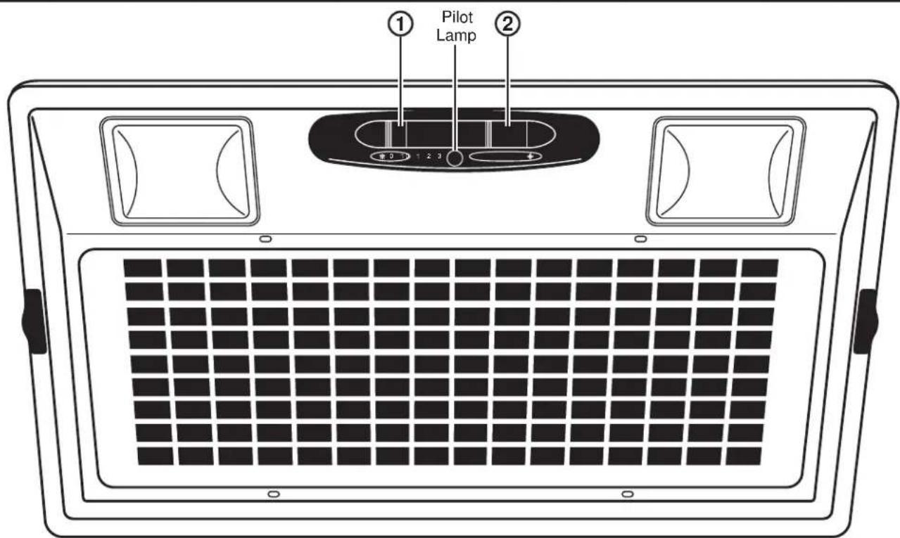
- Light Switch: 0 is OFF. Move switch to 1 for ON.
- Blower Switch: 0 is OFF. Move switch to 1 for LOW speed, 2 for MEDIUM speed, and 3 for HIGH speed. The pilot lamp illuminates when the blower switch is set to 1, 2, or 3.
Heat Sensor
Your hood is equipped with a HEAT SENSOR thermostat. This thermostat is a device that will turn on or speed up the blower if it senses excessive heat above the cooking surface.
- If blower is OFF - it turns blower ON to HIGH speed.
- If blower is ON at a lower speed setting - it turns blower up to HIGH speed.
When the temperature level drops to normal, the blower will return to its original setting.
Filters
Be sure the circuit breaker is off and all surfaces are cool before cleaning or servicing any part of the vent hood.
Metal Grease Filter
The metal filters trap grease during cooking.
The filter must ALWAYS be in place when the hood is in use. The grease filter is dishwasher-safe and should be cleaned every 6 months, or as needed.
To remove:
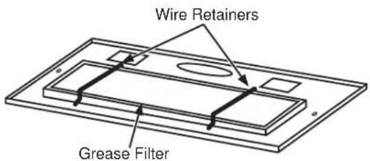
Remove the access panel by sliding the two side latches. Remove the wire retainers and then remove the grease filter.
To replace:
Align the grease filter and install the wire retainers. Replace the access panel.
To clean, swish the filter in hot soapy water and rinse in clean water or wash it in the dishwasher. Do not use abrasive cleansers.
NOTE: Some discoloration may occur in the dishwasher.
For Recirculation Installation Only
Charcoal Filter (Not Included)
When the hood is installed with the recirculation kit JXN30, there is a charcoal filter on top of the grease filter. To remove and reinstall the charcoal filter, follow the steps for the grease filter.
NOTE: DO NOT rinse, or put charcoal filter in an automatic dishwasher.
The charcoal filter cannot be cleaned. It must be replaced. It is recommended that the charcoal filter be replaced every 6 months or if it is noticeably dirty or discolored.
Order Charcoal Filter WB28X10120
To inquire about purchasing replacement charcoal filters or to find the location of a dealer nearest you, please call our toll-free number:
National Parts Center 800.626.2002
Surfaces
Painted Surfaces
Do not use a steel wool pads or other abrasive cleaners; they will scratch the surface.
Clean grease-laden surfaces of the hood frequently. To clean the hood surface, use a hot, damp cloth with a mild detergent suitable for painted surfaces. About one tablespoon of ammonia may be added to the water. Use a clean, hot, damp cloth to remove soap. Dry with a dry, clean cloth.
NOTE: When cleaning, take care not to come in contact with filters and other non-enameled surfaces.
CAUTION
When cleaning the hood surfaces, be certain that you do not touch the light with moist hands or cloth. A warm or hot light may break if touched with a moist surface. Always let the light cool completely before cleaning around it.
Light Bulbs
CAUTION
Allow lights to cool before
touching.
To change the light bulbs:
- Before attempting to replace the lights, make sure that the light switch is turned off.
- Remove the access panel (slide the two side latches).
- Replace with candelabra base light bulbs (MAX 40W, 120V, E12, Type B or Type T8 Bulb).
CAUTION
BULB MAY BE HOT!
- Reinstall the access panel.
Installation Instructions
Custom Hood Insert
JVC3300 Hood
? "If you have questions, call 800.GE.CARES (800.432.2737) or visit our website at: GEAppliances.com"
BEFORE YOU BEGIN
Read these instructions completely and carefully.
- IMPORTANT — Save these instructions for local inspector's use.
- IMPORTANT — Observe all governing codes and ordinances.
- Note to Installer – Be sure to leave these instructions with the Consumer.
- Note to Consumer – Keep these instructions for future reference.
- Skill level – Installation of this vent hood requires basic mechanical and electrical skills.
- Proper installation is the responsibility of the installer.
- Product failure due to improper installation is not covered under the Warranty.

CAUTION
TWO PEOPLE ARE
RECOMMENDED FOR PROPER INSTALLATION.
FOR YOUR SAFETY:

WARNING
Before beginning the installation, switch power off at service panel and lock the service disconnecting means to prevent power from being switched on accidentally. When the service disconnecting means cannot be locked, securely fasten a prominent warning device, such as a tag, to the service panel.
WARNING
TO REDUCE THE RISK OF
FIRE, ELECTRIC SHOCK OR INJURY TO PERSONS, OBSERVE THE FOLLOWING:
A. Installation work and electrical wiring must be done by qualified person(s) in accordance with all applicable codes and standards, including fire-rated construction.
B. Sufficient air is needed for proper combustion and exhausting of gases through the flue (chimney) of fuel burning equipment to prevent back drafting. Follow the heating equipment manufacturer's guidelines and safety standards such as those published by the National Fire Protection Association (NFPA), the American Society for Heating, Refrigeration and Air Conditioning Engineers (ASHRAE) and the local code authorities.
C. When cutting or drilling into wall or ceiling, do not damage electrical wiring and other hidden utilities.
D. Ducted fans must always be vented to the outdoors.
E. Turn off breaker to adjacent rooms while working.
WARNING
TO REDUCE THE RISK OF
FIRE, USE ONLY METAL DUCT WORK.
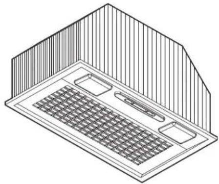
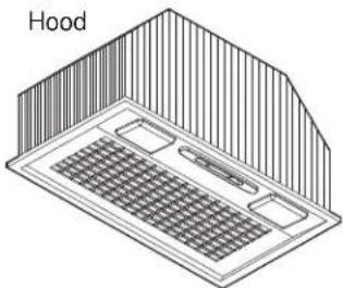
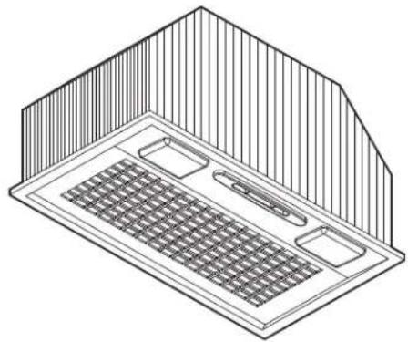
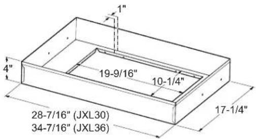
PRODUCT DIMENSIONS
natural_image
Isometric line drawing of a ceiling-mounted air vent with grating and ventilation slots (no text or symbols)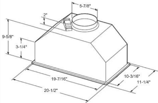
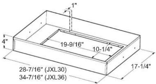
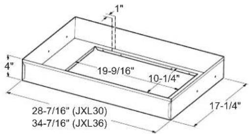
Liners (Optional)
INSTALLATION CLEARANCES
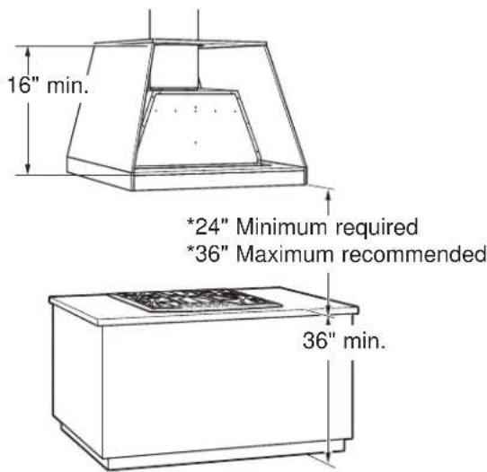
This vent hood and liner assembly must be installed 24" required minimum and 36" recommended maximum above the cooking surface.
- Always refer to the cooktop or range installation instructions for product-specific clearances.
NOTE: Installation height should be measured from the cooking surface to the bottom edge of the metal hood liner or cabinet surface.
NOTE: UL requires any combustible surface to be a minimum of 30" above the cooking surface.
- The custom cabinet internal height must be 16" minimum.
- This hood can be vented to the outdoors, or it can be installed for recirculating operation. For recirculating operation, refer to Recirculating Installation Planning.
- This hood may be mounted onto a cabinet or installed over an island.
ADVANCE PLANNING
Duct Install Planning
- This hood is designed to be vented vertically through the ceiling. Use a 6" round duct. Use locally supplied elbows to vent horizontally through the rear wall.
- Use metal ductwork only.
• Determine the exact location of the vent hood. -
Plan the route for venting exhaust to the outdoors.
To maximize the ventilation performance of the vent system: -
Minimize the duct run length and number of transitions and elbows.
- Maintain a constant duct size.
- Seal all joints with duct tape to prevent any leaks.
- Do not use any type of flexible ducting.
- Install a wall cap or roof cap with damper at the exterior opening. Purchase the wall or roof cap and any transition and length of duct needed in advance.
- When applicable, install any makeup (replacement) air system in accordance with local building code requirements. Visit GEAppliances.com for available makeup air solutions.
Wall and Ceiling Framing for Adequate Support
This vent hood is heavy and the cabinet structure needs to support the weight of the loaded insert sleeve. Adequate structural support must be provided in all types of installations.
- Installation will be easier if the vent hood is installed before the cooktop is installed.
Custom Cabinet Frame Planning
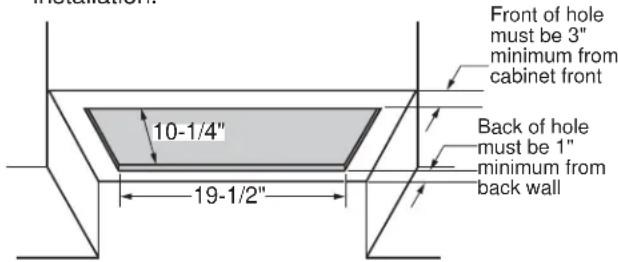
- The custom canopy or cabinet should have a rectangular hole to accommodate the custom hood insert by itself, or with the liner. This hole is the same size for both a wall installation and an island installation.
Metal Liners
- Metal liners (30" width JXL30 and 36" width JXL36) are optional but are recommended for installation heights below 30" for cabinetry protection. You can construct a custom metal (or non-combustible) liner when a larger liner is needed.
Recirculation Install Planning
A recirculation duct kit JXN30 is available for recirculation installation.
Power Supply Planning
The location of the power supply connection is called out in the Wall Installation and Island Installation sections on page 13.
POWER SUPPLY
IMPORTANT – (Please read carefully)
WARNING
FOR PERSONAL SAFETY, THIS APPLIANCE MUST BE PROPERLY GROUNDED.
In the event of an electrical short circuit, grounding reduces the risk of electric shock by providing an escape wire for the electric current. This appliance is equipped with a cord having a grounding wire with a grounding plug. The plug must be plugged into an outlet that is properly installed and grounded.
Remove house fuse or open circuit breaker before beginning installation.
Do not use an extension cord or adapter plug with this appliance. If the power supply cord is too short, have a qualified electrician install an outlet near the appliance. Do not operate any fan with a damaged cord or plug. Discard fan or return to an authorized service facility for examination and/or repair. Follow National Electrical Codes or prevailing local codes and ordinances.
Electrical supply
These vent hoods must be supplied with 120V, 60Hz, and connected to an individual, properly grounded branch circuit, and protected by a 15 or 20 amp circuit breaker or time delay fuse.
- Wiring must be 2 wire with ground.
- If the electrical supply does not meet the above requirements, call a licensed electrician before proceeding.
- Route house wiring as close to the installation location as possible in the ceiling or wall.
- Connect the wiring to the house wiring in accordance with local codes.
WARNING
The improper connection of the equipment-grounding conductor can result in a risk of electric shock. Consult a qualified electrician if the grounding instructions are not completely understood, or if doubt exists as to whether the appliance is properly grounded.
TOOLS AND MATERIALS REQUIRED
(NOT SUPPLIED)
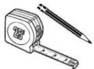
Pencil and tape measure

Aluminized
duct tape
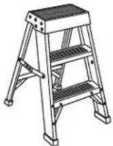
Step ladder
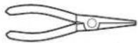
Needle-nose pliers
Silicone
natural_image
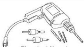
Line drawing of a drill bit with multiple drill bits and a power plug (no text or symbols)Electric drill and appropriate bits
Safety glasses
6" ducting and caps as needed

Spirit level
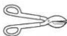
Tin snips
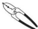
Wire cutter/ stripper
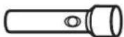
Flashlight

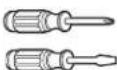
Phillips and flat-blade screwdrivers
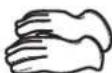
Gloves
PARTS PROVIDED
Locate the parts packed with the hood.
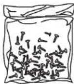
Hardware bag
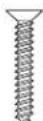
Phillips head
wood screws
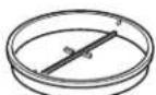
Damper assembly
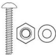
Phillips head machine screws, nuts and washers
natural_image
Isometric line drawing of a 3D hood with grid pattern and ventilation slots (no text or symbols)PLAN THE INSTALLATION
CAUTION
To reduce risk of fire and tohaust air, be sure to duct the properly exhaust air, be sure to duct the air outside – Do not vent exhaust air into spaces within walls or ceilings or into attics, crawl spaces, or garages.
WARNING
PERSONAL INJURY HAZARD
It is recommended that 2 people are used to install the range hood. Failure to properly lift rangehood could result in damage to the product or personal injury.
NOTE: This rangehood can be installed as either ducted or recirculation. In a ducted application, this rangehood can be vented through the wall or ceiling. When installed for recirculation, the rangehood vents back into the room.
REMOVE THE PACKAGING
CAUTION
Wear gloves to protect against sharp edges.
- Remove the duct covers.
- Remove the hardware bag, literature package and other boxed parts.
- Remove and properly discard the protective plastic wrapping and other packaging materials.
PREPARE FOR CABINET INSTALLATION
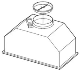
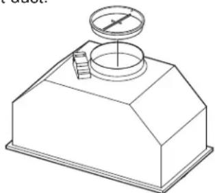
- Insert the damper assembly into the hood exhaust duct.
natural_image
Technical line drawing of a mechanical component with a cylindrical top and flange base (no text or symbols)- The hood should be centered left to right over the cooktop.
NOTE: The exhaust duct on the hood is closer to the rear of the hood. It is important to plan for the alignment to the connection point of the hood.
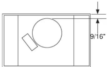
- The back surface of the hood must be 1" minimum from the back wall. The front surface of the hood must be 3" minimum from the front custom cabinet panel.
- The metal liner should be used when the hood installation height is less than 30". The liner dimensions are provided in the Product Dimensions section.
- The electrical receptacle location maximum dimension is shown here.
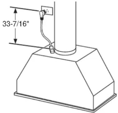
- The custom cabinet should provide for removal of panels to provide access to the electrical cord plug and to the ducting and its connection to the hood in case of any need for servicing or other reasons.
PREPARE FOR ISLAND INSTALLATION
- Insert the damper assembly into the hood exhaust duct.
natural_image
Isometric line drawing of a mechanical device with a cylindrical top and base (no text or symbols)- The hood should be centered left to right over the cooktop.
NOTE: The exhaust duct on the hood is closer to the rear of the hood.
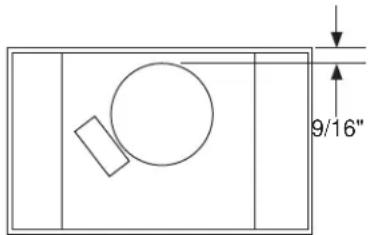
The front to back location of the hood over the cooktop can be chosen by the installer or homeowner. The island duct run is usually centered over the cooktop and it is important to plan for the alignment to the connection point of the hood.
- The metal liner should be used when the hood installation height is less than 30". The liner dimensions are provided in the Product Dimensions section.
- Locate the electrical receptacle in the cabinetry or area above the hood so that it complies with local and electrical codes.
- The custom cabinet should provide for removal of panels to provide access to the electrical cord plug and to the ducting and its connection to the hood in case of any need for servicing or other reasons.
STEP 1 | INSTALL HOOD LINER (If Used)
- The rectangular opening in framing or custom cabinet must be sized for the liner outside and inside dimensions. Refer to Product Dimensions section.
- Secure the liner with the 4 screws that are provided with the liner.
natural_image
Technical line drawing of a 3D mechanical housing or enclosure with internal compartments and a circular opening (no text or symbols)STEP 2 | INSTALL THE HOOD
- Confirm the damper is in place in the hood exhaust opening.
- Insert the hood and power cord into the cabinet opening or into the liner opening.
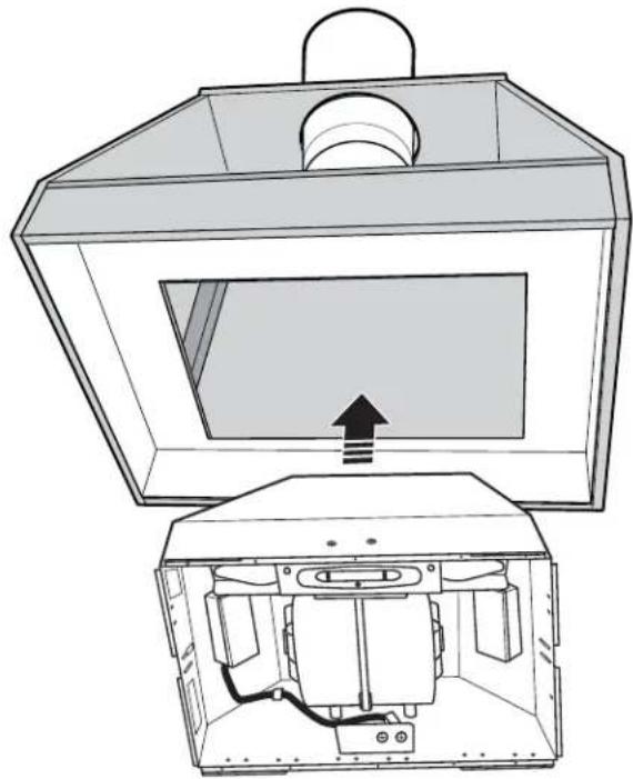
natural_image
Technical line drawing of a mechanical device with internal components and an upward arrow indicating motion (no text or symbols)STEP 2 INSTALL THE HOOD (Cont)
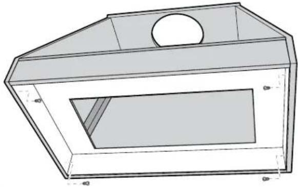
- Fasten with 4 screws. There is a spring locking clip on one side of the hood to assist with holding one side up while installing the screws.
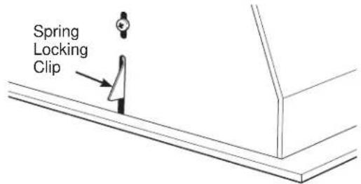
NOTE: 4 screws can be installed into the sides or into the front and back holes in the hood.
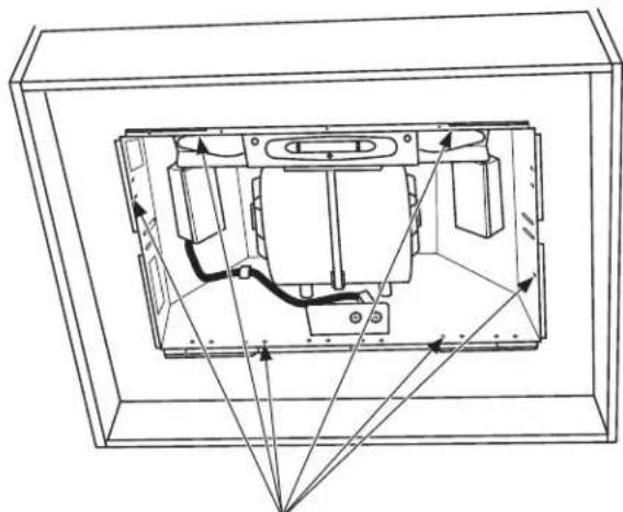
natural_image
Technical line drawing of a mechanical assembly inside a transparent enclosure, showing internal components and directional arrows (no text or symbols)Possible screw locations
- If the liner is used, an alternate mounting method is to assemble the hood to the liner using the 4 machine screws, washers, and nuts provided. Then assemble the liner to the framing or custom cabinet using the 4 screws provided with the liner.
- Once the hood is in place, seal the duct to the hood with duct tape.
STEP 3 RECIRCULATION KIT (If Used)
- Cut a hole into the soffit for the exhaust duct.
- Install the vent grill over the exhaust duct.
- Seal the duct joints with duct tape.
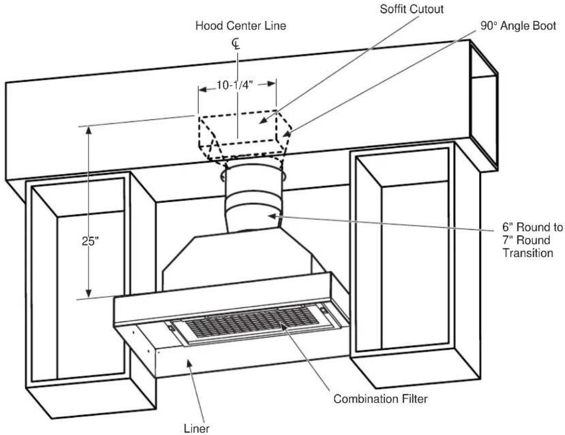
STEP 4 | FINALIZE INSTALLATION
- Plug in the hood.
- Install the access panel.
- Check operation of the lights and blower.
- Finish the custom cabinetry.
Troubleshooting tips ... Before you call for service
Save time and money! Review the charts on the following pages first and you may not need to call for service.
| Problem Possible Cause | What To Do | |
| Fan/Light does not operate when slide switch is turned ON | A house fuse may be blown or a circuit breaker tripped. | Replace fuse or reset circuit breaker. |
| Loud or abnormal airflow noise | Wrong duct size used in installation. | This hood requires 6" ducting to perform optimally. Using smaller duct pipe will cause reduced venting. Minimize the duct run length and number of transitions and elbows. GE service technicians cannot correct this issue if installed improperly. |
| Fan fails to circulate air or moves air slower than normal and/or fan is making loud or abnormal airflow noise | Obstructions in duct work. Make sure nothing is blocking the vent. Make sure your wall or roof cap has a blade or door. | |
| Damper blade on wall or roof cap may not be open. | Make sure damper swings freely. Damper blades may flip over and will not fully open when this happens. Adjust to original position. | |
| Metal grease filter and charcoal filter (if present) may be dirty. | Clean the metal grease filter and replace charcoal filter (if present). See Care and Cleaning of the Vent Hood. | |
| Insufficient makeup (replacement) air | Sufficient makeup (replacement) air is required for exhausting appliances to operate to rating. Check with local building codes, which may require or strongly advise the use of makeup air. Visit GEAppliances.com for available makeup air solutions. | |
| Early light failure Light wattage is too high. Replace with correct wattage. | ||
| Fan automatically turns on and can not be turned off. | This is normal. The sensor feature will automatically turn the fan on if cooking temperature becomes too hot. The fan will then turn off when temperatures cool to an appropriate level. | |
| Fan keeps going off and on | The motor is probably overheating and turning itself off. This can be harmful to the motor. | Check to be sure the filters are clean. If off and on cycling continues, call for service. |
Hotte Encastrable Et Adaptable
www.geappliances.com/service_and_support/register/
Garant : General Electric Company. Louisville, KY 40225
www.geappliances.com/service and support/shop-for-extended-service-plans.htm
General Manager, Customer Relations GE Appliances, Appliance Park Louisville, KY 40225
Accessoires
DIMENSIONS DU PRODUIT
natural_image
Isometric line drawing of a ceiling-mounted air vent with grating and ventilation slots (no text or symbols)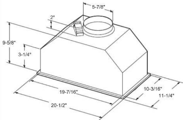
Jupes (facultatif)
DÉGAGEMENTS DE L'INSTALLATION
natural_image
Illustration of a power drill with multiple drill bits and a terminal plug (no text or symbols)natural_image
Isometric line drawing of a hot air heater with ventilation grilles and a handle (no text or symbols)PLANIFIER L'INSTALLATION
ATTENTION
natural_image
Technical line drawing of a mechanical component with a cylindrical top and base (no text or symbols)natural_image
Technical line drawing of a mechanical device with a cylindrical component and base (no text or symbols)natural_image
Technical line drawing of a 3D box-like structure with a circular top and rectangular opening (no text or symbols)ÉTAPE 2 | INSTALLER LA HOTTE
natural_image
Technical line drawing of a device with an open top and internal compartments, showing internal components and a directional arrow (no text or symbols)ÉTAPE 2 | INSTALLER LA HOTTE (suite)
natural_image
Technical line drawing of an internal mechanical or electrical component enclosed in a transparent enclosure, with no visible text or symbols.www.geappliances.com/service_and_support/register/
Garante: General Electric Company. Louisville, KY 40225
www.geappliances.com/service_and_support/shop-for-extended-service-plans.htm
General Manager, Customer Relations GE Appliances, Appliance Park Louisville, KY 40225
Accesorios
¿Busca Algo Más?
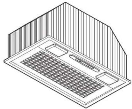
DIMENSIONES DEL PRODUCTO
natural_image
Isometric line drawing of a ceiling-mounted air vent with grating and ventilation slots (no text or symbols)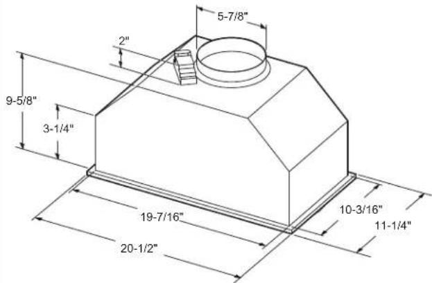
Cobertores (Opcional)
This vent hood and liner assembly must be installed 24" required minimum and 36" recommended maximum above the cooking surface.
natural_image
Line drawing of a handheld electric drill with multiple drill bits and a power plug (no text or symbols)natural_image
Isometric line drawing of a campan with ventilation grilles and ventilation slots (no text or symbols)PLAN DE INSTALACIÓN
PRECAUCIÓN
natural_image
Technical line drawing of a mechanical component with a cylindrical top and base (no text or symbols)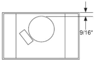
natural_image
Isometric line drawing of a mechanical device with a cylindrical top and base (no text or symbols)natural_image
Technical line drawing of a 3D mechanical housing or enclosure with a circular top opening and internal cavity (no text or symbols)natural_image
Technical line drawing of a device with an open top and internal compartments, showing internal wiring (no text or symbols)- IMPORTANT SAFETY INFORMATION. READ ALL INSTRUCTIONS BEFORE USING.
- SAFETY PRECAUTIONS
- WARNING
- SAFETY PRECAUTIONS (Cont.)
- TO REDUCE THE RISK OF A P GREASE FIRE:
- TO REDUCE THE RISK OF FIRE, SHOCK OR INJURY TO PERSONS, THE FOLLOWING:
- TO REDUCE THE RISK OF FIRE, METAL DUCTWORK.
- Thank You! ... for your purchase of a GE Brand appliance.
- GE Warranty
- GEAppliances.com
- What GE will not cover:
- EXCLUSION OF IMPLIED WARRANTIES
- Warrantor: General Electric Company. Louisville, KY 40225
- Have a question or need assistance with your appliance?
- Accessories
- How to Remove Protective Shipping Film and Packaging Tape
- Controls
- Heat Sensor
- Filters
- Metal Grease Filter
- To remove:
- To replace:
- For Recirculation Installation Only
- Charcoal Filter (Not Included)
- Surfaces
- Painted Surfaces
- CAUTION
- Light Bulbs
- Allow lights to cool before
- touching.
- To change the light bulbs:
- BULB MAY BE HOT!
- Installation Instructions
- Custom Hood Insert
- BEFORE YOU BEGIN
- TWO PEOPLE ARE
- FOR YOUR SAFETY:
- TO REDUCE THE RISK OF
- FIRE, ELECTRIC SHOCK OR INJURY TO PERSONS, OBSERVE THE FOLLOWING:
- INSTALLATION CLEARANCES
- ADVANCE PLANNING
- Duct Install Planning
- Wall and Ceiling Framing for Adequate Support
- Custom Cabinet Frame Planning
- Metal Liners
- Recirculation Install Planning
- Power Supply Planning
- POWER SUPPLY
- IMPORTANT – (Please read carefully)
- FOR PERSONAL SAFETY, THIS APPLIANCE MUST BE PROPERLY GROUNDED.
- Electrical supply
- TOOLS AND MATERIALS REQUIRED
- PARTS PROVIDED
- PLAN THE INSTALLATION
- PERSONAL INJURY HAZARD
- REMOVE THE PACKAGING
- PREPARE FOR CABINET INSTALLATION
- PREPARE FOR ISLAND INSTALLATION
- STEP 1 | INSTALL HOOD LINER (If Used)
- STEP 2 | INSTALL THE HOOD
- STEP 2 INSTALL THE HOOD (Cont)
- STEP 3 RECIRCULATION KIT (If Used)
- STEP 4 | FINALIZE INSTALLATION
- Troubleshooting tips ... Before you call for service
- Hotte Encastrable Et Adaptable
- Garant : General Electric Company. Louisville, KY 40225
- Accessoires
- DÉGAGEMENTS DE L'INSTALLATION
- PLANIFIER L'INSTALLATION
- ATTENTION
- ÉTAPE 2 | INSTALLER LA HOTTE
- ÉTAPE 2 | INSTALLER LA HOTTE (suite)
- Garante: General Electric Company. Louisville, KY 40225
- Accesorios
- PLAN DE INSTALACIÓN
- PRECAUCIÓN
Brand : GE
Model : JVC3300JSA
Category : Range hood