USER MANUAL 970 Pro3 ASROCK
No part of this installation guide may be reproduced, transcribed, transmitted, or translated in any language, in any form or by any means, except duplication of documentation by the purchaser for backup purpose, without written consent of ASRock Inc.
Products and corporate names appearing in this guide may or may not be registered trademarks or copyrights of their respective companies, and are used only for identification or explanation and to the owners' benefit, without intent to infringe.
Disclaimer:
Specifications and information contained in this guide are furnished for informational use only and subject to change without notice, and should not be constructed as a commitment by ASRock. ASRock assumes no responsibility for any errors or omissions that may appear in this guide.
With respect to the contents of this guide, ASRock does not provide warranty of any kind, either expressed or implied, including but not limited to the implied warranties or conditions of merchantability or fitness for a particular purpose. In no event shall ASRock, its directors, officers, employees, or agents be liable for any indirect, special, incidental, or consequential damages (including damages for loss of profits, loss of business, loss of data, interruption of business and the like), even if ASRock has been advised of the possibility of such damages arising from any defect or error in the guide or product.

This device complies with Part 15 of the FCC Rules. Operation is subject to the following two conditions:
(1) this device may not cause harmful interference, and
(2) this device must accept any interference received, including interference that may cause undesired operation.
CALIFORNIA, USA ONLY
The Lithium battery adopted on this motherboard contains Perchlorate, a toxic substance controlled in Perchlorate Best Management Practices (BMP) regulations passed by the California Legislature. When you discard the Lithium battery in California, USA, please follow the related regulations in advance.
"Perchlorate Material-special handling may apply, see www.dtsc.ca.gov/hazardouswaste/perchlorate"
ASRock Website: http://www.asrock.com
Published April 2012
Copyright ©2012 ASRock INC. All rights reserved.
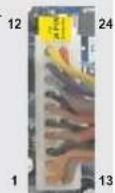
Motherboard Layout
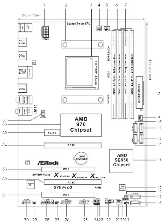
1ATX12VPower Connector (ATX12V1) 19 Power LED Header (PLED1)
2 CPU Heatsink Retention Module 20 Chassis Speaker Header (SPEAKER 1, Black)
3 AM3+ CPU Socket 21 Chassis Fan Connector (CHA_FAN2)
4 CPU Fan Connector (CPU_FAN2) 22 System Panel Header (PANEL1, Black)
5 CPU Fan Connector (CPU_FAN1) 23 USB 2.0 Header (USB_6_7, Black)
6 2 x 240-pin DDR3 DIMM Slots 24 Consumer Infrared Module Header (CIR1)
(Dual Channel: DDR3_A1, DDR3_B1; Black) 25 USB 2.0 Header (USB_8_9, Black)
7 2 x 240-pin DDR3 DIMM Slots 26 USB 2.0 Header (USB_10_11, Black)
(Dual Channel: DDR3_A2, DDR3_B2; Black) 27 Infrared Module Header
8ATXPowerConnector(ATXPWR1)28COMPortHeader(COM1)
9 Power Fan Connector (PWR_FAN1) 29 HDMI_SPDIF Header (HDMI_SPDIF1, Black)
10 SATA3 Connector (SATA3_5, Gray) 30 Front Panel Audio Header
11 SATA3 Connector (SATA3_6, Gray) (HD=AUDIO1, Black)
12 SATA3 Connector (SATA3_4, Gray) 31 PCI Slot (PCI2)
13 SATA3 Connector (SATA3_3, Gray) 32 PCI Express 2.0 x16 Slot (PCIE3; Black)
14 Southbridge Controller 33 PCI Slot (PCI1)
15 SPI Flash Memory (32Mb) 34 PCI Express 2.0 x16 Slot (PCIE2; Black)
16 Clear CMOS Jumper (CLRCMOS1) 35 PCI Express 2.0 x1 Slot (PCIE1; Black)
17 SATA3 Connector (SATA3_2, Gray) 36 Northbridge Controller
18 SATA3 Connector (SATA3_1, Gray) 37 Chassis Fan Connector (CHA_FAN1)
I/O Panel
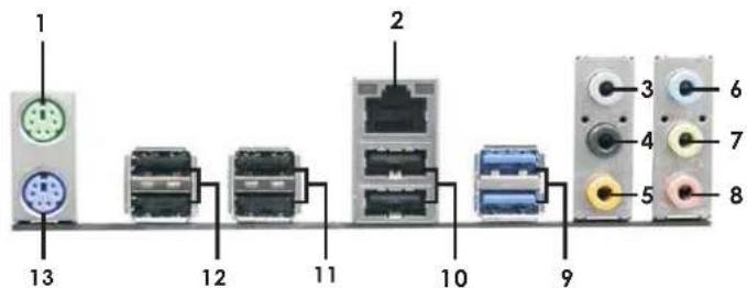
1 PS/2 Mouse Port (Green)
^2 LAN RJ-45 Port
3 Side Speaker (Gray)
4 Rear Speaker (Black)
5 Central/Bass (Orange)
6 Line In (Light Blue)
*7 Front Speaker (Lime)
8 Microphone (Pink)
9 USB3.0 Port (USB3_0_1)
10 USB 2.0 Port (USB_4_5)
11 USB 2.0 Port (USB_2_3)
12 USB 2.0 Port (USB_0_1)
13 PS/2 Keyboard Port (Purple)
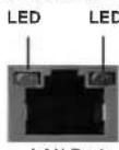
- There are two LED next to the LAN port. Please refer to the table below for the LAN port LED indications.
LAN Port LED Indications
| Activity/Link LED |
| Status | Description |
| Off | No Link |
| Blinking | Data Activity |
| On | Link |
ACT/LINK SPEED
| Status | Description |
| Off | 10Mbps connection |
| Orange | 100Mbps connection |
| Green | 1Gbps connection |
** If you use 2-channel speaker, please connect the speaker's plug into "Front Speaker Jack". See the table below for connection details in accordance with the type of speaker you use.
TABLE for Audio Output Connection
| Audio Output Channels
(No. 7) (No. 4) (No. 5) | Front Speaker
(No. 3) | Rear Speaker | Central / Bass Side | Speaker |
| 2 | | V | -- | -- |
| 4 | V | V | -- | |
| 6 | | V | V | V |
| 8 | | V | V | V |
To enable Multi-Streaming function, you need to connect a front panel audio cable to the front panel audio header. After restarting your computer, you will find "Mixer" tool on your system. Please select "Mixer ToolBox", click "Enable playback multi-streaming", and click "ok".
, click "Enable playback multi-streaming", and click "ok".
Choose "2CH", "4CH", "6CH", or "8CH" and then you are allowed to select "Realtek HDA Primary output" to use Rear Speaker, Central/Bass, and Front Speaker, or select "Realtek HDA Audio 2nd output" to use front panel audio.
English
1. Introduction
Thank you for purchasing ASRock 970 Pro3 motherboard, a reliable motherboard produced under ASRock's consistently stringent quality control. It delivers excellent performance with robust design conforming to ASRock's commitment to quality and endurance.
This Quick Installation Guide contains introduction of the motherboard and step-by-step installation guide. More detailed information of the motherboard can be found in the user manual presented in the Support CD.

Because the motherboard specifications and the BIOS software might be updated, the content of this manual will be subject to change without notice. In case any modifications of this manual occur, the updated version will be available on ASRock website without further notice. You may find the latest VGA cards and CPU support lists on ASRock website as well. ASRock website http://www.asrock.com
If you require technical support related to this motherboard, please visit our website for specific information about the model you are using. www.asrock.com/support/index.asp
1.1 Package Contents
ASRock 970 Pro3 Motherboard
(ATX Form Factor: 12.0-in x 8.2-in, 30.5 cm x 20.8 cm)
ASRock 970 Pro3 Quick Installation Guide
ASRock 970 Pro3 Support CD
2 x Serial ATA (SATA) Data Cables (Optional)
1 x I/O Panel Shield

ASRock Reminds You...
To get better performance in Windows® 7 / 7 64-bit / Vista™ / Vista™ 64 bit, it is recommended to set the BIOS option in Storage Configuration to AHCI mode. For the BIOS setup, please refer to the "User Manual" in our support CD for details.
1.2 Specifications
| Platform - ATX Form Factor: 12.0-in x 8.2-in, 30.5 cm x 20.8 cm
- All Solid Capacitor design |
| CPU - Support for Socket AM3+ processors
- Support for Socket AM3 processors: AMD Phenom ™ II X6 / X4 / X3 / X2 (except 920 / 940) / Athlon II X4 / X3 / X2 /
Sempron processors
- Supports 8-Core CPU
- Supports UCC feature (Unlock CPU Core) (see CAUTION 1)
- 4 + 1 Power Phase Design
- Supports CPU up to 140W
- Supports AMD's Cool 'n' Quiet ™ Technology
- FSB 2400 MHz (4.8 GT/s)
- Supports Untied Overclocking Technology (see CAUTION 2)
- Supports Hyper-Transport 3.0 (HT 3.0) Technology |
| Chipset - Northbridge: AMD 970
- Southbridge: AMD SB950 |
| Memory - Dual Channel DDR3 Memory Technology (see CAUTION 3)
- 4 x DDR3 DIMM slots
- Support DDR3 2100(OC)/1866(OC)/1800(OC)/1600(OC)/1333/1066/800 non-ECC, un-buffered memory
(see CAUTION 4)
- Max. capacity of system memory: 32GB (see CAUTION 5) |
| Expansion Slot - 2 x PCI Express 2.0 x16 slots
(PCIE2 @ x16 mode; PCIE3 @ x4 mode)
- 1 x PCI Express 2.0 x1 slot
- 2 x PCI slots
- Supports AMD Quad CrossFireX ™ and CrossFireX™ |
| Audio - 7.1 CH HD Audio with Content Protection
(Realtek ALC892 Audio Codec)
- Premium Blu-ray audio support
- Supports THX TruStudio ™ |
| LAN - PCIE x1 Gigabit LAN 10/100/1000 Mb/s
- Realtek RTL8111E
- Supports Wake-On-LAN
- Supports LAN Cable Detection
- Supports PXE
- Supports Energy Efficient Ethernet 802.3az |
| Rear Panel I/O I/Q Panel
- 1 x PS/2 Mouse Port
- 1 x PS/2 Keyboard Port
- 6 x Ready-to-Use USB 2.0 Ports
- 2 x Ready-to-Use USB 3.0 Ports
- 1 x RJ-45 LAN Port with LED (ACT/LINK LED and SPEED LED)
- HD Audio Jack: Side Speaker/Rear Speaker/Central/Bass/
Line in/ Front Speaker/Microphone (see CAUTION 6) |
| SATA3 - 6 x SATA3 6.0 Gb/s connectors, support RAID (RAID 0, RAID 1, RAID 5 and RAID 10), NCQ, AHCI and "Hot Plug" functions |
| USB 3.0 - 2 x USB up to 5Gb/s 3.0 ports by Etron EJ168A, support USB 1.0/2.0/3.0 |
| Connector - 6 x SATA3 6.0Gb/s connectors
- 1 x IR header
- 1 x CIR header
- 1 x COM port header
- 1 x HDMI_SPDIF header
- 1 x Power LED header
- 2 x CPU Fan connectors (1 x 4-pin, 1 x 3-pin)
- 2 x Chassis Fan connectors (1 x 4-pin, 1 x 3-pin)
- 1 x Power Fan connector (3-pin)
- 24 pin ATX power connector
- 8 pin 12V power connector
- Front panel audio connector
- 3 x USB 2.0 headers (support 6 USB 2.0 ports) |
| BIOS Feature - 32 Mb AMI UEFI Legal BIOS with GUI support
- Supports "Plug and Play"
- ACPI 1.1 Compliance Wake Up Events
- Supports jumperfree
- SMBIOS 2.3.1 Support
- CPU, VCCM, NB, SB Voltage Multi-adjustment |
| Support CD - Drivers, Utilities, AntiVirus Software (Trial Version),
CyberLink Media ESPresso 6.5 Trial, AMD OverDrive™ Utility
AMD Fusion, AMD Fusion Media Explorer, ASRock MAGIX
Multimedia Suite - OEM |
| Unique Feature | - ASRock Extreme Tuning Utility (AXTU) (see CAUTION 7) |
| - ASRock Instant | Boot |
| - ASRock Instant | Flash (see CAUTION 8) |
| - ASRock APP Charger | (see CAUTION 9) |
| - ASRock SmartView | (see CAUTION 10) |
| - ASRock XFast USB | (see CAUTION 11) |
| - ASRock XFast LAN | (see CAUTION 12) |
| - ASRock XFast RAM | (see CAUTION 13) |
| - ASRock Crashless BIOS | (see CAUTION 14) |
| - ASRock OMG (Online Management Guard) |
| (see CAUTION 15) |
| - ASRock Internet | Flash (see CAUTION 16) |
| - ASRock On/Off | Play Technology (see CAUTION 17) |
| - Hybrid Booster: |
| - CPU Frequency Stepless Control | (see CAUTION 18) |
| - ASRock U-COP | (see CAUTION 19) |
| - Boot Failure Guard (B.F.G.) |
| Turbo | UCC |
| Hardware - CPU | Temperature Sensing |
| Monitor - Chassis | Temperature Sensing |
| - CPU/Chassis/Power Fan Tachometer |
| - CPU/Chassis Quiet Fan |
| - CPU/Chassis Fan Multi-Speed Control |
| - Voltage Monitoring: +12V, +5V, +3.3V, Vcore |
| OS / XP 64-bit comp | Window 70070064-bit / VistaTM / VistaTM 64-bit / XP pliant (see CAUTION 20) |
| Certifications | - FCC, CE, WHQL |
| - ErP/EuP Ready | (ErP/EuP ready power supply is required) |
| (see CAUTION 21) |
- For detailed product information, please visit our website: http://www.asrock.com
WARNING
Please realize that there is a certain risk involved with overclocking, including adjusting the setting in the BIOS, applying Untied Overclocking Technology, or using the third-party overclocking tools. Overclocking may affect your system stability, or even cause damage to the components and devices of your system. It should be done at your own risk and expense. We are not responsible for possible damage caused by overclocking.
CAUTION!
- ASRock UCC (Unlock CPU Core) feature simplifies AMD CPU activation. As long as a simple switch of the UEFI option "ASRock UCC", you can unlock the extra CPU core to enjoy an instant performance boost. When UCC feature is enabled, the dual-core or triple-core CPU will boost to the quad-core CPU, and some CPU, including quad-core CPU, can also increase L3 cache size up to 6MB, which means you can enjoy the upgrade CPU performance with a better price. Please be noted that UCC feature is supported with AM3/AM3+ CPU only, and in addition, not every AM3/AM3+ CPU can support this function because some CPU's hidden core may be malfunctioned.
- This motherboard supports Untied Overclocking Technology. Please read "Untied Overclocking Technology" on page 29 for details.
- This motherboard supports Dual Channel Memory Technology. Before you implement Dual Channel Memory Technology, make sure to read the installation guide of memory modules on page 13 for proper installation.
- Whether 2100/1866/1800/1600MHz memory speed is supported depends on the AM3/AM3+ CPU you adopt. If you want to adopt DDR3 2100/1866/1800/1600 memory module on this motherboard, please refer to the memory support list on our website for the compatible memory modules. Non OC mode's DDR3 1866 is supported by AM3+ CPU.
ASRock website: http://www.asrock.com
- Due to the operating system limitation, the actual memory size may be less than 4GB for the reservation for system usage under Windows® 7 / Vista™ / XP. For Windows® 64-bit OS with 64-bit CPU, there is no such limitation. You can use ASRock XFast RAM to utilize the memory that Windows® cannot use.
- For microphone input, this motherboard supports both stereo and mono modes. For audio output, this motherboard supports 2-channel, 4-channel, 6-channel, and 8-channel modes. Please check the table on page 3 for proper connection.
- ASRock Extreme Tuning Utility (AXTU) is an all-in-one tool to ne-tune different system functions in a user-friendly interface, which is including Hardware Monitor, Fan Control, Overclocking, OC DNA and IES. In Hardware Monitor, it shows the major readings of your system. In Fan Control, it shows the fan speed and temperature for you to adjust. In Overclocking, you are allowed to overclock CPU frequency for optimal system performance. In OC DNA, you can save your OC settings as a profile and share with your friends. Your friends then can load the OC profile to their own system to get the same OC settings. In IES (Intelligent Energy Saver), the voltage regulator can reduce the number of output phases to improve efficiency when the CPU cores are idle without sacrificing computing performance. Please visit our website for the operation procedures of ASRock Extreme Tuning Utility (AXTU).
ASRock website: http://www.asrock.com
- ASRock Instant Flash is a BIOS flash utility embedded in Flash ROM. This convenient BIOS update tool allows you to update system BIOS without entering operating systems first like MS-DOS or Windows®. With this utility, you can press key during the POST or press key to BIOS setup menu to access ASRock Instant Flash. Just launch this tool and save the new BIOS file to your USB flash drive, floppy disk or hard drive, then you can update your BIOS only in a few clicks without preparing an additional floppy diskette or other complicated flash utility. Please be noted that the USB flash drive or hard drive must use FAT32/16/12 file system.
- If you desire a faster, less restricted way of charging your Apple devices, such as iPhone/iPod/iPad Touch, ASRock has prepared a wonderful solution for you - ASRock APP Charger. Simply installing the APP Charger driver, it makes your iPhone charged much quickly from your computer and up to 40% faster than before. ASRock APP Charger allows you to quickly charge many Apple devices simultaneously and even supports continuous charging when your PC enters into Standby mode (S1), Suspend to RAM (S3), hibernation mode (S4) or power off (S5). With APP Charger driver installed, you can easily enjoy the marvelous charging experience than ever.
ASRock website: http://www.asrock.com/Feature/AppCharger/index.asp
10. ASRock SmartView, a new function of internet browser, is the smart start page for IE that combines your most visited web sites, your history, your Facebook friends and your real-time newsfeed into an enhanced view for a more personal Internet experience. ASRock motherboards are exclusively equipped with the ASRock SmartView utility that helps you keep in touch with friends on-the-go. To use ASRock SmartView feature, please make sure your OS version is Windows® 7 / 7 64 bit / Vista™ / Vista™ 64 bit, and your browser version is IE8.
ASRock website: http://www.asrock.com/Feature/SmartView/index.asp
- ASRock XFast USB can boost USB storage device performance. The performance may depend on the property of the device.
- ASRock XFast LAN provides a faster internet access, which includes below benefits. LAN Application Prioritization: You can configure your application priority ideally and/or add new programs. Lower Latency in Game: After setting online game priority higher, it can lower the latency in game. Traffic Shaping: You can watch Youtube HD video and download files simultaneously. Real-Time Analysis of Your Data: With the status window, you can easily recognize which data streams you are currently transferring.
- ASRock XFast RAM is a new function that is included into ASRock Extreme Tuning Utility (AXTU). It fully utilizes the memory space that cannot be used under Windows OS 32-bit CPU. ASRock XFast RAM shortens the loading time of previously visited websites, making web surfing faster than ever. And it also boosts the speed of Adobe Photoshop 5 times faster. Another advantage of ASRock XFast RAM is that it reduces the
frequency of accessing your SSDs or HDDs in order to extend their lifespan.
- ASRock Crashless BIOS allows users to update their BIOS without fear of failing. If power loss occurs during the BIOS update process, ASRock Crashless BIOS will automatically finish the BIOS update procedure after regaining power. Please note that BIOS files need to be placed in the root directory of your USB disk. Only USB2.0 ports support this feature.
- Administrators are able to establish an internet curfew or restrict internet access at specified times via OMG. You may schedule the starting and ending hours of internet access granted to other users. In order to prevent users from bypassing OMG, guest accounts without permission to modify the system time are required.
- ASRock Internet Flash searches for available UEFI firmware updates from our servers. In other words, the system can auto-detect the latest UEFI from our servers and flash them without entering Windows® OS. Please note that you must be running on a DHCP configured computer in order to enable this function.
- ASRock On/Off Play Technology allows users to enjoy the great audio experience from the portable audio devices, such like MP3 player or mobile phone to your PC, even when the PC is turned off (or in ACPI S5 mode)! This motherboard also provides a free 3.5mm audio cable (optional) that ensures users the most convenient computing environment.
- Although this motherboard offers stepless control, it is not recommended to perform over-clocking. Frequencies other than the recommended CPU bus frequencies may cause the instability of the system or damage the CPU.
- While CPU overheat is detected, the system will automatically shutdown. Before you resume the system, please check if the CPU fan on the motherboard functions properly and unplug the power cord, then plug it back again. To improve heat dissipation, remember to spray thermal grease between the CPU and the heatsink when you install the PC system.
- ASRock XFast RAM is not supported by Microsoft Windows XP / XP 64-bit.
- EuP, stands for Energy Using Product, was a provision regulated by European Union to define the power consumption for the completed system. According to EuP, the total AC power of the completed system shall be under 1.00W in off mode condition. To meet EuP standard, an EuP ready motherboard and an EuP ready power supply are required. According to Intel's suggestion, the EuP ready power supply must meet the standard of 5v standby power efficiency is higher than 50% under 100 mA current consumption. For EuP ready power supply selection, we recommend you checking with the power supply manufacturer for more details.
2. Installation
This is an ATX form factor (12.0-in x 8.2-in, 30.5cm× 20.8cm ) motherboard. Before you install the motherboard, study the configuration of your chassis to ensure that the motherboard fits into it.
Pre-installation Precautions
Take note of the following precautions before you install motherboard components or change any motherboard settings.

Before you install or remove any component, ensure that the power is switched off or the power cord is detached from the power supply. Failure to do so may cause severe damage to the motherboard, peripherals, and/or components.
- Unplug the power cord from the wall socket before touching any component.
- To avoid damaging the motherboard components due to static electricity, NEVER place your motherboard directly on the carpet or the like. Also remember to use a grounded wrist strap or touch a safety grounded object before you handle components.
- Hold components by the edges and do not touch the ICs.
- Whenever you uninstall any component, place it on a grounded anti-static pad or in the bag that comes with the component.
- When placing screws into the screw holes to secure the motherboard to the chassis, please do not over-tighten the screws! Doing so may damage the motherboard.
2.1 CPU Installation
Step 1. Unlock the socket by lifting the lever up to a 90° angle.
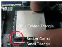
Step 2. Position the CPU directly above the socket such that the CPU corner with the golden triangle matches the socket corner with a small triangle.
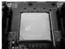
Step 3. Carefully insert the CPU into the socket until it fits in place.

The CPU fits only in one correct orientation. DO NOT force the CPU into the socket to avoid bending of the pins.
Step 4. When the CPU is in place, press it firmly on the socket while you push down the socket lever to secure the CPU. The lever clicks on the side tab to indicate that it is locked.
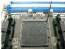
STEP1: Lift Up The Socket Lever
STEP 2 / STEP 3:
Match The CPU Golden Triangle
To The Socket Corner Small Triangle
STEP 4: Push Down And Lock The Socket Lever
2.2 Installation of CPU Fan and Heatsink
After you install the CPU into this motherboard, it is necessary to install a larger heatsink and cooling fan to dissipate heat. You also need to spray thermal grease between the CPU and the heatsink to improve heat dissipation. Make sure that the CPU and the heatsink are securely fastened and in good contact with each other. Then connect the CPU fan to the CPU FAN connector (CPU_FAN1, see Page 2, No. 5 or CPU_FAN2, see Page 2, No. 4). For proper installation, please kindly refer to the instruction manuals of the CPU fan and the heatsink.
2.3 Installation of Memory Modules (DIMM)
This motherboard provides four 240-pin DDR3 (Double Data Rate 3) DIMM slots, and supports Dual Channel Memory Technology. For dual channel configuration, you always need to install identical (the same brand, speed, size and chip-type) DDR3 DIMM pair in the slots. In other words, you have to install identical DDR3 DIMM pair in Dual Channel (DDR3_A1 and DDR3_B1; Black slots; see p.2 No.6) or identical DDR3 DIMM pair in Dual Channel (DDR3_A2 and DDR3_B2; Black slots; see p.2 No.7), so that Dual Channel Memory Technology can be activated. This motherboard also allows you to install four DDR3 DIMMs for dual channel configuration, and please install identical DDR3 DIMMs in all four slots. You may refer to the Dual Channel Memory Confi guration Table below.
Dual Channel Memory Configurations
| DDR3_A1 DDR3_ Black Slot) (Black Slot) (Black Slot) (Black Slot) |
| (1) Populated | - Populated | - | |
| (2) | - | Populated | - | Populated |
| (3)* | Populated | Populated | Populated | Populated |
For the configuration (3), please install identical DDR3 DIMMs in all four
slots.

- Please install the memory module into the slots DDR3_A2 and DDR3_B2 for the first priority.
- If you want to install two memory modules, for optimal compatibility and reliability, it is recommended to install them either in the set of slots DDR3_A1 and DDR3_B1, or in the set of slots DDR3_A2 and DDR3_B2.
- If only one memory module or three memory modules are installed in the DDR3 DIMM slots on this motherboard, it is unable to activate the Dual Channel Memory Technology.
- If a pair of memory modules is NOT installed in the same Dual Channel, for example, installing a pair of memory modules in DDR3_A1 and DDR3_A2, it is unable to activate the Dual Channel Memory Technology.
- It is not allowed to install a DDR or DDR2 memory module into DDR3 slot; otherwise, this motherboard and DIMM may be damaged.
- If you adopt DDR3 2100/1866/1800/1600 memory modules on this motherboard, it is recommended to install them on DDR3_A2 and DDR3_B2 slots.
English
Installing a DIMM

Please make sure to disconnect power supply before adding or removing DIMMs or the system components.
Step 1. Unlock a DIMM slot by pressing the retaining clips outward.
Step 2. Align a DIMM on the slot such that the notch on the DIMM matches the break on the slot.
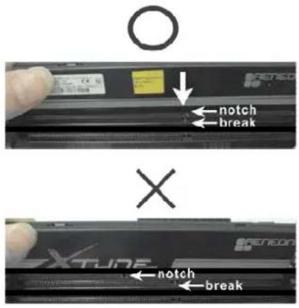

The DIMM only fits in one correct orientation. It will cause permanent damage to the motherboard and the DIMM if you force the DIMM into the slot at incorrect orientation.
Step 3. Firmly insert the DIMM into the slot until the retaining clips at both ends fully snap back in place and the DIMM is properly seated.
2.4 Expansion Slots (PCI and PCI Express Slots)
There are 2 PCI slots and 3 PCI Express slots on this motherboard.
PCI Slots: PCI slots are used to install expansion cards that have the 32-bit PCI interface.
PCIE Slots:
PCIE1 (PCIE x1 slot; Black) is used for PCI Express cards with x1 lane width cards, such as Gigabit LAN card and SATA2 card.
PCIE2 (PCIE x16 slot; Black) is used for PCI Express x16 lane width graphics cards, or used to install PCI Express graphics cards to support CrossFireXTM function.
PCIE3 (PCIE x16 slot; Black) is used for PCI Express x4 lane width cards, or used to install PCI Express graphics cards to support CrossFireXTM function.

- In single VGA card mode, it is recommended to install a PCI Express x16 graphics card on PCIE2 slot.
- In CrossFireTM mode, please install PC1 Express x16 graphics cards on PCIE2 and PCIE3 slots. Therefore, PCIE2 slot will work at x16 bandwidth while PCIE3 slot will work at x4 bandwidth.
- Please connect a chassis fan to motherboard chassis fan connector (CHA_FAN1 or CHA_FAN2) when using multiple graphics cards for better thermal environment.
Installing an expansion card
Step 1. Before installing the expansion card, please make sure that the power supply is switched off or the power cord is unplugged. Please read the documentation of the expansion card and make necessary hardware settings for the card before you start the installation.
Step 2. Remove the system unit cover (if your motherboard is already installed in a chassis).
Step 3. Remove the bracket facing the slot that you intend to use. Keep the screws for later use.
Step 4. Align the card connector with the slot and press firmly until the card is completely seated on the slot.
Step 5. Fasten the card to the chassis with screws.
Step 6. Replace the system cover.
2.5 CrossFireX™ and Quad CrossFireX™ Operation Guide
This motherboard supports CrossFireX™ and Quad CrossFireX™ feature. CrossFireX™ technology offers the most advantageous means available of combining multiple high performance Graphics Processing Units (GPU) in a single PC. Combining a range of different operating modes with intelligent software design and an innovative interconnect mechanism, CrossFireX™ enables the highest possible level of performance and image quality in any 3D application. Currently CrossFireX™ feature is supported with Windows XP with Service Pack 2 / Vista™ / 7 OS. Quad CrossFireX™ feature are supported with Windows Vista™ / 7 OS only. Please check AMD website for AMD CrossFireX™ driver updates.

- If a customer incorrectly configures their system they will not see the performance benefits of CrossFireTM. All three CrossFireTM components, a CrossFireTM Ready graphics card, a CrossFireTM Ready motherboard and a CrossFireTM Edition co-processor graphics card, must be installed correctly to benefit from the CrossFireTM multi-GPU platform.
- If you pair a 12-pipe CrossFire™ Edition card with a 16-pipe card, both cards will operate as 12-pipe cards while in CrossFire™ mode.
2.5.1 Graphics Card Setup
2.5.1.1 Installing Two CrossFire X^TM -Ready Graphics Cards

CrossFireX ^TM cards may require different methods to enable CrossFire REx^TM feature. For other CrossFire X^TM cards that AMD has released or will release in the future, please refer to AMD graphics card manuals for detailed installation guide.
Step 1. Insert one Radeon graphics card into PCIE2 slot and the other Radeon graphics card to PCIE3 slot. Make sure that the cards are properly seated on the slots.
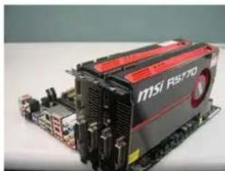
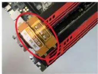
Step 2. Connect two Radeon graphics cards by installing a CrossFire Bridge on the CrossFire Bridge Interconnects on the top of the Radeon graphics cards. (The CrossFire Bridge is provided with the graphics card you purchase, not bundled with this motherboard. Please refer to your graphics card vendor for details.)
CrossFire Bridge
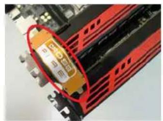
or
Step 3. Connect the DVI monitor cable to the DVI connector on the Radeon graphics card on PCIE2 slot. (You may use the DVI to D-Sub adapter to convert the DVI connector to D-Sub interface, and then connect the D-Sub monitor cable to the DVI to D-Sub adapter.)
English
2.5.2 Driver Installation and Setup
Step 1. Power on your computer and boot into OS.
Step 2. Remove the AMD driver if you have any VGA driver installed in your system.

Please check AMD website for AMD driver updates.
Step 3. Install the required drivers to your system.
For Windows
XP OS:
A. AMD recommends Windows
XP Service Pack 2 or higher to be
installed (If you have Windows XP Service Pack 2 or higher installed in your system, there is no need to download it again):
http://www.microsoft.com/windowsxp/sp2/default.mspx
B. You must have Microsoft .NET Framework installed prior to downloading and installing the CATALYST Control Center. Please check Microsoft website for details.
For WndvistaTM OS:
Install the CATALYST Control Center. Please check AMD website for details.
Step 4. Restart your computer.
Step 5. Install the VGA card drivers to your system, and restart your computer. Then you will find "ATI Catalyst Control Center" on your Windows taskbar.

ATI Catalyst Control Center
Step 6. Double-click "ATI Catalyst Control Center". Click "View", select "CrossFireXTM", and then check the item "Enable CrossFireXTM". Select "2 GPUs" and click "Apply" (if you install two Radeon graphics cards).
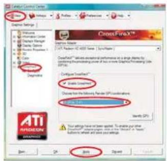

If you have selected the option "Enable CrossFire ^TM ,the CrossFire X^TM function may not work actually. Your computer will automatically reboot. After restarting your computer, please confirm whether the option "Enable CrossFire ^TM " in "ATI Catalyst Control Center" is selected or not; if not, please select it again, and then you are able to enjoy the benefit of CrossFire X^TM feature.
Step 7. You can freely enjoy the benefit of CrossFireX™ or Quad CrossFireX™ feature.
- CrossFireX™ appearing here is a registered trademark of AMD Technologies Inc., and is used only for identification or explanation and to the owners' benefit, without intent to infringe.
- For further information of AMD CrossFireX™ technology, please check AMD website for updates and details.
2.6 Surround Display Feature
This motherboard supports Surround Display upgrade. With the external add-on PCI Express VGA cards, you can easily enjoy the benefits of Surround Display feature. For the detailed instruction, please refer to the document at the following path in the Support CD:
Surround Display Information
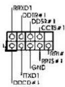
2.7 ASRock Smart Remote Installation Guide
ASRock Smart Remote is only used for ASRock motherboard with CIR header. Please refer to below procedures for the quick installation and usage of ASRock Smart Remote.
Step1. Find the CIR header located next to the USB 2.0 header on ASRock motherboard.
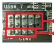
USB 2.0 header (9-pin, black)
CIR header (4-pin, gray)
Step2. Connect the front USB cable to the USB 2.0 header (as below, pin 1-5) and the CIR header. Please make sure the wire assignments and the pin assignments are matched correctly.
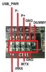
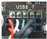
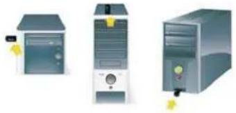
Step3. Install Multi-Angle CIR Receiver to the front USB port.
Step4. Boot up your system. Press or to enter BIOS Setup Utility. Make sure the option "CIR Controller" is setting at [Enabled].
(Advanced -> Super IO Configuration -> CIR Controller -> [Enabled])

If you cannot find this option, please shut down your system and install Multi-Angle CIR Receiver to the other front USB port then try again.
Step5. Enter Windows. Execute ASRock support CD and install CIR Driver. (It is listed at the bottom of driver list.)
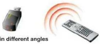
3 CIR sensors in different angles

- Only one of the front USB port can support CIR function. When the CIR function is enabled, the other port will remain USB function.
- Multi-Angle CIR Receiver is used for front USB only. Please do not use the rear USB bracket to connect it on the rear panel. Multi-Angle CIR Receiver can receive the multi-direction infrared signals (top, down and front), which is compatible with most of the chassis on the market.
-
The Multi-Angle CIR Receiver does not support Hot-Plug function. Please install it before you boot the system.
-
ASRock Smart Remote is only supported by some of ASRock motherboards. Please refer to ASRock website for the motherboard support list: http://www.asrock.com
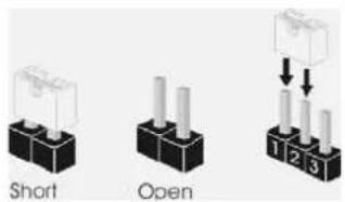
2.8 Jumpers Setup
The illustration shows how jumpers are setup. When the jumper cap is placed on pins, the jumper is "Short". If no jumper cap is placed on pins, the jumper is "Open". The illustration shows a 3-pin jumper whose pin1 and pin2 are "Short" when jumper cap is placed on these 2 pins.

Jumper
Clear CMOS Jumper
(CLRCMOS1)
(see p.2, No. 16)
Setting


Clear CMOSDefault
Description
Note: CLRCMOS1 allows you to clear the data in CMOS. To clear and reset the system parameters to default setup, please turn off the computer and unplug
the power cord from the power supply. After waiting for 15 seconds, use a jumper cap to short pin2 and pin3 on CLRCMOS1 for 5 seconds. However, please do not clear the CMOS right after you update the BIOS. If you need to clear the CMOS when you just finish updating the BIOS, you must boot up the system first, and then shut it down before you do the clear-CMOS action. Please be noted that the password, date, time, user default profile, 1394 GUID and MAC address will be cleared only if the CMOS battery is removed.
2.9 Onboard Headers and Connectors

Onboard headers and connectors are NOT jumpers. Do NOT place jumper caps over these headers and connectors. Placing jumper caps over the headers and connectors will cause permanent damage of the motherboard!
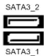
Serial ATA3 Connectors These six Serial ATA3
(SATA3_1: see p.2, No. 18) (SATA3) connectors support
(SATA3_2: see p.2, No. 17) SATA data cables for internal
(SATA3_3: see p.2, No. 13) storage devices The current
(SATA3_4: see p.2, No. 12) SATA3 interface allows up to
(SATA3_5: see p.2, No. 10) 6.0 Gb/s data transfer rate.
(SATA3_6: see p.2, No. 11)
Serial ATA (SATA) Either end of the SATA data Data Cable cable can be connected to the (Optional) SATA / SATAII / SATA3 hard disk or the SATA3 connector on
this
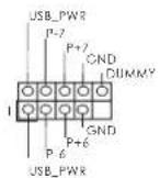
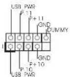
USB 2.0 Headers Besides six default USB 2.0
(9-pin USB_6_7) ports on the I/O panel; there
(see p.2 No. 23) are three USB 2.0 headers on this motherboard. Each USB
header can support two USB
USB_PWD
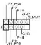
(9-pin USB_8_9) (see p.2 No.25)
(9-pin USB_10_11) (see p.2 No. 26)
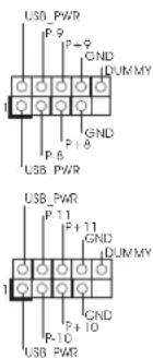
2.0

(5-pin IR1)
(see p.2 No.27)
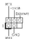
This header supports an
optional wireless transmitting
and receiving infrared module.
(4-pin CIR1) connect the remote
(see p.2 No. 24)
controller
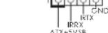
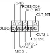
(9-pin HDAUDIO1) panel audio cable that allows
(see p.2 No. 30) convenient connection and
control of audio devices.

-
High Definition Audio supports Jack Sensing, but the panel wire on the chassis must support HDA to function correctly. Please follow the instruction in our manual and chassis manual to install your system.
-
If you use AC'97 audio panel, please install it to the front panel audio header as below:
A. Connect Mic_IN (MIC) to MIC2_L
B. Connect Audio_R (RIN) to OUT2_R and Audio_L (LIN) to OUT2_L.
C. Connect Ground (GND) to Ground (GND).
D. MIC_RET and OUT_RET are for HD audio panel only. You don't need to connect them for AC'97 audio panel.
E. To activate the front mic.
For Windows XP/XP 64-bit OS:
Select "Mixer". Select "Recorder". Then click "FrontMic".
For Windows 7/764-bit/VistaVista64-bit OS:
Go to the "FrontMic" Tab in the Realtek Control panel. Adjust
"Recording Volume".
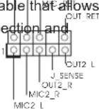
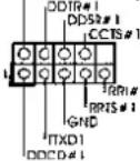
(9-pin PANEL1) several system front panel
(see p.2 No. 22)
functions.

Connect the power switch, reset switch and system status indicator
on the chassis to this header according to the pin assignments below.
Note the positive and negative pins before connecting the cables.
PWRBTN (Power Switch):
Connect to the power switch on the chassis front panel. You may configure the way to turn off your system using the power switch.
RESET (Reset Switch):
Connect to the reset switch on the chassis front panel. Press the reset switch to restart the computer if the computer freezes and fails to perform a normal restart.
PLED (System Power LED):
Connect to the power status indicator on the chassis front panel. The LED is on when the system is operating. The LED keeps blinking when the sys-tem is in S1 sleep state. The LED is off when the system is in S3/S4 sleep state or powered off (S5).
HDLED (Hard Drive Activity LED):
Connect to the hard drive activity LED on the chassis front panel. The LED is on when the hard drive is reading or writing data.
The front panel design may differ by chassis. A front panel module mainly consists of power switch, reset switch, power LED, hard drive activity LED, speaker and etc. When connecting your chassis front panel module to this header, make sure the wire assignments and the pin assignments are matched correctly.
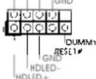
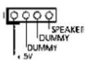
Chassis Speaker Header Please connect the chassis
(4-pin SPEAKER 1) speaker to this header
(see p.2 No. 20)
Power LED Header Please connect the chassis
(3-pin PLED1) power LED to this header to
(see p.2 No.19) indicate system power status.
The LED is on when the system
is operating. The LED keeps
blinking in S1 state. The LED is
off in S3/S4 state or S5 state
(power
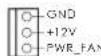
Chassis and Power Fan Connectors Please connect the fan cables
(4-pin CHA_FAN1) to the fan connectors and
(see p.2 No. 37) match the black wire to the
FAN.SPEED.CONTROU
ground
(3-pin CHA_FAN2)
(see p.2 No. 21)
(3-pin PWR_FAN1)
(see p.2 No.9)

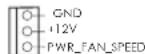
off).

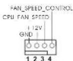
CPU Fan Connectors Please connect the CPU fan
(4-pin CPU_FAN1) cable to the connection and
(see p.2 No. 5) match the black wire to the

ground
pin.

Though this motherboard provides 4-Pin CPU fan (Quiet Fan) support, the 3-Pin
CPU fan still can work successfully even without the fan speed control function. If you plan to connect the 3-Pin CPU fan to the CPU fan connector on this motherboard, please connect it to Pin 1-3.
Pin 1-3 Connected
3-Pin Fan Installation
(3-pinCPU_FAN2)
(see p.2 No.4)

U FAN SPEED
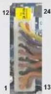
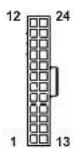
ATX Power Connector Please connect an ATX power
(24-pinATXPWR1) supply to this connector.
(see p.2 No.8)
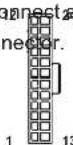

Though this motherboard provides 24-pin ATX power connector, it can still work if you adopt a traditional 20-pin ATX power supply.
To use the 20-pin ATX power supply, please plug your power supply along with Pin 1 and Pin 13.
20-Pin ATX Power Supply Installation
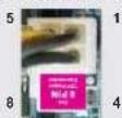
ATX 12V Power Connector Please connect an ATX 12V
(8-pin ATX12V1) power supply to this connector.
(see p.2 No.1)
8 4

Though this motherboard provides 8-pin ATX 12V power connector, it can still work
if you adopt a traditional 4-pin ATX 12V power supply. To use the 4-pin ATX power supply, please plug your power supply along with Pin 1 and Pin 5.
4-Pin ATX 12V Power Supply Installation
Serial port Header
(9-pin COM1)
(see p.2 No.28)
This COM1header supports a
serial port module.
HDMI_SPDIF Header HDMI_SPDIF header, providing
(2-pin HDMI_SPDIF1) SPDIF audio output to HDMI
(see p.2 No. 29) VGA card, allows the system to
connect HDMI Digital TV/
projector/LCD devices. Please
connect the HDMI_SPDIF
connector of HDMI VGA card to
this
header.
English
2.10 Driver Installation Guide
To install the drivers to your system, please insert the support CD to your optical drive first. Then, the drivers compatible to your system can be auto-detected and listed on the support CD driver page. Please follow the order from up to bottom side to install those required drivers. Therefore, the drivers you install can work properly.
2.11 Installing Windows 7/7 64-bit / Vista™ / Vista™ 64-bit / XP / XP 64-bit With RAID Functions
If you want to install Windows® 7 / 7 64-bit / Vista™ / Vista™ 64-bit / XP / XP 64-bit on your SATA3 HDDs with RAID functions, please refer to the document at the following path in the Support CD for detailed procedures:
RAID Installation Guide
2.12 Installing Windows 7/7 64-bit / Vista™ / Vista™ 64-bit / XP / XP 64-bit Without RAID Functions
If you want to install Windows® 7 / 7 64-bit / Vista™ / Vista™ 64-bit / XP / XP 64-bit OS on your SATA3 HDDs without RAID functions, please follow below procedures according to the OS you install.
2.12.1 Installing Windows XP / XP 64-bit Without RAID Functions
If you want to install Windows XP / XP 64-bit on your SATA3 HDDs without RAID functions, please follow below steps.
Using SATA3 HDDs without NCQ and Hot Plug functions (IDE mode)
STEP 1: Set up UEFI.
A. Enter UEFI SETUP UTILITY Advanced screen Storage Configuration.
B. Set the "SATA Mode" option to [IDE].
STEP 2: Install Windows XP / XP 64-bit OS on your system.
2.12.2 Installing Windows 7/7 64-bit/Vista™/Vista™ 64-bit Without RAID Functions
If you want to install Windows® 7 / 7 64-bit / Vista™ / Vista™ 64-bit on your SATA3 HDDs without RAID functions, please follow below steps.
Using SATA3 HDDs without NCQ and Hot Plug functions (IDE mode)
STEP 1: Set up UEFI.
A. Enter UEFI SETUP UTILITY Advanced screen Storage Configuration.
B. Set the "SATA Mode" option to [IDE].
STEP 2: Install Windows® 7 / 7 64-bit / Vista™ / Vista™ 64-bit OS on your system.
Using SATA3 HDDs with NCQ and Hot Plug functions (AHCI mode)
STEP 1: Set up UEFI.
A. Enter UEFI SETUP UTILITY Advanced screen Storage Configuration.
B. Set the "SATA Mode" option to [AHCI].
STEP 2: Install Windows® 7 / 7 64-bit / Vista™ / Vista™ 64-bit OS on your system.
2.13 Untied Overclocking Technology
This motherboard supports Untied Overclocking Technology, which means during overclocking, FSB enjoys better margin due to fixed PCI / PCIE buses. Before you enable Untied Overclocking function, please enter "Overclock Mode" option of UEFI setup to set the selection from [Auto] to [Manual]. Therefore, CPU FSB is untied during overclocking, but PCI / PCIE buses are in the fixed mode so that FSB can operate under a more stable overclocking environment.

See refer to the warning on page 7 for the possible overclocking risk. See you apply Untied Overclocking Technology.
The Flash Memory on the motherboard stores BIOS Setup Utility. When you start up the computer, please press or during the Power-On-Self-Test (POST) to enter BIOS Setup utility; otherwise, POST continues with its test routines. If you wish to enter BIOS Setup after POST, please restart the system by pressing + + , or pressing the reset button on the system chassis. The BIOS Setup program is designed to be user-friendly. It is a menu-driven program, which allows you to scroll through its various sub-menus and to select among the predetermined choices. For the detailed information about BIOS Setup, please refer to the User Manual (PDF file) contained in the Support CD.
This motherboard supports various Microsoft® Windows® operating systems: 7 / 7 64-bit / Vista™ / Vista™ 64-bit / XP / XP 64-bit. The Support CD that came with the motherboard contains necessary drivers and useful utilities that will enhance motherboard features. To begin using the Support CD, insert the CD into your CD-ROM drive. It will display the Main Menu automatically if "AUTORUN" is enabled in your computer. If the Main Menu does not appear automatically, locate and double-click on the file "ASSETUP.EXE" from the BIN folder in the Support CD to display the menus.
1. Einführung
ASRock-Website: http://www.asrock.com/Feature/AppCharger/index.asp
ASRock-Website: http://www.asrock.com/Feature/SmartView/index.asp
(CLRCMOS1,3-Pin Jumper)
(siche S.2, No. 16)
12

Default-
Einstellung
23

CMOS
loschen
www.asrock.com/support/index.asp
Site web ASRock: http://www.asrock.com/Feature/AppCharger/index.asp
Site web ASRock: http://www.asrock.com/Feature/SmartView/index.asp
www.asrock.com/support/index.asp
(ATX Form Factor: 12.0-in x 8.2-in, 30.5 cm x 20.8 cm)
(ASRock Extreme Tuning Utility)
Sito ASRock: http://www.asrock.com
Sito ASRock: http://www.asrock.com/Feature/AppCharger/index.asp
Sito ASRock: http://www.asrock.com/Feature/SmartView/index.asp
7/7 64-bit/VistaTM/VistaTM 64-bit:
(8-pin ATX12v1) 12 V a quoi connetiore.
(vedi p.2 Nr.1)

www.asrock.com/support/index.asp
Siteio web de ASRock: http://www.asrock.com/Feature/AppCharger/index.asp
1xI/OUHTpynnBbOda/BbBOda

ASRock Hanomuhaem...
Дя obecneeyma MaksmaBhoN npon3BodnteBHOCTN OC Windows7/764-bit/Vista™/Vista™ 64-bit pekomehyctcB BIOS bIbpaTb napametpa Storage Configuration (KoHpyaunz 3anomnauoero yctpoctBa) pekIM AHCI. NpOpbHbte CbeDeHnO hactpoKe BIOS cM. B pykoBOdCTBe noJIb3OBaTeHa npinlaeraMOM KOMnKT-DnCKe.
1.2 Cneunphiauin
| Платфорma | - Форм-фальТСТР ATX: 12,0 x 8,2 дюма / 30,5 x 20,8 сM
- Весь Тердь КONDенCatopньй пproekt |
| Празецсор
- FSB 2400 MHz (4.8) | - Празецкa Socket AM3+ поцessорв
- Празецкa Socket AM3 поцessорв: AMD Phenom™ II X6 / X4 / X3 / X2 (he поцessовся 920 / 940) / Athlon II X4 / X3 / X2 / Sempron
- Празецкa востemsьдернып поцessорв
- Празецкa UCC (Unlock CPU Core) (cM. OCTOPOXH0, рункT 1)
- Тхнокугя 4 + 1 Power Phase Design
- Празецкa поцessорв мочистю до 140 BT
- Празецкa тхнокугий AMD Cool 'n' Quiet™
GT/s)
- Празецкa тхнокугий Untied Overclocking
(сM. OCTOPOXH0, рункT 2)
- Празецкa тхнокугий Hyper-Transport 3.0 (HT 3.0) |
| Набор микposхem | - Северный мост: AMD 970
- Кжный мост: AMD SB950 |
| Пам扼ь
- 4 x 퍵зда DDR3 D | - Празецкa тхнокугий Dual Channel DDR3 Memory Technology
(сM. OCTOPOXH0, рункT 3)
IMM
- Празецкite DDR3 2100(OC)/1866(OC)/1800(OC)/1066/800 He-ECC, бezбучерься пам扼ь (сM. OCTOPOXH0, рункT 4)
- Мас. 32 Г (сM. OCTOPOXH0, рункT 5) |
| Гизда - 2 x сnotа
разширения
- 1 x 퍵зда
- 2 x 퍵зда PCI | PCI Express 2.0 x16
(PCIE2: реким x16; PCIE3: реким x4)
PCI Express 2.0 x1
- Празецкыает АMD(CoabRax)FireX |
| Аydюсисема | - 7.1 CH HD Адю HD с Довльно 3ашитои
(Kоading-decodер Адю Realtek ALC892)
- Празецka Premium Blu-ray audio
- Празецka тхнокугий THX TruStudio |
| ЛВС - PCIe x 1 Giga
- Realtek RTL8111E | bit LAN 10/100/1000 Mb/s
- поцesska Wake-On-LAN
- Празецka onpeдения кабеля NBС
- Празецka зерocбераяцшero Иntерфейca Ethernet 802.3az
- Празецka вета symax PXE |
| Разьемы Ввoda-
Бывoda на за干嘛е
паели | I/O Panel
- 1 x поТ мьши PS/2
- 1 x поТ клавиатурь PS/2
- 6 x поТ USB 2.0 на за干嘛е паели в стандарно конфигураци
- 2 x поТ USB 3.0 на за干嘛е паели в стандарно
конфигураци
- РAZьем 1 x RJ-45 LAN cSBetODиODиBIM ИndikatopOM (Иndikatop
katop SPEED) |
| - CoeДиNTeNB 3БУКВОВ ПОДССТeMb: 6БОВОВ KОЛONHа TБИьна
КOLONHа / цENTРальна/ cybbyфер / линneyнь вхoД / поедnia
КOLONHа / МИКрофан (сm. ПЕДУПЕЖDEHNE 6) |
| SATA3 | - 6 x nopTOB SATA3 co ckopocstby nopeDAчу DAньx 6,0 Γбnt/c,
подэржka Функциа RAID (RAID 0, RAID 1, RAID 5 n RAID 10), NCQ,
AHCI i «cropчero полкlioчесу» |
| USB 3.0 | - 2 x заднix поTRA USB 3.0 на КОНтоглесе Etron EJ168A c
подэржков Interpфсев CS USB 1.0/2.0/3.0 и сkopости поедчу
даных до 5 Γбnt/c |
| Колдки - 6 x
платe | разьема SATA3 6,0 Γбnt/c
- 1 x Kolondka Инфраркасно моулья
- 1 x Датчik поьзоватьскои Инфраркасно моулья
-
1 x
1 x
1 x
- 1 x
- 1 x
- 1 x
- 2 x coeДиNTeNB CPU FAN (1 x 4-KONTAKTHь, 1 x 3-KONTAKTHь)
- 2 x coeДиNTeNB Chassis FAN (1 x 4-KONTAKTHь, 1 x 3-KONTAKTHь)
- 1 x coeДиNTeNB Power FAN (3-KONTAKTHь)
- 24-KONTAKTHь Kolondka петаня ATX
- 8-KONTAKTHь PaSZbem ATX 12 B
- Адиротаьсв поедим панели
- 3 x Kolondka USB 2.0 (ODHa Kolondka对于我们 nopeDEXKn 6
dОпОнNTeNBых поюв USB 2.0 |
| BIOS | - 32Mb AMI UEFI Legal BIOS c подэржков rpaФчeckoro Интэрфс�а
поьь зовать
-
нодэржka "Plug and Play"
- ACPI 1.1, вклочени lo соб'tьгм
- подэржka ржима настroyки бezп поедьчek
-
нодэржka SMBIOS 2.3.1
- PeruNPovBa Ka npяжени CPU, VCCM, NB, SB |
| Компaktдис
подэржkn | - ДраиВеры, УтINITы, AntINBИрUC (пpoбнay ВERCЯ), Рpoбнay ВERCя
прогамы CyberLink MediaEspresso 6.5, AMD OverDrive™, AMD
Fusion, AMD Fusion Media Explorer, ASRock MAGIX Multimedia Suite
noctabuick |
| Унkaльна
Осobенhoeь | - ASRock Extreme Tuning Utility (AXTU) (сm. OCTOPOXKH, рункT7)
- ASRock Instant Boot
- ASRock Instant Flash (сm. OCTOPOXKH, рункT8)
- ASRock APP Charger (сm. OCTOPOXKH, рункT9)
- ASRock SmartView (сm. OCTOPOXKH, рункT10)
- ASRock XFast USB (сm. OCTOPOXKH, рункT11)
- ASRock XFast LAN (сm. OCTOPOXKH, рункT12)
- ASRock XFast RAM (сm. OCTOPOXKH, рункT13)
- ASRock Crashless BIOS (сm. OCTOPOXKH, рункT14)
line Management Guard)
(сm. OCTOPOXKH, рункT15)
- ASRock Internet Flash (сm. OCTOPOXKH, рункT16)
- Т电商OTOMA ASROK дд ВСпрпЗВЕдENЯ 3БУКВКИЧЕНOM I
ВыклочenvHom COCTORYN (сm. OCTOPOXKH, рункT17) |
| - Hybrid Booster: | - пьавная有很大 поюка чASTOTы有很大 поц ECCOPa
(CM. OCTOPOXHO, nyнкT 18)
- ASRock U-COP (CM. OCTOPOXHO, nyнкT 19)
- 3aцида OT сбов загузки Boot Failure Guard (B.F.G)
Turbo UCC |
| Коныпь
оборUDовеня | - Датчни ТЕмпературь有很大 поц ECCOPa
- Датчни ТЕмпературь有很大 поцуca
- TaxOMeТрь ВЕNTINЯТОВ CPU/Chassis/Power FAN
- БecшUMнь ВЕNTINЯТОР LП/cnstemHoro有很大 noka
- МульTGИКонтPORь SCOPOSTN BЕNTINЯТОРа有很大 noI/шAccn
- Конырь = наразжени; +12V, +5V, +3.3V, Vcore |
| Операон | - СOBМecTIMOCb c Microsoft® Windows® 7 / 7 64-bit / VistaTM / Пдемжka 64-pazdnoй верси VistaTM / XP / XP 64-bit (CM. OCTOPOXHO, nyнкT 20) |
| Ные - FCC, CE, WHQL
СИСТЕМы
СергИФКату | - СOBМecTIMOCb c ErP/EuP Ready (ТpeбуETСь有很大 поц有很大 noTANH
СOBМecTIMb c ErP/EuP) (CM. OCTOPOXHO, nyнкT 21) |
*DnIeTalbHoi INΦopMaunn npOdykTa, noKanyNCTa nocTe Hau Be6caiT: http://www.asrock.com
BHIMAHHE
CnEduT NoHMaTb, TcO OBePKIOKINrOM CBA3AH ONpeJeENHHI pNCK BO BCeX CnyAax, BKNIOUaY I3MeHeHne yCTAHOBK BIOS, PpIMeHHe NteXHOrM Untied Overclocking nnNCIOB3OBAHme INCHPTyPmEtOB OBePKIOKINrA CTOPHNIX npOn3BOJNTenE. OBePKIOKINrMOKeT NOBNIATb HA CTABINbHOCt bpaObTI CNCTeMb I DaJIe Bb3BaTb NOBpeKDeHne BXoJxN X He KOMNoHEnTOB N UCTPOJCTB. PInCTynar K OBePKIOKINrHY, Bbl NnHOCTbO6epTe Ha c68 BCE CBA3aHHbIe C Hm PNCKN pACxoDbI. Ml He 6yEm HectnOTBETCBHNOCTb 3a IIObIe BO3MOXhIIe NOBpeJDeHn B peyIbTaTE OBePKIOKINrHa.
OCTOPOXHO!
1.ФункцASROCKUCC(UnlockCPUCore)ДаeTpa36nokpOBy npocccopOB AMD npocTo.ПрпnomoиpepeknHuaTeNlUnlock CPU CoreBUEFIbMoXeTe pa36nokpoBaTbdoonHInTeNbHeярИн HacnaJdaTcB6ecnntbHbIMyBEnuHEmnpOn3BOInTeHbOCTn!PpN BkIOueHHU UCCBcnyaeCdBy- INTrepxaepbHMnpoceccopAMOn ppeBaTATCBYtbpexAdepHbIe.YHEKOTbIXHTbipExaepbHexMOdeNe MoxHOpa36nokpoBaTbdoonHInTeNbHyIO KsI-NamrTB L3(do6MaaIT). PoxKanyIcTA,yHTnte,YTOФyHKZUAAUCNoDpeKINBaETcTOnbKOprnp paBoTe c npocccopAm AMD DnS Socket AM3/AM3+.PpImeHaHne:He kaxdbI npocccop 6ydet CTaBnHo paobTaB noCte pa36nokpOBKn, CKpbTBeIqPaMOrTpa0oTaB HekoppeKTHO.
2. DnHnA CNTeMHnA PIIATA NOIDepKnBaET TexHoNOrIO pa3dEhHO rpa3roHa (NoBbIeHnA YAcTObTb CNTeMHoN UINHb). NoDpObHbIe CBeDeHnC M.B pa3dJe E《TexHOnrna Pa3dEhBO rpa3roHa》Ha cTp.29.
3. DaaHaa MaTeepnHcka nnata noDdepeKnaBaetTexHONrIO DbyXKaHaNbHO namrtn Dual Channel Memory Technology. Npeed ee nCOnb3oBaHem He 3abYbTe npOHTaB HCTpykUIN NO npabunbHO YCTAHOBKe MOnyIe namrtn B pykoBODCTBE no yCTAHOBKe (cTp.13).
4. Pndepkka qactotb namr 2100/1866/1800/1600 Mf3abnnt ot nnonb3yemoro npouecoppa cpa3bemom AM3/AM3+.Дя nnonb3oBaHnMoDyIra naTn DDR3 2100/1866/1800/1600 Ha 3toMATEPHCKOIIaTe O3HaKOMBtEcB coNtckOM noDpeKJBMaEBix MOyIe NAmr HHaAeMe Be6-caiTe, 4To6bl Bb5paTb COBmctnMbte MoyIi NAmr. He B pexIme OePknKhrna narnr DDR3 1866 noDpeKXBAeTc LlAM3+.
Be6-cainr ASRock http://www.asrock.com
- B ciny orpaHueHnonepaHIOHHcHCTeMbI paKHTeCKa EMKoCTb nAMrTMOKeT6bIT MehBSe 4R6 dNl oBeCneHnpe3epBHO rMeCTa dNl HcNtOBaHn CnCTeMoW Windows7/VistaXP.Taknx orpaHueHn Het dNl WindowsOS c64-bit CEHTpAebHbIM npoueccopom. TexHONrHA sRock XFast RAM nomoraet nCnObOaB Ta mRaTb, KOTopar He nCnonbayetc OC Windows
- NopdepkmbaetcpaobTa MmKpOHHoB BxOda BpeKmMax MoHO n Ctepeo. NopdeepkmbaiocTc2-4-, 6-8-kaHaHbHbI peKmbblbBaOda3Byka. COOTBETCTBYIOUne CXemblnoKnIOueHnONCAHbHa ctp.3.
- Cnyke6hna nporpamma ASRock Extreme Tuning Utility (AXTU) -3to yHnBepcAibHoe cpeCTBO ToKoH NactpOKn pa3NHybIX fynKuN CnCTembl cyD6hIM IN NOHTbIM INTEPceEICOM, BKJIOHaQaIpa pa3dJIbI Hardware Monitor (HaBIOJeHne 3a o6OpyOBaHNEM). Fan Control (YnpabNeHne BENTIaTOpOM). Overclocking (Pa3roH) npouecCopa), OC DNA (IapametpbI «pa3roHa) and IES (ABTomAtueckoe 3heproc6peXeHne). B pa3dene Hardware Monitor (HaBIOJeHne 3a o6OpyOBaHNEM) OTObpaKaOTcN ochOBhie xapaKTePcTmKn annapaTHbIX cpeCTB CnCTembl. B pa3dene Fan Control (YnpabNeHne BENTIaTOpOM) OTObpaKaETcCKopocTB BENTINATOPa n TemnepaTpya, KOTOpble MoxHO perynipobat. B pa3dene Overclocking
(«Pa3roH» npoeccopa) moKHO yBENmHTb pa6OHy qactoty LNY, yTO6bl OOBtCBs ONIMALBOH NPOIN3BOIDNTeNBHOCTn CInCTEmb. B paoIe OC DNA (IpaAMTpbl «Pa3roHa») MOXHO coxpAHITb HAcTpoIKN «Pa3roHa» npoecoppa B INDE npOPhJRA, KOTOpB NOTOM MOXHO npeINOXHTb Dn IcONb3OBAHN CBOHM dpy3bM. Dpy3b CMORY T aRpy3NTb npOphIN b
«Pa3roHa» Ha CBOH KOMNBoTEpBl NOnyHTB anAIONuHb peSyIbTa. B pa3dene IES (ABTomATHeCKoe 3HePrc6BepeKeHHe) MOXHO HAcTPOITb perYrTOp HAnpReEHHaTak, YTO OH bEyET yMeHBsATb KOnHcTeBO paOtaHux JINH NITAHNA, YTO6bl NODHbK TND cInCTEmbl Be3 uepBa dn ee npOIN3BOIDNTeNBHOCTNo B VpemnpocToAep LNY. YTO6bl y3HaB, Ka paOToBc c nporpAmMo ASRock Extreme Tuning Utility (AXTU), nocetnte haW caRb INHTepHete. Adpec caiTa ASRock: http://www.asrock.com
-
ASRock Instant Flash - nporpammaДЯnpuINBKNBIOS, BCTpoEHnAB Flash ROM.Данhoe cpeCTBOДЯOBHnEHNBAIOS yMeet pa6oTaB 6e3 BXOa B O npaUNHOHbIE CNTEMB, BPODE MS-DOS nIN Windows* TTo6b3anyCTNB nporpAMMy DOcTaTOHn HaxaTb F6> BO Bpemr camOTecTIPOBAAHNA CNTEMB (POST) ININ BOITB BIOS pni NOMOUI KhoNkN F2> IN Bb6paTb NYKT ASRock Instant Flash cheep MeHIO. 3anyCTNE nporpAMMy n COxPAHTE HOBBI BIOS Ha USB-ФN3Kny, DICKETY INN JECTKM DICK. Nocne 3TORO Bbl CMOXeTe ONPaTMBHO 0bHOBtB BIOS, 6e3 Heo6XOnMOCTN NOJROTBKn DOONHHTeBHON DICKETb, 6e3 YCTAHOBKN nporpAMMbI npoUINBKN. IMeHTe B BVNDy, YTO USB-ФN3Wka INN BHHecTeP DoJIKHb IHCNOJb3ObA Tb faINOBYIO CNTTEMY FAT32/16/12.
-
Ecln BbXOTNE 6bCTpee n 63 orpaHnueHn 3apKaTb cBOn yctpoCTBa Apple, HanpImep iPhone, iPod u i iPad Touch, kOmnaHn ASRock npiroTOBnA OTNIHNOpe peHne nIa BAC-ASRock APP Charger. IpocTo yCTaHOVB dpaBep APP Charger, BcI cmOKeTe 3apKaTb IPhone ot KOMNbIOpTa HAMHOro 6bCTpee, ycKopHe ncoCTaBHT do 40% .ASRock APP Charger no3BOJnEET bCtpo 3apKaTb HeCKONJIbKO yCTpoCTB Apple OndHOBPeMeHNo I daKe noNDepKmBAet HEnpepbIBHyO 3apKy, KorDa KOMNbIOpTe nepExoNT B pEKMM OxUdAnHn (S1), pEKMM OxUdAnHn C coxpaHeHnEM DaHHbIX B O3Y (S3), pEKMM rIbepHaun (S4) mI IN pEKMM BkKnOChEHN (S5). YCTaHOVB dpaiBep APP Charger, Bbl NCbIbTaete He6bIbAloe yDObCTBO 3apKn.
Be6-cain ASRock: http://www.asrock.com/Feature/AppCharger/index.asp
- SmartView - 3to INTELEKTYaIbHa cTApTOBa cTpaHua dIe 6pay3epa IE, HA KOTOPO OTobpaxaIOCT HAnbOone NoceUaEMbIe Be6-cAITbI, NCTOpNIOseUeHH, Dpy3bB FAcBeoKBIOBnEMLbIe NtOKM HOBOcTei. 3Ta HOBAIyHKUNI OBeCneuBAET BoJe yDObHoe IcNOnb3OBaHHe BO3MOXHOCTe INHTepHeta.CNTeMHbIe NIIaTbI ASRock 3KCKIO3INHO ChabkaIOr cnporpAMMo SmartView, nomarokuee noNDepkmbaTB CB8c dpy3bMa. Iporpamma SmartView paBotaert BOC Windows7/7, 64-pa3paHnaB Bepcra/VistaTMVistaTM, 64-pa3paHnaB Bepcra n 6pay3pe IE8.Beb-caIT ASROck: http://www.asrock.com/Feature/SmartView/index.asp
11.Фуннлг ASRock XFast USB yBENHBAeT ckopocTB pa60bI ycTpoiCTB USB.PoCt ckopocTN 3aBNCIT OYcTPOiCTBa.
12. ASRock XFast LAN obeceneHbAe 60one 6bIcTpbI DocTyK cTeIN HTEpHeT, KOTOpB I daCT OINCAHNbIe dAnee npEnMyIeCTBa. YctAHOBKa npInOpNTetOB npInOKeHn IIBC: MoKHO 3aDaTb ONTIMaNbHbI npInOpNTET DnB CBOero npInOKeHn N/IN Do6aBntb HOBIE npOrpaMMbI. BoJeE Hn3Ka JATEHTHOCTb B Irpe: IocLe yCTaHOBKn 60one BbICOKO npInOpNTeTA Irpe B pExnme OHJaiH, MOKET CHN3ITbC JaTEHTHOCTb B Irpe. FOpMnPOBaHne TpaФnka: MOXHO OJHOBPeMeHNO IpOCMAtpINBaTB BIDeo BbcOKO pa3peSeHnHa Youtube IN 3aRpyKaTb faJIbI. AhJIIN DaHHBX B peaJIbHOM BpeMeHn: B OKHe COCTOHRM MoXHO JERKO ONPeDEJIbT, KaKHe NOTOKN daHHBX IpeJaOTcB DAHHB MOMEHT BpeMeHn.
13. ASRock XFast RAM - HOBARФункць, BXOДAZA B COCTAB YTNINTB ASRock Extreme Tuning Utility (AXTU).Благогдя eH,ИнгльзуETcR O6nactb namTn, INIbI30BAnHe KOTOpH He BO3MOxH Ho npoUeCCope c 32-6nTHoN OC WindowsASRock XFast RAM cokpaauet Bpem 3aqrpy3kn NCTOpnNoceSeHHBe6-caITOB,CyueCTBeHHO yckopraHaHBnTaUIO No ceTINHTepHET.KPome TOrO, COKoPCt b pa6ToB Adobe Photoshop 5 ybeJIuHBAeTcB B PnTb pa3.B Yncne npemMyucTe ASRock XFast RAM - cokpaauHHe qACToTb obpaueHm K SSD-hakOnITeYm I KeCTKIM DnCKAM n IpOJNeHec Cpoka HX ekCnPyatauH.
14. ASRock Crashless BIOS no3BONNAET noIb30BATENMAOBnTBIOS, He 6oRc b OKa3a.B cnyae otKIOUeHNE 3neKTPO3HePRn B npOceCE OBHOBHeHRAI BIOS ASRock Crashless BIOS aTOMATnueckn 3abePnaet npOeDpyo 6HOBHeHRAI BIOS nocne BO3oHOBHeHnnoaun 3HePRn. ObpaITte BHIMAHHe Ha To, YTo BIOS pa3MeuaetcB KOpHEbOM KaTanoRe BaWero USB dncka.DaHHa FyHKnI DAocTyHa TOnbKO DnnpotOB USB2.0.
15.CnmoBIOOMG aMmHnCTpaTOpbI Moryt yctaHaBnBaT bacblncnoB3oBAHnIHTepHeta nIN ORpaHmNbaTB K Hemy DoCTyn B yka3aHHoeBpEM.BblcmOKeTe COCTABnTb rpaFkn NaHauNa NOKOHAHn DOCTyNAKHTepHety dnyDpynx NOB3OBaTeNe.IrTaToro, YTO6bI NOB3OBaTeInHe CMOrnn OboHn OMG,B roCTeBbX yueTHbX 3aNNcX OTCytCTBye ONuHN3MeHeHn CnCTemHOrO BpeMeHn.
16. Internet Flash ocyuieCTBnreT nock DocTynhbix 06HOBLeHn npoWnBKn UEFI ha hauwx cepBepax. HbIMn CNoBAMn, cnCTema aBTOMaTHueCKn haoDHT noCneHNHe Bercm UEFI ha hauwx cepBepax n BbIOnnHer nepenporpaMMnpoBaHne, He BXoJr B OC Windows. O6paTnte BHMamHe Ha To, YTO AKTNBaUN DaHHO fYHKUIN BO3MOKHa TOnbKO Ha KOMNbIoTePax, HAcTPOeHHbIX KAK DHCP KIneHt.
17. TexHIOIgAASRocIINBOCpOIN3BeDENH3Byka BO BKNIOUeHNOM I BbIKIOHcHOM COCTOAHN N03BOJnEIT NOJIb3OBaTeNIM NOPTaTINBbIX ayINOUCTpOINCTB, TaKHX KAK MP3-IIneepbI INMOBILbHbIe TenePOnbl, IpocNyINBaTb C HNX BbICOKOKaueCTBeHHbI 3Byk ChepeKoMnIBoTeP, DaKe KOJa KOMNbIoTeP BbIKIOHEn (INH HaxOINTCB PexKIMe ACPIS5)! Kpome TorO, K daHHO MATEPHNCKO nnate BeCnPaTHO (DOONHInTeMbHO) npinaraetcayIOKAben b c 3,5-MM WtekepaMn, KOTOpB o6ecneHBAeT
Hain60nee yno6Hoe noKIOHeHne aymoocpOCTB KOMnIbTopey.
- XOra daHHa MaTePHNcKa PnIaTn noDaePKBaET nIaBHyo HAcTpoKy qactoTb, ycTaHabINBaTb NOBbIeHHyIO qACTOTy He peKOMeHNyTeC. NcNoJIb3OBaHne 3NaueHm qactoTb IINHb IPOeCCOPa OTnUHaIOuXcxr O T peKOMeHNDoBAHbIX, MOKET pNBeCTN K HeCTaBnBHO paBOte ChCTEmbI INN NOBpeXeHIno PNOeCCOPa MATEPHNCKO pIaTb.
- PnO6hApUxHEn npePepBa npoueccopa pa6oTa cnTeMbY ABOMATueckn 3aBepuAeTcN.PpeKJe Yem BO306HoBntb pa6oTy CNTeMbY yBeJNTecb B HOpMaJIbHOpa6To BeHTINlTOpa npoueccopa Ha MaTePHNckO pIATE NOTCOEHNHt EHy pNTAHy, a 3aTEM CHOBa NOKnIOHTE erO. Yo6bI IyNHyHtB OTBOD TENJa, He 3a6yIbTe npn C6opKe KOMNbIoTepa HaHeCTn TepMonAcTy MeXy IpouecCopm NpaHaTOpom.
- OC Microsoft Windows XP / XP 64-pa3pndHoi Bepcnei, He noDpeKnaeT ASRock XFast RAM.
21.EuPpacunpboBbAercaKakEnergyUsingProduct.CaHap36bn p3pa6oTahEbponeckmCoO3omnOnpeDeneHHN3hepronTppeBneHHn roTOBbIX CNTem.No Tpe6oBaHnIO EuP CNTema B BblIOHcHOM coCTOBHN HONKa NOTpe6nIbMeHe 1BT3heprn. DncooTBcTBNa CTAndApTy EUP HyKnBuCOoTBcTByOuHme MaTePHNCKaIINaTaN KOnMaHn Intel npednoxna,TO CoMBeCTHMb cEuP6nOK nHTAHn DOJKeH oBeCneHbTa50%3fFekTHBHOCTb INHHN nHTAHN 5V npn Notpe6NeHH 100mA(BpeKmmeOxndAHN).CBepTEc bHFPopMaueH npOn3BOUnteEH 6NOKOB nHTAHN,YTO6bBlb6paTb moEnb cNoDpeKko EuP
Pycckn
1.3 YctaHOBka nepembIeK
KoHnIpyaunna nepembueck nIJIIOCTpnpyetc H a pncuHke. KOrda nepembUka HaedeTa Ha KOHTaKTbl, OHn Ha3bIbaOTcra "aMKHyTbIMn" (short). Ecnn Ha KOHTaTKax nepembUKN HeT, TO OHn Ha3bIbaOTcra "pa3OMKHytbIMn" (open). Ha nIIIOCTpaunn NOKa3aHa 3-KOHTaTHa nepeMbUka, y KOtopoN KOHTaKTbl 1 n 2 3aMKHyTbI.
Nepembyka YctaHObKa
Onncahne
OuTcKa CMOS
(CLRCMOS1,
(cm. crp. 2, n. 16)

CraHapThbIe

OncTcMOS
PpmeaHne.
KoTHAKTHA KONOJKA CLRCMSO1 NO3BOJNERT ONUCTNTb DAHNHIE CMOS.ДЯ ONUCTKN DAHNBIX N BOCTAHOBENHRA 3ABODCKNX CNTEMHbIX NAPAMETPOB CHaYANA BbIKIOUHTe KOMNbIOTeP IN OTCOEINHITE CeTEByKO BNKY Ka6EnI NITAHN O T 3NEKTPOP03ETKN. BbIKNITE He MeHee 15 CEkyND I KOJINaYKOBOI NEPEMbIKHO HA 5 CEkyND NEPEMKHITE WbIPbKn 2 IN 3 KOHTAKTHO KONQDNCLRCMSO1. ODAHKO H npOIM3BOIDNTe ONUCTKY CMOS HENOCPEDCTBEHNO NOCNE OBOHBENHNA BIOS. EcnI He NeO6xOIMO ONUCTNTb CMOS cpa3y JKe NOCNE OKOHANHA OBHOBENHBAIOS,TO, nepei ONUCTKoi CMOS, Heo6xOIMMO Chauana BblONHtB 3ARpy3KY CNTEMbI, a 3aTEM 3ABEPuNTb ee paBOTy. PpIMNTe BO BHIMAHME, YTO napOl, DATA, BPemr, npOpInb NOIb3OBATEHn NO YMOnAHNO, INDEHTNPMKATOp 1394 GUIID n MAC-ADPEC 6dyT OHIIeHb To bko Torda, KOrda 6yDet NsBNeHa Hc CBOero IHe3da 6atapeHKa CMOS.
1.4 KIoJokn npa3beMbHa nIaTe

MHeoIeHa nNaTe KONoKn pa3bEmbHE RBAJOTcR KOHTaAMn dNnpeMbueK. HE YCTAHABINBAIte nepeMbUKN Ha 3TN KNOkNn pa3bEmb-3To npNBedT K HeoBpaTMOMy NOBpeXdHnMo MATEPHCKO nnTa!
Paaemb Serial ATA3
He RaTReTcHaPiPaBJIeHHbIM.
JIOBOHn3ero coeHNHTeNE MoKcT
6bIb NIOKIIOueH NIOK JXeCTKOMy
ncky nHTeppeca SATA3 n6oK
MATEPHNCKOITIATe.
KoIouKa USB 2.0
(9-KOHrakthm USB_6_7)
CM. cTp. 2, n. 23)
IOMMIO WecTb CTaHapTHbIX
nopTOB USB 2.0 Ha nahen BBOda
BbIBOda,Ha DaHHoMaTepuHCKoN
PnTaTe npEyncMoTpeHo Tpu pa3bema
USB
noepxnae Ta nopa USB 2.0.
(9-KoHTaKTHbMb USB_8_9)
(cm. cTp. 2, n. 25)
(9-KOHrakThbUI USB_10_11)
(cm, ctp. 2, n. 26)
KoIodka INΦpaKpaChoro Moyn
(5-KOTAKTHBIMR1)NOKNIQUHTBDOONIHHTB
(cm.cTp.2,n.27)
HHppakpachoro
npneonepeadaTnka.
DaHHa KOnOJaKa No3BOnJaTe
MouyIb 6ecnpoBaoHoro
DatukNONb3OBaTeJIbCKOrIOHΦpaKpaChORoMoUyIa
(4-KoHTaKTHbI CIR1)
(cM. cTp. 2, n. 24) npMeMHNK.

DaTnKMOXHOHCIOB3OBaTBnA
NIOKNIOUHeHnI DcTaNIOHHbI
Aynopa3bEm nepeednei
naHeJI nnI npncOeHHeHn
(9-KOHTaKTHbHdAudIO1)
(cm. ctp. 2, n. 30) obecneuBaK
ynpaBneHHe IMM.
3TOT INHTeppeic npedHa3NaueH
aynokabena nepedne nahein,
IOJKNIOUChHeAaIIOOyCTPOiCTB

1.Cntema High Definition Audio noDnepKmBaet yHKnio
abTomatnueckoro 6hapuykeHnpa3bemOB (Jack Sensing), oHaiko
Ie ee npabnbo npoBt Kaebnb NaHm B KOPNvce DonKeH
noDepkmbHDA.PnC6bpeCNCTeMbCneJeHTNCHPTyKmH
PnBHeHbIM B HaaEM pyKOBOCTBE INyPOBOCTBE NIOb3ObaTeJIa
Дя Коруca.
- EcnBbIncnoJIb3yTe aynonaneHb AC'97, noKnIOHTe ee K KOJNOKe
ayINHTepeeca nepedne paheu nceyUOIM 06pa3oM
A. PódklouchTe
BbBOdbI Mic_IN (MIC) K KOHTaKTam MIC2_L
B. NpoknouTe BbIbObl Audio_R (RIN) K KOHTaKtAm OUT2_R, a
BbIOBbI Audio L (LIN) K KOHTaKTaM OUT2_L
C.Подкнчite Bыбовс Ground (GND) K KOHTaKТam Ground (GND).
D. KOthaktbMIC_RET n OUT_RET npedha3HaHeHb ToIbko dIa
aydnohaHn HD. Pn nncno3oBAHN aydnohaHn AC'97
NIOJKNIOUaTb INx HE HxHNO.
E.ПpoeDypaakTnBaunMknpOfoHa npBedeHa Hnke.
DnAOCWindows
XP/XP 64-6nTa
PWRBTN (KhONKa nHTaHn):
IopKnIOUHTe K 3TMM KOHTAKTM KHONKY NITAHNHa NEpeDHeN NaHEnKOPnYCa.Cnocob BbIKHOUYEHNCACTEmblc NOMOUsBO KHONKNITaHNNMOxHO HAcTPONTb.
RESET (KhoNka c6poca):
IopKIOHnTE K 3Tm KOHTaKtAM KONkY cbpOca Ha nepeHne nnaHEn KOpnyca. HaxMITE KONkY cbpOca dnn nepe3arpy3kn KOMNbIoTepa,ecn KOMNbIoTePc «3aBnC» H HopMaIbHyIO nepe3arpy3Ky BbINOInHb He ydaetc.
PLED (HdNkAtoP nTaHHn CnCTeMbI):
IopKnIOHHTe K3TUM KOHTaM INHINKATOp COCTOHN HnTaHnHa
IpeHe nnaHEn KpNpyCa. 3TOT INHINKATOp CBETnCER, KOrDa CNTema
pa6oTaet. INHINKATOp MInraEt, KOrDa CNCTema HaxODITcB pexIMe
OXINDAHnS1. 3TOT INHINKATOp He CBETnCER, KOrDa CNCTema HAXODITcB
BPexIMe OXINADHnS3 INJN S4, NINO BbIKIOHe (S5).
HDLED (HdkaTop akTbHocT JecTeKOrO dNcKa):
IIOKINOHHTe K3TNMOKTaTAMHINIKAToP aKTHBHOCTN JECTKORO DnCKaHa nepeHne naHenn KOpnyca.3ToHINIKaToP CBETNCr, KOrdaOCyueCTBnRETCaCtTBbAHne HIN 3aNNCb DaHHbX Ha JECTKOM DNCKe.
KoHCTpykUaIpepeDneI naHEn MoKeT pa3NmUaTcB C 3aBNCIMOCnOT KOpnyca. Moynb pepeDne I naHEn B OCHOBOM COCTOnI 3 KNONK nITAHN, KHONK c6pOca, INdNKATopa nITAHN, INdNKATopa AKTNIBHOCTn JEcTKoro DnCKA, DnHAMKa N T.I. PIn NOdKNIOeHN K 3OTMy pa3bemy MOyI nepeDne I naHEn KOpnyCa yOCTObepbTeC, YTO npBODa IOKnIOVAOTCR K COOTBETCTByKUIm KOHTAKTAM.
KoNoKa DnHaMnKa Kopnyca (4-KoHTaKTHbI SPEAKER1) (CM.CTp.2, n.20) KOMbIoTepa
IpoKIOHHTe K3ToI KOIOKe Ka6eBbOTdHaAMnKa HaKOpnyce
pa3bem Power LED (3-KOHtAkhThBn PLED1) (CM, CTP, 2, n, 19)

IIOKIIIOHTe INDIAKATop Power LED K 3TOMy pa3bemy IINr OTObpaKeHHa CTAtyca NITAHNA CNTEmbl.3OTCBETOINoN PNOONKT MIRATB BpeXmE S1.CBETOINoN 6yIDEBbIKIOUeH BPEKIMax S3/S4 INN5S (CCTEMA BbIKIOUeHa).
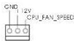
Chassis n Power Fan-coeHnHTen
(4-KoHTaKTHbI CHA_FAN1)
(cm.CTP.2,n.37)
(3-KOHtAHTbH CHA_FAN2)
(cm. crp. 2, n. 21)
(3-KOHtAKTHBIM PWR_FAN1)
(cm. cpr. 2, n. 9)

GND
-12V
-CHA, FAN, SPEED
FAN SPEED CONTROL

GND 12V A,FAN, SPEEC
IIOKNIUOHTe Ka6eINBcHTNITOPa K COeINHNTeRIM N PnCOeINHtE YepHbI WHyP K UStbIp0 3a3eMnEHNA.
Pazem BENTINIATopnpoceccopa
(4-KOHtAKThbI CPU_FAN1)
(cm. ctp. 2, n. 5)
IIOKIOHHTe K 3OTMy pa3bEmy Ka6enB BENTnIaTOpA npOecccopa TAK, YTO6bI ChePbI npoBOd COOTBETCTBOBAN KOHTAKTY 3EMNI.

DaHHa MaTePHNCKaI NaTa NoIepeKbAeB eHTNIrTOpbl npoueccop aC 4-KoHTaKTbHbM pa3bEOM (fYHKUa THXOTo pexIMa BeHTNIrTOpa), ODAHO BHTNIrTObp c 3-KoHTaKTbHbMa pa3bEOM TaKe6 BydyT yCneuHo pa6oTaB, XOTy FynKUa YnpabNEHn CKOpocTBbBpaueHnBA EHTNIrTOpa OKAKETcR HeNoCTyHNO. EcnB bbl XOTMe NOkKnOHITb BEHTNIrTO ppoecoppa C 3-KoHTaKTbHbMa pa3bEOM K pa3bemy BEHTNIrTOp npouecoppa Ha daHHo MaTePHNCKo IINaTe, dIra 3TOrO cNeDuYt NCnONb3OBaTb KOHTaKTb1-3.
KoHTaKbI 1-3 noKnIOueHb YcTaHOBka BeHTnIATOpa C-koHTaKTHbIM pa3beMOM
(3-KOHtakTHbIMCPU_FAN2)
(cM. ctp. 2, n. 4)
KoJokka nItaHnA TAX
(24-KOHtAkhTbHATXPWR1)
(cM. ctp. 2, n. 8)
PoiKIOUHTe K3T0I KOIOKe Ka6bI NITAHINATX.

Hecmptpna To, yTo 3a MaTePHNckA nnata npedyCMtpnBaet 24-7bIpeBo pa3bem nHTAHNA ATX,pa6oTa 6ydtnpOOnKaTcBcra, daxe ecnn aanTnpyTcra TpaDnIOHHbl20-7bIpeBO pa3bem nHTAHNA ATX. Dnncnlo3OBAHNA20-7bIpeBO rpa3bema nHTAHNA ATX BCTABte NCTOCHNkNTAHNA Bmecte co wTekePOM 1 WTekePOM 13.
YcTaHOBKa 20-HTbpeBoro pa3bema nITAHmATX
Pcckn
KoNOKa nHTAHn 12V-ATX (8-KoHTAeTHbI ATX12V1) pa3bemy HeooxOIM (cm. ctp. 2, n. 1)
DOCTaTOUHHyMOUHOCTb
HEBO3MOXHO.
O6paTNTe BHIMAHHe, YTO K 3TOMy
NIOKIOHbBnky6nKa nTahnATX12B,TO6bI ObecneHTb
3nKtpoNTaHINBnPOTNBHOM cnyae BkIIOueHne CnCTeMb6yDet

XoT3a o6bEHNHTeBnA pIATA o6cneHnBaET ATX c 8 SynabKaMn 12V coeHNHTeB Bnactn, 3TO MOKET BCE eue pa6oTaB, ecn Bbl npHHMaete TpaNIOHbI ATX c 4-Pin 12V 3NeKtpOnNTaHne. Yro6bl nCNOBtBb 3NEKTPONTAHne ATX c 4-Pin, noxajnyuCTa BKJIIOHTe Baue 3NeKTPONTAHne Haprady C SynABKO I nPnKpENITE 5.
ATX C 4-Pin 12V UctahOBKa 3neKtponTuHm
KoIoka COM-nopTa (9-KoHTaKTHbI COM1) (cm. cTp. 2, n. 28)
KoJokaHDMI_SPDIF (2-KoHTaKTHbH HMI_SPDIF1) (CM,CTP.2,II.29)
npoeKTopbI IINN KOKpCTaIIneckne naHEnI
pa3bemomHDMI_SPDIF Ha VGA-KapTeHDMI.

DaHnA KOJQKa COM-nOpTa nO3BnRt NOKIQUHTb Moynb nopTa COM.
KonoikaHDMI_SPDIF
0eocneBnaeTnoaHybIXoHoro
ayuOncnHaHaVa VGA-kapTy
HDMI,TONo3BOJraT NoKIOUaTh
KcCTeMe UnppOBeI TeneBnOpaIy
HDMI. CoeHHTe 3Ty KOIOky C
2. Информаць o BIOS
Ytnta hactpoknBIOS(BIOS Setup) xpaHITcB Of nI3u-namrTa H MaATEPHNCKO nIaTe.
TObb BOITN BnporpAMMy hactpoknBIOS Setup, npn 3anyce KOMNIOTEpa HAKMITE F2>
mN BO BPEMa cAmonpoBepKn npn BKNIOeHN NITAHNA (Power-On-Self-Test - POST).
Ecnn 3TOr He CdenA, To npocdupyb TeCTnpoBaHNA POST 6dyT npdoJNaTcB o6bUHBM
obpa3om. Ecnn BBzaxOTnBe B3BaTb BIOS Setup yke nocne POST, nepe3anCTnE cnCTEmy
c nomoBIO knaBnS + + mHaHakTaN KHOKN CBPOCA HA Kopnyce
cnCTEMbl. POnpboHy IO INΦopmaCIO O nporpAMMe BIOS Setup Bn HauDeTe B PyKOBODCTBe
nonb3oBAteTn (B fOpMaTe PDF) Ha KOMnAKT-DnCkne NODePckn.
www.asrock.com/support/index.asp
1.1 Paket icindekiler
ASRock 970 Pro3 Anakart
(ATX Form Faktor: 12,0-inx8,2-inc,30,5cmx20,8cm)
ASRock 970 Pro3 Hizli Takma Kilavuzu
ASRock 970 Pro3 Destek CD'si
2 x Seri ATA (SATA) Veri Kablosu (Istoge Baglu)
1 x G/Panel Kalkani

ASRock Size Sunu Haturlatir...
(CLRCMOS1,3-pinlljumper)
(bkz.s.2 No.16)


Clear CMOSDefault
PLED (Sistem Güci LED'I):
(D: \BIN\ASSETUP.EXE, D: CD-ROM
H
1、はしだに
"Mixer"(半)在记执、续记"Recorder"(L) - “FrontM选报
山
Windows
7/764bit/Vista/Vista64bitOS
の场合:
Realtekコntロルル加5
)夕才開
整末寸。
"FrontMic"(FronntM)
Installing OS on a HDD Larger Than 2TB in AHCI Mode
This motherboard is adopting UEFI BIOS that allows Windows OS to be installed on a large size HDD (>2TB). Please follow below procedure to install the operating system.
- Please make sure to use Windows® Vista™ 64-bit (with SP1 or above) or Windows® 7 64-bit.
- Press or at system POST. Set AHCI Mode in UEFI Setup Utility > Advanced > Storage Configuration > SATA Mode.
- Choose the item "UEFI:xxx" to boot in UEFI Setup Utility > Boot > Boot Option #1. ("xxx" is the device which contains your Windows® installation files. Normally it is an optical drive.) You can also press to launch boot menu at system POST and choose the item "UEFI:xxx" to boot.
- Start Windows® installation.
Installing OS on a HDD Larger Than 2TB in RAID Mode
This motherboard is adopting UEFI BIOS that allows Windows OS to be installed on a large size HDD (>2TB). Please follow below procedure to install the operating system.
- Please make sure to use Windows® Vista™ 64-bit (with SP1 or above) or Windows® 7 64-bit.
- Press or at system POST. Set RAID Mode in UEFI Setup Utility > Advanced > Storage Conf iguration > SATA Mode.
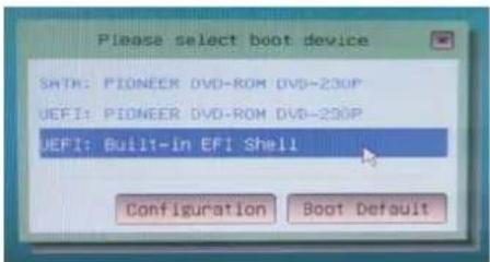
- Choose onboard RAID 3TB+ unlocker > UEFI Mode For GPT partition. Press to save the change and exit.
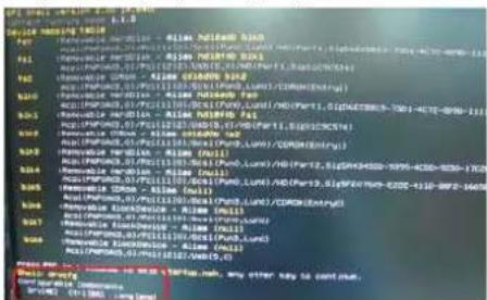
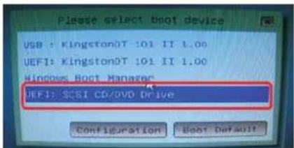
- Press to enter Boot Manual. Choose UEFI: Built-in EFI Shell.
- Key in drivcfg, for example you will see below:
Drv[4E] Ctrl[B5] Lang[eng]
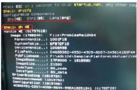
- Key in dh [Drv number], for example: key in dh 4E.
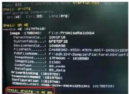
- And then key in drivcfg -s [Drv number] [Ctrl number] to enter Fiat Utility. For example: key in drivcfg -s 4E B5.
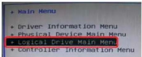
- Choose Logical Drive Main Menu to set up RAID Drive.
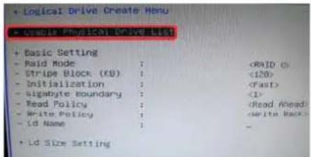
- Choose Logical Drive Create Menu to create a Raid Drive.

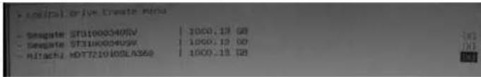
- Choose Usable Physical Drive List to select Raid HDD.
- Press Space on keyboard to toggle checkbox.
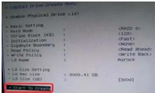
- Choose Ld Size setting, and key in the Raid size.
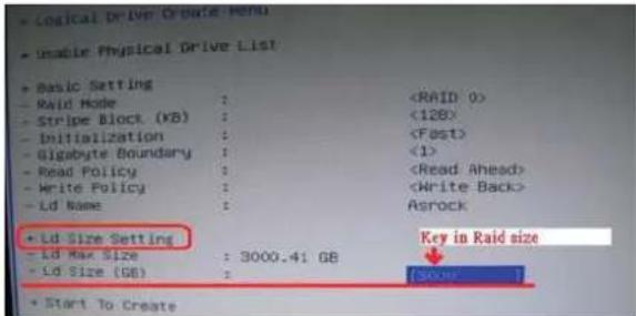
- After set up Raid size, please click Start to Create.
-
Press to exit Utility.
-
During reboot, please press to enter Boot Manual. Choose UEFI: SCSI CD/DVD Drive.
- This option only shows on Windows® 7 64-bit and Vista™ 64-bit OS.
English
- Follow Windows Installation Guide to install OS.
If you install Windows® 7 64-bit / Vista™ 64-bit in a large hard disk (ex. Disk volume > 2TB), it may take more time to boot into Windows® or install driver/ utilities. If you encounter this problem, you will need to following instructions to fix this problem.
Windows Vista™ 64-bit:
Microsoft does not provide hotfix for this problem. Below steps are Microsoft suggested solution:
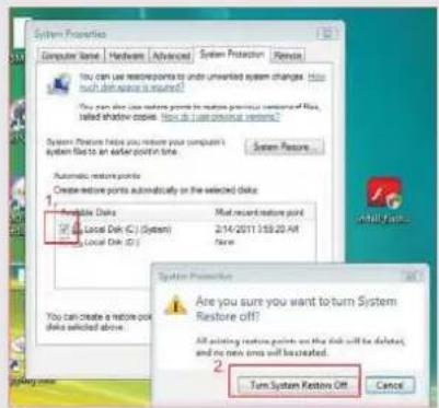
A. Disable System Restore.
a. Type "systempropertiesprotection" in the Start Menu. Then press
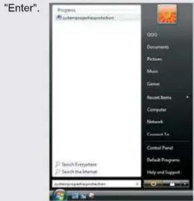
b. De-select Local Disks for System Restore. Then Click "Turn System Restore Off" to confirm. Then Press "OK".
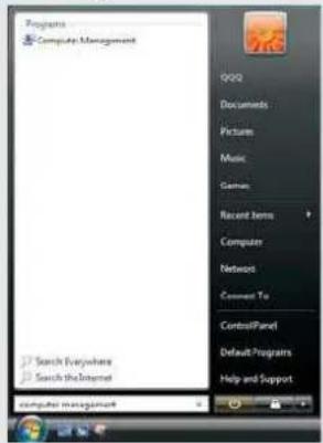
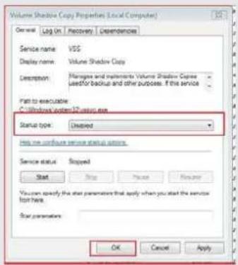
B. Disable "Volume Shadow Copy" service.
a. Type "computer management" in the Start Menu, then press "Enter".
b. Go to "Services and Applications>Services"; Then double click "Volume
Shadow Copy".
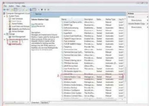
c. Set "Startup type" to "Disable" then Click "OK".
en ennnn
C. Reboot your system.
D. After reboot, please start to install motherboard drivers and utilities.
Windows 7 64-bit:
A. Please request the hotfi x KB2505454 thru this link: http://support.microsoft.com/kb/2505454/
B. After installing Windows® 7 64-bit, install the hotfi x kb2505454. (This may take long time; >30 mins.)
C. Reboot your system. (It may take about 5 mins to boot.)
D. The Windows® will install this hotfi x then reboot by itself.
E. Please start to install motherboard drivers and utilities.
- Finish.
usu