GDT635HSRSS - Washing machine GE - Free user manual and instructions
Find the device manual for free GDT635HSRSS GE in PDF.


| Product Type | Built-in Dishwasher |
| Brand | GE |
| Model | GDT635HSRSS |
| Minimum Height (with rollers) | 86.4 cm (34 in) |
| Minimum Height (without rollers) | 85.1 cm (33.5 in) |
| Width | 60.4 cm (23 7/8 in) |
| Depth (with door) | 62.6 cm (24 5/8 in) |
| Depth (without door) | 61.0 cm (24 in) for models with custom panel |
| Electrical Supply | 120 V AC, 60 Hz, 15 A or 20 A |
| Electrical Connection Type | Power cord or direct connection |
| Required Water Pressure | 138 to 862 kPa (20 to 120 psi) |
| Recommended Water Temperature | 49 °C (120 °F) |
| Recommended Detergent Type | Premium pre-measured tablets or packs |
| Rinse Agent | Required for optimal performance, refill every 1 to 3 months |
| Load Capacity | Standard (not specified, but removable upper rack) |
| Wash Cycles | Sensor, Tough, Cookware, Normal, Sani Rinse, etc. |
| Sanitization Feature | Yes, NSF/ANSI 184 certified |
| Settings Menu | Rinse level, sound, interior light, Sabbath mode, factory reset |
| Tub Material | Stainless steel (indicated by notch lines) |
| Noise | Adjustable: sound on/off |
| Weight (approx.) | Not provided, estimated ~45-55 kg |
| Error Code Display | 7-segment display or flashing LED indicators |
| Warranty | Not specified in the manual, refer to quick start guide |
Frequently Asked Questions - GDT635HSRSS GE
User questions about GDT635HSRSS GE
0 question about this device. Answer the ones you know or ask your own.
Ask a new question about this device
Download the instructions for your Washing machine in PDF format for free! Find your manual GDT635HSRSS - GE and take your electronic device back in hand. On this page are published all the documents necessary for the use of your device. GDT635HSRSS by GE.
USER MANUAL GDT635HSRSS GE
OWNER'S MANUAL MANUEL DE L'UTILISATEUR MANUAL DEL PROPIETARIO
TABLE OF CONTENTS/TABLE DES MATIÈRES/ÍNDICE
DISHWASHER MAINTENANCE .....3
DISHWASHER LOADING TIPS......4
DISHWASHER CARE....5
DISHWASHER SETTING MENU.....6
ERROR CODES......7
Error codes / blinking lights....7
INSTALLATION REQUIREMENTS...8
Tools and parts 8
Location requirements....10
Product and cabinet opening
dimensions:....11
Drain requirements ....12
Water supply requirements....12
Electrical requirements ......12
INSTALLATION INSTRUCTIONS...13
Prepare cabinet opening—
new utilities....13
Install optional moisture barrier -
recommended for wood countertops ...13
Electrical connection 14
Prepare dishwasher....15
Remove access panel and insulation....15
Disconnect and remove drip tray assembly....15
Connect water line to fill valve....16
Connect fill hose to fill valve....17
Drain hose connection....18
Power cord connection....18
Install door handle
(on some models)....20
Place dishwasher in cabinet....20
Custom panel installation
(custom panel models only)......21
Choose anchor attachment method...21
Final installation check....22
Secure dishwasher in cabinet
opening....23
Connect water line to house
shut-off valve 24
Connect drain hose 24
Complete installation....26
Check operation 27
Install access panels....27
If dishwasher does not operate .....28
ENTRETIEN DU LAVE-VAISSELLE....30
CONSEILS DE CHARGEMENT DU LAVE-VAISSELLE .... 31
ENTRETIEN DU LAVE-VAISSELLE....32
MENU DE RÉGLAGE DU LAVE-VAISSELLE : 33
Your safety and the safety of others are very important.
We have provided many important safety messages in this manual and on your appliance. Always read and obey all safety messages.

This is the safety alert symbol.
This symbol alerts you to potential hazards that can kill or hurt you and others.
All safety messages will follow the safety alert symbol and either the word "DANGER" or "WARNING."
These words mean:
DANGER
You can be killed or seriously injured if you don't immediately follow instructions.
WARNING
You can be killed or seriously injured if you don't follow instructions.
All safety messages will tell you what the potential hazard is, tell you how to reduce the chance of injury, and tell you what can happen if the instructions are not followed.
IMPORTANT SAFETY INSTRUCTIONS
WARNING: When using the dishwasher, follow basic precautions, including the following:
- Read all instructions before using the dishwasher.
■ Use the dishwasher only for its intended function.
■ Use only detergents or rinse agents recommended for use in a dishwasher, and keep them out of the reach of children.
■ When loading items to be washed: - Read all instructions before using the dishwasher.
- Use the dishwasher only for its intended function.
- Use only detergents or rinse agents recommended for use in a dishwasher, and keep them out of the reach of children.
- When loading items to be washed:
■ Do not tamper with controls.
■ Do not abuse, sit on, or stand on the door, lid, or dish racks of the dishwasher.
■ Do not use replacement parts that have not been recommended by the manufacturer (e.g. parts made at home using a 3D printer).
■ To reduce the risk of injury, do not allow children to play in or on the dishwasher.
■ Under certain conditions, hydrogen gas may be produced in a hot water system that has not been used for two weeks or more. HYDROGEN GAS IS EXPLOSIVE. If the hot water system has not been used for such a period, before using the dishwasher turn on all hot water faucets and let the water flow from each for several minutes. This will release any accumulated hydrogen gas. As the gas is flammable, do not smoke or use an open flame during this time.
■ Remove the door or lid to the washing compartment when removing an old dishwasher from service or discarding it.
SAVE THESE INSTRUCTIONS
GROUNDING INSTRUCTIONS
■ For a grounded, cord-connected dishwasher:
The dishwasher must be grounded. In the event of a malfunction or breakdown, grounding will reduce the risk of electric shock by providing a path of least resistance for electric current. The dishwasher is equipped with a cord having an equipment-grounding conductor and a grounding plug. The plug must be plugged into an appropriate outlet that is installed and grounded in accordance with all local codes and ordinances.
WARNING: Improper connection of the equipment-grounding conductor can result in a risk of electric shock.
Check with a qualified electrician or service representative if you are in doubt whether the dishwasher is properly grounded. Do not modify the plug provided with the dishwasher; if it will not fit the outlet, have a proper outlet installed by a qualified electrician.
■ For a permanently connected dishwasher:
The dishwasher must be connected to a grounded metal, permanent wiring system, or an equipment-grounding conductor must be run with the circuit conductors and connected to the equipment-grounding terminal or lead on the dishwasher.
SAVE THESE INSTRUCTIONS
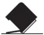
WARNING
Tip Over Hazard
Do not use dishwasher until completely installed.
Do not push down on open door.
Doing so can result in serious injury or cuts.
DISHWASHER MAINTENANCE
Detergents
High-quality premeasured tablets and packs are recommended for improved performance.
Quality tablets and packs have been proven better than powder, liquid, or gel detergents at reducing filming on dishes. Using tablets and packs over time will start to reduce or eliminate white film. They are suitable for all water hardness and soil levels. Also, by using a rinse aid, you can minimize repeat buildup of white film (not all packs and tablets contain rinse aid). Always place premeasured detergents in main compartment and close lid.
NOTE: Follow instructions on the package when using other dishwasher detergent types.
■Use automatic dishwasher detergent only. Add detergent just before starting a cycle.
■Fresh automatic dishwasher detergent results in better cleaning. Store tightly closed detergent container in a cool, dry place.
■Extremely hard water mineral deposits (15 grains per U.S. gallon or more) can cause damage to your dishwasher and make it difficult to achieve good results. A water softener is recommended to avoid damage and achieve good results.
■For more details about powders, liquids, and gels and hard water conditions consult the brand website.
Rinse aid
Using rinse aid will optimize your drying and wash performance. This dishwasher is specifically designed to be used with rinse aid for improved drying performance and controlling buildup of hard water deposits. Rinse aid needs to be added to the product every 1 to 3 months depending on usage.
Refer to the Quick Start Guide or brand website for information about filling the rinse aid dispenser.
Cycle Selection and Energy
Efficient dishwashers run longer to save water and energy, just as driving a car slower saves on gas. Typical cycle time is approximately 2 1/2 hours, but can take less or significantly more time depending on your selections and incoming water temperature and amount of food soils on the dishes. For optimum performance the dishwasher should be connected to a 120 F (49°C) hot water supply.
If you first press the Start button, the main sensor cycle with heated drying will be automatically selected. This cycle senses the soil amount, and toughness of soil, to adjust the cycle for improved cleaning.
Sanitize or Sani
Sanitizes dishes and glassware in accordance with NSF International NSF/ANSI Standard 184 for Residential Dishwashers. Certified residential dishwashers are not intended for licensed food establishments. Only sanitizing cycles have been designed to meet the requirements of the NSF/ANSI 184 performance standard for soil removal and for sanitization efficacy. There is no intention, either directly or indirectly, that all cycles on a NSF/ANSI 184 certified dishwasher meet the NSF/ANSI 184 performance standard for soil removal and for sanitization efficacy. The Sani Rinse indicator glows at the end of the cycle if the Sani Rinse option was successfully completed. If the indicator does not activate, it is probably due to the cycle being interrupted.
DISHWASHER LOADING TIPS
NOTE: Features are model specific. Your dishwasher may not have all features described.
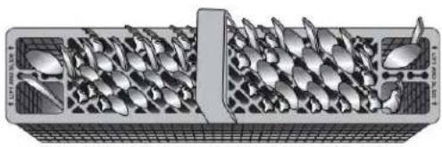
Silverware Baskets
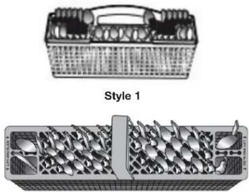
Style 2
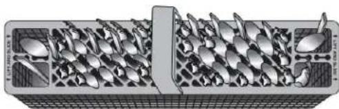
Use silverware basket lids to provide optimal spacing and best cleaning performance.
NOTE: If your silverware does not fit into the designated slots, open the lids (Style 1) or lift on the ends of the lids and pull to remove (Style 2). Mix silverware types to keep them separated. Load knives down, forks up, and alternate spoons for best cleaning results.
Removing Upper Racks
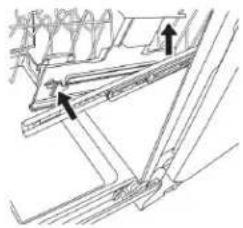
In order to make space for tall items, your upper racks are removable. The manner in which to remove will depend on whether the rack is mounted with Style 1 or Style 2. Remove dishes prior to removing any racks.
natural_image
Technical line drawing of a structural frame with two arrows indicating connection points (no text or symbols present)Style 1
To remove the rack, pull the rack forward about halfway out of the tub. On one side, press the tab on the track in and pull up the front end of the rack, out of the track. Then repeat this step on the other side to completely remove the front end of the rack. Then remove the rack by pulling the back end out using a forward and upward motion.
To replace the rack, Push back of rack into rail first and then push front down.
text_image
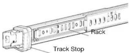
Track Stop RackStyle 2
To remove the rack, pull the rack out until it stops. On the left and right side of the rack, push the plastic track stops on the front of the rail sideways to open them. Pull out the rack.
To replace the rack, push the rack back onto the rails. Push the track stops closed.
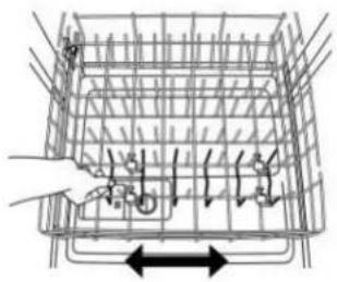
Sliding Bowl Tines
natural_image
Diagram of a container with internal structure and directional arrows indicating movement (no text or symbols)The sliding bowl tines allow you to easily load bowls of multiple sizes. Grab the moveable tine row in the lower rack and slide into the desired position.
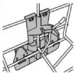
Fold Down Tines
natural_image
Technical line drawing of a mechanical assembly or bracket (no text or symbols)Fold down tines allow you to optimize the spacing in the rack. Fold down tines might be in the lower rack, the second level rack and/or third level rack depending on your model. To fold or unfold the tine, hold the tine nearest the clip at the end of the tine row and gently push it past the stop on the clip and in the direction you want to fold it.
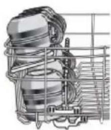
Stemware Holder
Use the stemware holders to support wine glasses and other stemware. Push them up to rotate them out of the way when not needed.

text_image
Stemware HolderCup Shelf
natural_image
Technical line drawing of a mechanical assembly with gears and housing (no text or symbols)Use the cup shelf to hold additional cups or small items. Push up to fold out of the way when not needed.
DISHWASHER CARE
Interior Cleaning
Many detergents may leave white spots or a white residue on dishware and on the interior of the dishwasher. Over time this residue can become unsightly and could affect dishwasher performance. Use of a dishwasher cleaning product such as affresh® Dishwasher Cleaner can help to remove the residue. Monthly use of affresh® Dishwasher Cleaner is recommended to help maintain the dishwasher. Follow package directions.
NOTE: We recommend the use of high-quality, premeasured detergent tablets or packs and the use of rinse aid for dishwasher cleaning and daily care.
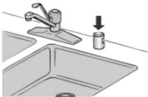
Countertop Air Gap
If you have a drain air gap, check and clean it if the dishwasher isn't draining well.
natural_image
Illustration of a kitchen sink with a faucet and a bucket being inserted (no text or symbols)Extended Time Without Use
To Reduce Risk of Property Damage During Vacation or Extended Time Without Use
■When you will not be using the dishwasher during the summer months, turn off the water and power supply to the dishwasher.
■ Make sure the water supply lines are protected against freezing conditions. Ice formations in the supply lines can increase water pressure and cause damage to your dishwasher or home.
■Damage from freezing is not covered by the warranty.
■When storing your dishwasher in the winter, avoid water damage by having your dishwasher winterized by authorized service personnel.
Exterior Cleaning
Clean the exterior of dishwasher with a soft, damp cloth and mild detergent. Avoid using abrasive cleaning products on the exterior of the dishwasher. Abrasive cleaning products can damage the finish.
Troubleshooting
The brand website listed on the Quick Start Guide has detailed information to troubleshoot most problems customers encounter. This information may save you the cost of a service call.
Foreign Object Cup
If the Foreign Object Cup is full the Quick Start Guide or the brand website listed on the Quick Start Guide has detailed information about how to empty it.
DISHWASHER SETTING MENU:
Follow the below instructions to enter into the menu to change your current settings.
| Menu | Display Text(if display is present) | LED Pattern (no display) | What this setting does | Default Setting | ||
| PROWASH OR SENSOR | TOUGH OR COOKWARE | NORMAL | ||||
| Rinse Aid Level A | X Adjust amount of rinse aid dispensed | |||||
| Rinse Aid Level sub-menu | A 0 X X | X 0 mL - rinse aid off | ||||
| A 1 X 1 mL X | ||||||
| A 2 X 2 mL | ||||||
| A 3 X X | 3 mL | |||||
| A 4 X 4 mL | ||||||
| A 5 X | X 5 mL | |||||
| A 6 X | X 6 mL | |||||
| Sound Level S X | X Turn sound On and Off | |||||
| Sound Level sub-menu | S 1 X Sound On | X | ||||
| S 0 X Sound Off | ||||||
| Light in Tub | L | X | Turn the inner light on and off (if present) | |||
| Lights in Tub sub-menu | L 1 | X | Light in Tub ON when door is opened | X | ||
| L 0 | X Light in Tub OFF when door is opened | |||||
| Kosher Consumer Friendly mode | E | X | X | Turn Kosher Consumer Friendly mode On and Off | ||
| E 1 X | Turn mode | ON | ||||
| E 0 X Turn mode OFF | X | |||||
| Factory Reset | r | X | X | X | Factory Reset | |
- Press and hold the "Hi Temp" button for 5 seconds until "Hi Temp" and "Dry" lights turn on.
- Press the "Start/Resume" button within 2 seconds. If you do not press Start within 2 seconds, then the display will turn off and you will need to start over and go back to step 1.
a. For Models with a Display, an "A" will show in the display to indicate Rinse Aid Level.
b. For Non-display models, "Tough or Cookware" light will turn on to indicate Rinse Aid Level.
- To go to a feature other than Rinse Aid Level, press the "Cycle" button or "Normal" button (depending on model) to move to the feature you would like to change (Sound Level, Light in Tub, Kosher Friendly, Factory Reset, Rinse Aid Level). See the table for what is shown on the display to indicate these features.
- Press the "Start/Resume" button to select the feature and enter the sub-menu. The display will change to show the current setting of the feature. (For example, if you selected Sound Level and you haven't changed it before, then S1 will show for display models and sensor will light for non-display models.)
- Press "Cycle" button or "Normal" button (depending on model) to change the value of the feature setting. (For example, if you want to turn the sound off, then press the "Cycle" or "Normal" button and S0 shows on display models or "pots and pans" lights for non-display models.)
- Press the "Start/Resume" button to confirm the new selection. The feature setting will not be changed until the "Start/Resume" button is pressed.
The dishwasher will return to the Off state when the Start button is pressed.
To exit the customer settings menu at any time, press the "Cancel" button, or wait 30 seconds without pressing any buttons.
NOTE: To see the current setting of a feature, follow steps 1-4. When the "Start/Resume" button is pressed in step 4, the dishwasher will show the current setting. Press the "Cancel" button to exit without making any changes.
NOTE: If you enter into a Feature Setting Page and need to go back to the Main Menu Press "Cancel" and proceed to step 1.
NOTE: To exit "Kosher Consumer Friendly Mode" at any time, press the "Cancel" button or you can wait 72 hours.
Kosher Consumer Friendly Mode: When turned on, will disable all of the buttons on the dishwasher except for the cancel key, and disable the light inside the tub (if equipped) for a time period of 75 hours. If this mode is turned on during a cycle, then the status lights at the end of cycle will not turn off when the door is opened and then re-closed. To exit this mode, press the “Cancel” button, or wait 75 hours.
ERROR CODES
ERROR CODES / BLINKING LIGHTS
| Issue | Code Shown(7 Seg Display)(if present) | Code Shown on Front Panel LED *(# blinks, Pause, #blinks) | What will happen? What to do? | |
| Dishwasher fails to operate fill valve correctly | F1E1 | 1 Pause 1 Pause - pause, repeat | Drain sequence will begin, machine operation will be prevented | Turn off water to unit (if possible).Turn off power to unit. If the water cannot be turned off, DO NOT turn off power and keep door closed. Press Cancel key one time to silence alarm tone. Call service. |
| Motor controller failure | F1E2 | 1 Pause 2 Pause, repeat | Cycle ends Call service | |
| No water present at dishwasher | H2O | 8 Pause 1 Pause - pause, repeat | Cycle is paused | Ensure fill hose is connected to product. Ensure water supply is turned ON. Press Start to resume cycle. If alarm still present, call service. |
| Wash motor failure F7E2 | 7 Pause 2 Pause, repeat | Cycle ends Call service | ||
| Dishwasher overfills | F8E4 | 8 Pause 4 Pause - pause, repeat | Drain sequence will begin, machine operation will be prevented | Turn off water to unit (if possible).Turn off power to unit. If the water cannot be turned off, DO NOT turn off power and keep door closed. Press Cancel key one time to silence alarm tone. Call service. |
| Fill valve stuck on F8E5 | 8 Pause 5 Pause - pause, repeat | Drain sequence will begin, machine operation will be prevented | Turn off water to unit (if possible).Turn off power to unit. If the water cannot be turned off, DO NOT turn off power and keep door closed. Press Cancel key one time to silence alarm tone. Call service. | |
| Dishwasher will not drain | F9E1 | 9 Pause 1 Pause - pause, repeat | Cycle ends | If drain hose is connected to a garbage disposal, confirm that drain hose is not clogged and disposal plug has been knocked out. If unit still will not drain, call service. |
| Water present under dishwasher | FAE5 | 10 Pause 5 Pause - pause, repeat | Cycle ends Call service. | |
| User interface service communication fault | F6E1 | 6 Pause 1 Pause - pause, repeat | Product will not able to start or resume cycles | Call service. |
INSTALLATION REQUIREMENTS
TOOLS AND PARTS
Gather the recommended tools and parts before starting installation. Read and follow the instructions provided with the tools listed here.
All Installations
Tools Needed:

natural_image
Two line drawings of pliers, no text or symbols present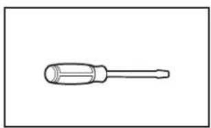
natural_image
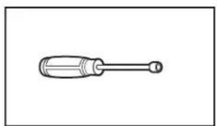
Line drawing of a screwdriver with a cylindrical head and threaded shaft (no text or symbols)Pliers Flat-blade screwdriver
natural_image
Simple line drawing of a screwdriver (no text or symbols)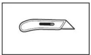
natural_image
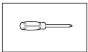
Simple line drawing of a flat tool with a handle and central slot (no text or symbols)Phillips screwdriver Utility knife
natural_image
Simple line drawing of a screwdriver with a cylindrical head and shaft (no text or symbols)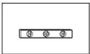
natural_image
Simple diagram with three circular symbols inside a rectangular box (no text or labels)5/16" (7.9 mm) and 1/4" (6.4 mm) nut drivers or hex sockets
natural_image
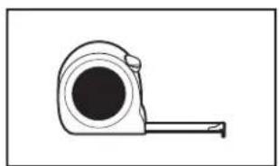
Simple line drawing of a tape measure (no text or symbols)Small level
natural_image
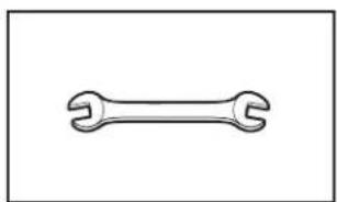
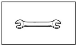
Simple line drawing of a double-ended wrench (no text or symbols)Measuring tape or ruler 5/8" (15.9 mm) open-end wrench
natural_image
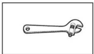
Line drawing of an adjustable wrench (no text or symbols)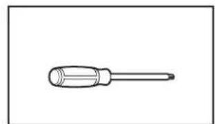
natural_image
Simple line drawing of a screwdriver (no text or symbols)10" adjustable wrench that opens to 1^1/8 " (29 mm)
Torx ^† T20 and, if installing custom front panels, Torx T15 screwdrivers
Other Useful Items You May Need:
natural_image
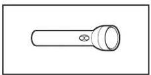
Simple line drawing of a flashlight with a bulb and handle (no text or symbols)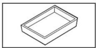
natural_image
Simple line drawing of a rectangular tray or container (no text or symbols)Flashlight Shallow pan
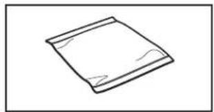
natural_image
Simple line drawing of a folded paper or plastic sheet (no text or symbols)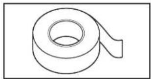
natural_image
Simple line drawing of a rolled-up tape or tape (no text or symbols)Bath towel Masking, or duct tape
Parts Supplied:
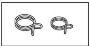
natural_image
Two identical rope knot diagrams shown side by side (no text or symbols)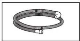
natural_image
Coiled cable or hose component with two connectors (no text or symbols visible)Drain hose clamps (2)
(1 large/red and 1 small/silver)
natural_image
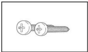
Illustration of a screw with two circular fasteners (no text or symbols)Drain hose
natural_image
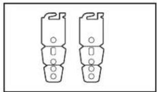
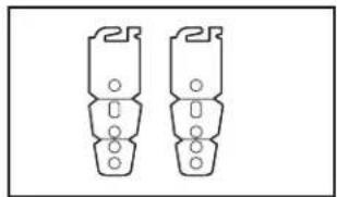
Two identical mechanical component diagrams with mounting holes, no text or symbols present8 x 1/2" (12.7 mm) Phillips-head screws (2)
Undercounter mounting brackets (2)
Make sure all parts are included in the literature package.
natural_image
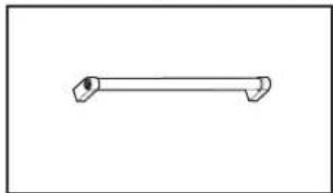
Simple line drawing of a horizontal pipe or lever (no text or symbols)Door handle (on some models)
†TORX, T15, and T20 are trademarks of Acument Intellectual Properties, LLC.
Other Parts Needed (not provided):
natural_image
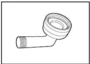
Line drawing of a pipe fitting with a flanged end (no text or symbols)3/8" (9.5 mm) Compression x 3/4" (19 mm) Hose Fitting with rubber seal and 90° elbow (required to properly connect household water line to the dishwasher.)
Part no: W10685193

natural_image
Technical line drawing of a mechanical component with threaded ends and a central circular feature (no text or symbols)Household Wiring (Metallic) Strain Relief to fit 7/8" (22 mm) hole (required to properly secure household wiring to the dishwasher terminal box.)
Part no: 4396672
NOTE: Use only UL Listed/CSA Approved parts.
Optional Accessory Parts Available:
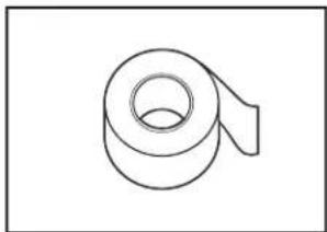
natural_image
Simple line drawing of a rolled-up adhesive tape (no text or symbols)Moisture Barrier Tape
NOTE: Moisture barrier tape is an optional, added level of protection if installing a dishwasher under a wooden countertop. Recommended but not required for wooden countertop.
Part no: 4396277
natural_image
Simple geometric diagram with two concentric squares (no text or symbols)Side Panel Kit
For enclosing the side of the dishwasher when installing it at the end of your cabinetry (Whirlpool part number varies with color).
Call us at our toll-free number or visit the brand website listed in the Quick Start Guide for accessory and part information.
First-Time Installations
Check local codes. Check existing electrical supply. See the "Electrical Requirements" section. It is recommended that electrical connections be made by a licensed electrical installer.
Additional Tools Needed:
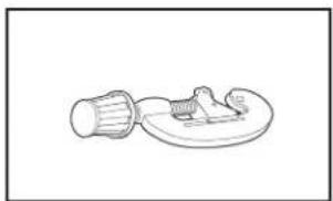
natural_image
Simple line drawing of a mechanical component with a cylindrical shaft and flanged base (no text or symbols)
natural_image
Line drawing of a pair of pliers (no text or symbols)Small tubing cutter Wire stripper
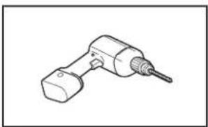
natural_image
Line drawing of a handheld electric drill bit (no text or symbols)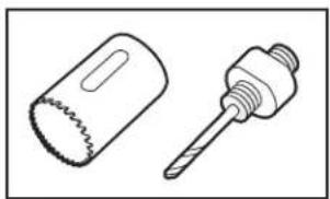
natural_image
Technical line drawing of two mechanical components: a saw blade and a threaded screw (no text or symbols)Cordless drill 1/2" (12.7 mm), 3/4" (19 mm), and 1½" (38 mm) hole saw bits
Additional Parts Needed (not provided):

natural_image
Line drawing of a coiled hose and a separate connector (no text or symbols)Copper Tubing (3/8" O.D. suggested) or Flexible Braided Water Supply Line Kit. Kit includes braided hose and 3/8" compression x 3/4" hose fitting.
Part no: W10278635RP
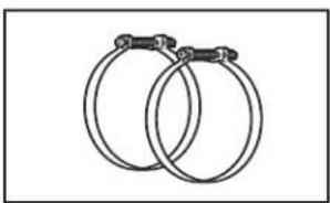
natural_image
Two interlocked rings with metal clips (no text or symbols)Screw-Type Clamps 1 ^1/2 " - 2" (38 mm - 50 mm) (3 maximum)
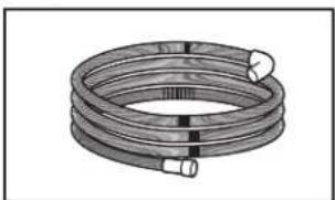
natural_image
Coiled industrial hose with flanged ends and connectors (no text or symbols visible)Optional-Longer Drain Hose (Maximum length 12 ft (3.7 m)
NOTE: Must meet AHAM/ IAPMO test standards, fit 1" (25 mm) drain connection, and be resistant to heat and detergent.
Part no: W11381654
NOTE: If using a flexible braided hose, replace inlet hose after 5 years to reduce the risk of hose failure. Record hose installation or replacement dates on the hose for future reference.
NOTE: Be sure to purchase only Whirlpool factory-certified parts and accessories for your appliance. Your installation may require additional parts. To order, refer to the contact information referenced in your Quick Start Guide.
For Direct Wire For Power Cord
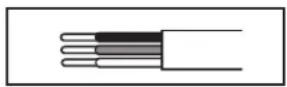
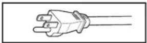
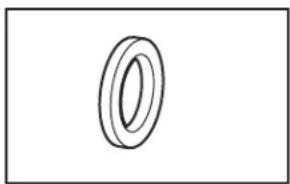
natural_image
Simple line drawing of a ring shape with no text or symbols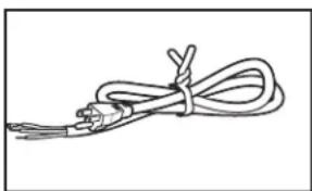
natural_image
Simple line drawing of a coiled cable or wire with connectors (no text or symbols)Cabinet Grommet
For 1^1/2 " (38 mm) hole in cabinet.
NOTE: Required for metal cabinets
Power Cord Kit
Kit typically includes
power cord, metallic strain relief, grommet.
(Whirlpool Part Number
Cord Kit - Straight - W11365011
Cord Kit - Right Angle - W11365014)
Call us at our toll-free number or visit the brand website listed in the Quick Start Guide for accessory and part information.
NOTE: Be sure to purchase only Whirlpool factory-certified parts and accessories for your appliance. Your installation may require additional parts. To order, refer to the contact information referenced in your Quick Start Guide.
LOCATION REQUIREMENTS
Dishwasher must be fully enclosed (top, sides, back, and floor) upon installation. A side panel kit is available from your dealer for installing your dishwasher at the end of your cabinetry.
An optional moisture barrier accessory is also available for installing underneath a wooden countertop.
Check location where dishwasher will be installed. The location must provide:
■Convenient access for loading and unloading dishes. Corner locations require a 2" (5.1 cm) minimum clearance between the side of the dishwasher door and the wall or cabinet.
■Easy access to water, electricity, and drain:
■Grounded electrical supply is required.
■This dishwasher has a water heating feature and also requires a connection to a hot water supply line.
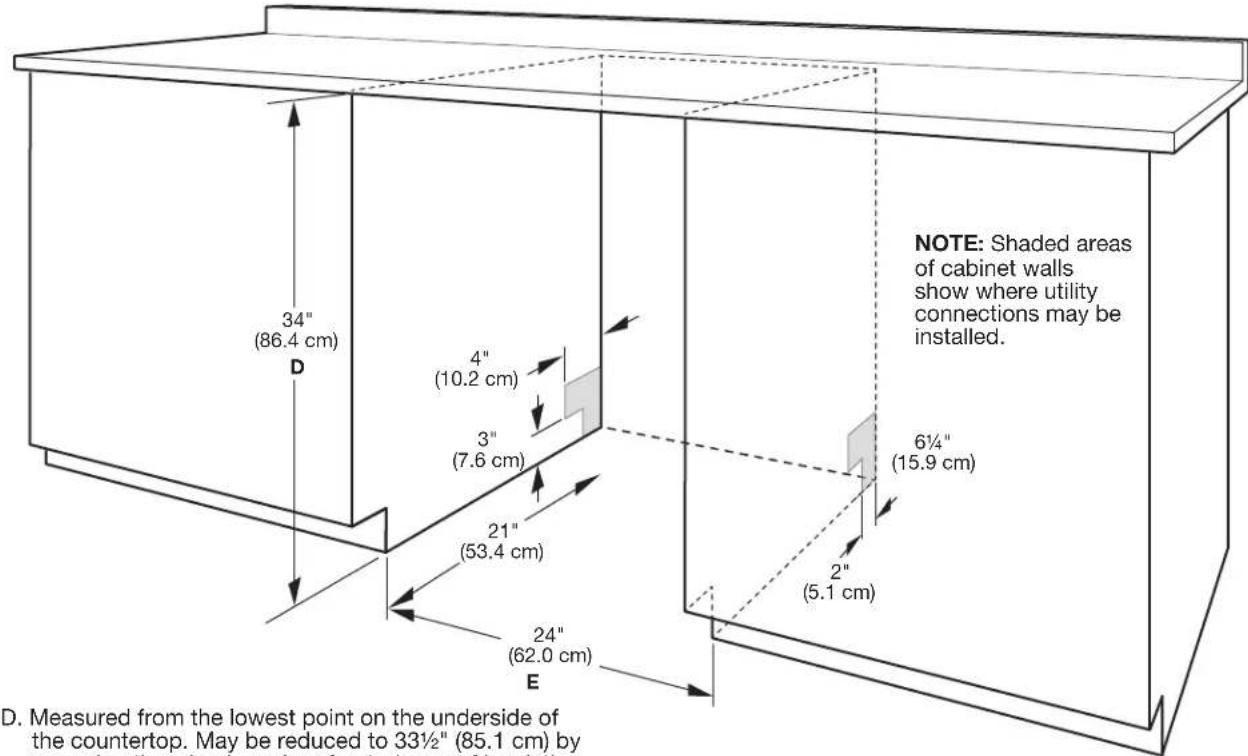
■Make sure pipes, wires and drain hose are within the shaded area shown in the "Product and Cabinet Opening Dimensions" section.
■ Do not run drain lines, water lines, or electrical wiring where they can interfere with or contact dishwasher motor or legs.
■Shelter dishwasher and water lines leading to dishwasher against freezing. Damage from freezing is not covered by the warranty.
NOTE: If dishwasher will be left unused for a period of time or in a location where it may be subject to freezing, have it winterized by authorized service personnel.
If installed in new construction, flush the water supply line of debris before connecting it to the fill valve. If it is not flushed, debris from the water supply could plug the fill valve screen.
■A square opening for proper operation and appearance.
■The cabinet front to be perpendicular to floor.
■Level floor.
Helpful Tip: If floor at front of opening is not level with floor at rear of opening, shims may be used to level dishwasher.
NOTE: To avoid shifting during dishwasher operation, shims must be securely attached to the floor.
■The location where the dishwasher will be installed must provide clearance between motor and flooring. Motor should not touch the floor.
■Do not install dishwasher over carpeted flooring.
PRODUCT AND CABINET OPENING DIMENSIONS:
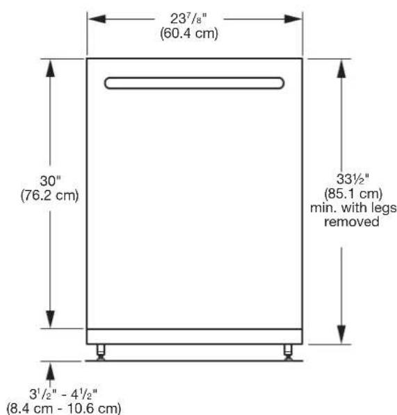
text_image
23½" (60.4 cm) 30" (76.2 cm) 33½" (85.1 cm) min. with legs removed 3½" - 4½" (8.4 cm - 10.6 cm)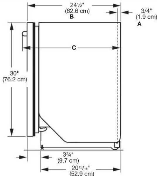
text_image
24½" (62.6 cm) B 3/4" (1.9 cm) A C 30" (76.2 cm) 3¾" (9.7 cm) 20¹³/¹⁸" (52.9 cm)A. Insulation may be compressed (not used on all models).
B. For panel-ready models, dishwasher depth is 24" (61.0 cm), not including the 3/4" (1.9 cm) custom door panel.
C. Door handles may protrude forward of the face of the dishwasher, varies by model.
Check that all surfaces have no protrusions that would prohibit dishwasher installation.
text_image
NOTE: Shaded areas of cabinet walls show where utility connections may be installed. 34" (86.4 cm) D 4" (10.2 cm) 3" (7.6 cm) 21" (53.4 cm) 24" (62.0 cm) E 6½" (15.9 cm) 2" (5.1 cm) D. Measured from the lowest point on the underside of the countertop. May be reduced to 33½" (85.1 cm) byD. Measured from the lowest point on the underside of the countertop. May be reduced to 33½" (85.1 cm) by removing the wheels and perforated area of insulation (blanket) on dishwasher.
E. Minimum, measured from narrowest point of opening.
DRAIN REQUIREMENTS
■ A new drain hose is supplied with your dishwasher. If drain hose is not long enough, use a new drain hose with a maximum length of 12 ft (3.7 m) that meets all current AHAM/ IAPMO test standards, is resistant to heat and detergent, and ts the 1" (2.5 cm) drain connector of the dishwasher.
NOTE: Do not connect multiple drain hoses together.
■ Make sure to connect drain hose to waste tee or disposer inlet above drain trap in house plumbing and 20" (50.8 cm) minimum above the oor. It is recommended that the drain hose either be looped up and securely fastened to the underside of the counter or be connected to an air gap.
■ Make sure to use an air gap if the drain hose is connected to house plumbing lower than 20" (50.8 cm) above sub nor or nor.
Use of air gap
Air gap
- If required, the air gap should be installed in accordance with the air gap installation instructions. When you are connecting the air gap, a rubber hose (not provided) will be needed to connect to the waste tee or disposer inlet. - Use 1/2" (1.3 cm) minimum I.D. drain line ttings.
WATER SUPPLY REQUIREMENTS
■ This dishwasher has a water heating feature and also requires a connection to a hot water supply line.
■ A hot water line with 20 psi to 120 psi (138 kPa to 862 kPa) water pressure can be verified by a licensed plumber.
■ 120°F (49°C) water at dishwasher.
ELECTRICAL REQUIREMENTS
Be sure that the electrical connection and wire size are adequate and in conformance with the National Electrical Code, ANSI/NFPA 70 - latest edition, and all local codes and ordinances.
A copy of the above code standards can be obtained from:
National Fire Protection Association
1 Batterymarch Park Quincy, MA 02169-7471
You Must Have:
■ 120 V, 60 Hz, AC only, 15 A or 20 A, fused electrical supply
■ Copper wire only
■ A maximum of 2-eld wiring supply conductors (12 AWG largest size) plus 1 grounding conductor are permitted in the terminal box.
We Recommend:
■ A time-delay fuse or circuit breaker.
Circuit Requirements:
■ The dishwasher may be installed on the same circuit as a garbage disposal providing that the branch circuit cannot exceed rated circuit load and must comply with all governing codes and regulations such as but not limited to National Electrical Code, ANSI/NFPA 70 - latest edition.
■ No electrical connections other than the dishwasher power and ground connections can be made inside of the dishwasher terminal box.
If connecting dishwasher with a power supply cord:
■ Use UL Listed power cord kit marked for use with dishwasher.
- Plug into a grounded 3 prong outlet. Outlet must meet all local codes and ordinances.
connecting dishwasher with direct wiring:
■ Use exible, armored, or nonmetallic sheathed copper wire with grounding wire that meets the wiring requirements for your home and local codes and ordinances.
■ Use a UL Listed/CSA Approved metallic strain relief.
INSTALLATION INSTRUCTIONS
WARNING

Electrical Shock Hazard
Disconnect electrical power at the fuse box or circuit breaker box before installing dishwasher.
Failure to do so can result in death or electrical shock.
STEP 1:
Video of installation steps can be found online at whirlpool.com in the "Service & Support" section "How To's & FAQ.
2. Disconnect power
Disconnect electrical power at the fuse box or circuit breaker box before installing dishwasher.
3. Shut off water supply
Shut off the water supply to the dishwasher.
PREPARE CABINET OPENING—NEW UTILITIES
- Drill hole locations—new construction

text_image
Optional location 1½" (3.8 cm) Preferred location 1½" (1.27 cm)The power-supply receptacle for the appliance shall be installed in a cabinet or on a wall adjacent to the undercounter space in which the appliance is to be installed.
NOTE: Refer to the "Product and Cabinet Opening Dimensions" section for the correct hole placement and dimensions of the shaded area.
Drill a 1½" (3.8 cm) drain hose hole in the side or rear of cabinet, depending on location of drain hose routing and drain hose connection location.
Drill a 1/2" (1.27 cm) water supply hose hole in the side or rear of cabinet, depending on location of water supply routing and connection location
Drill a 1½" (3.8 cm) electrical conduit hole in the right-hand side or rear of cabinet.
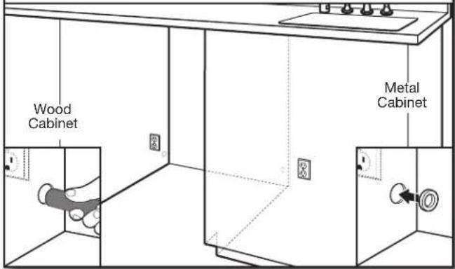
- Sand holes smooth
text_image
Wood Cabinet Metal CabinetWood cabinet: Sand the hole until smooth.
Metal cabinet: Cover edges of hole with grommet included with power cord kit.
Helpful Tip: Wiring the dishwasher will be easier if you route the cable into the cabinet opening from the right-hand side.
INSTALL OPTIONAL MOISTURE BARRIER - RECOMMENDED FOR WOOD COUNTERTOPS
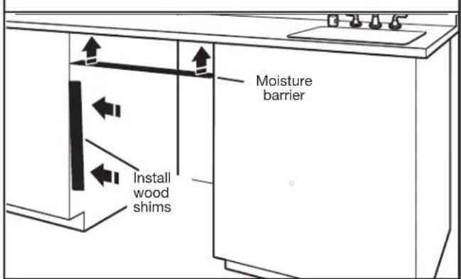
Moisture barrier/wood shims
text_image
Moisture barrier Install wood shimsMake sure the area under the cabinet is clean and dry for installation of the moisture barrier. Remove the backing of the moisture barrier, and apply to underside of the countertop along the front edge of the counter.
NOTE: The use of this moisture barrier is recommended but not required.
NOTE: Install wood shims if side anchoring and the gap between the sides of the cabinet and sides of the dishwasher are greater than 1/2" (1.27 cm) on each side or are greater than the length of the side anchor screws.
- Built-up floors – add shims as needed
text_image
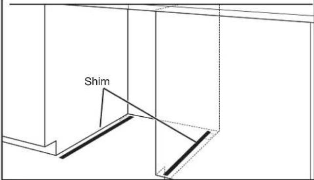
ShimNote: The wood runners that come with the shipping base work well for shims.
Built-up floors: If the kitchen floor is higher than the cabinet opening's floor - for example, the kitchen floor tile does not extend into the cabinet opening - add shims, as needed, in the area shown to bring cabinet floor up to same level as the kitchen floor.
NOTE: Shims must be securely attached to floor to avoid movement when the dishwasher is in use.
- If installing into a 33 ^1/2 " (85.1 cm) opening

natural_image
Simple line drawing of a rectangular box with a flat top and vertical side (no text or symbols)Cut insulation blanket along perforation for cabinet opening height of 33½" (85.1 cm). For other cabinet opening heights, do not cut the insulation blanket.
ELECTRICAL CONNECTION
- For Direct Wire, begin with Step 7
-
For Power Cord, wait until Step 18
-
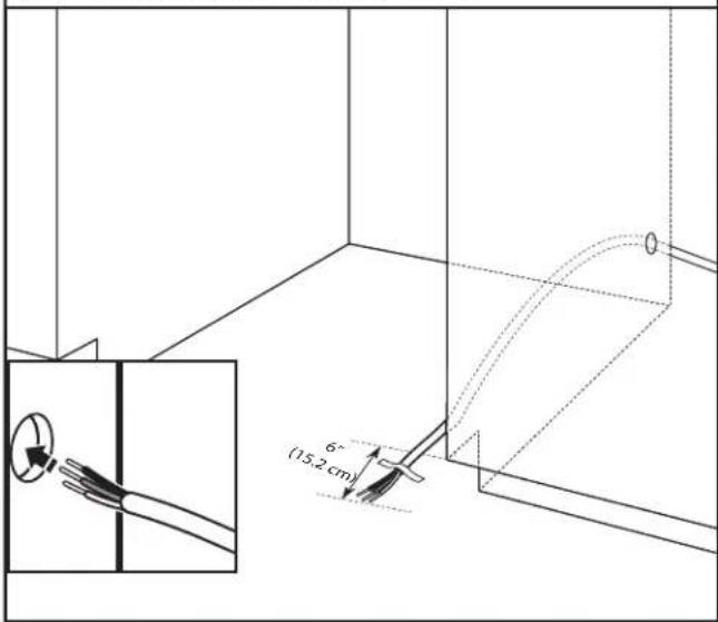
Direct wire - route cable
text_image
6" (15.2 cm)If installing with direct wire, route the cable as shown. Do not connect the wire to the product at this time. This connection will be made later, after the unit is installed into the cabinet opening. Route cable from power supply through cabinet hole. (Cable must extend to the right front side of cabinet opening.) Tape cable to the floor in area shown. This will prohibit cable from moving when dishwasher is moved into cabinet opening.
PREPARE DISHWASHER
WARNING
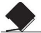
Tip Over Hazard
Do not use dishwasher until completely installed.
Do not push down on open door.
Doing so can result in serious injury or cuts.
WARNING
Excessive Weight Hazard
Use two or more people to move and install dishwasher.
Failure to do so can result in back or other injury.
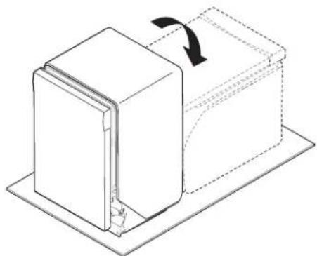
8. Put the dishwasher on its back
natural_image
Diagram of a mechanical assembly with a rectangular block and a curved component, showing motion direction (no text or symbols)Helpful Tip: Remove all internal shipping material, drain hose, installation kit, and handle (if included,) before laying on it's back, and not to remove film on the door at this time.
Place cardboard under dishwasher until installed
in cabinet opening to avoid damaging floor covering.
Using two or more people, grasp sides of dishwasher door frame, and place the dishwasher on its back.
Do not use the door panel as a worktable without first covering it with a towel to avoid scratching the door panel.
REMOVE ACCESS PANEL AND INSULATION
- Remove access panels
natural_image
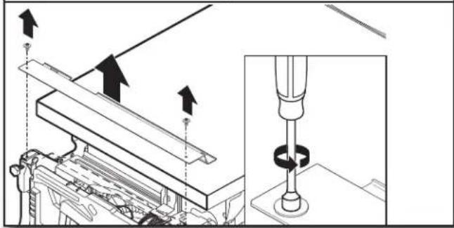
Technical diagram showing mechanical assembly with arrows indicating direction and a magnified inset of a drill bit (no text or symbols present)Using a 5/16" (7.9 mm) nut driver, remove the two screws attaching access panels to dishwasher. Once the screws are removed push the access panel toward the top of the project to unhook it and then remove it.
DISCONNECT AND REMOVE DRIP TRAY ASSEMBLY
10a. Remove drip tray assembly
text_image
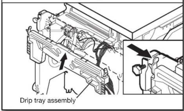
Drip tray assemblyTo remove the drip tray assembly, press the snap at each side of the plastic tray in toward the center of the product and pull toward yourself. Take caution not to pull too far or too hard as the float switch wire is still connected at this time.
10b. Remove float switch wire

natural_image
Technical line drawing of a mechanical component with internal parts and directional arrows (no text or symbols)To remove the float switch wire, gently push the connector latch tab (1) and then pull the connector (2) out of the housing. The float itself should not be removed from the tray.
NOTE: Not to install drip tray until instructed.
- Measure cabinet opening
natural_image
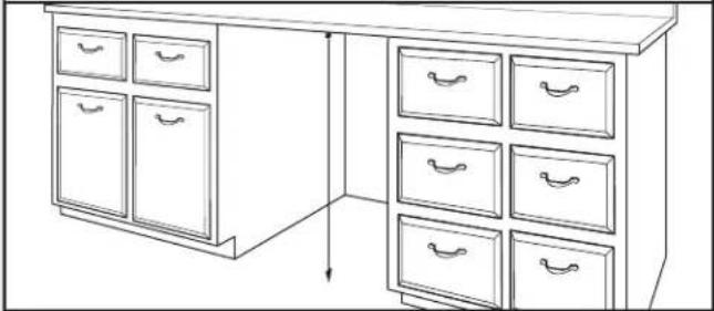
Line drawing of a cabinet with multiple drawers and drawers arranged in a row (no text or symbols)Measure the height of cabinet opening from the underside of the countertop to the floor where the dishwasher will be installed. Be sure to measure the lowest point on the underside of the countertop and the highest point on the floor.
Leveling leg adjustment
natural_image
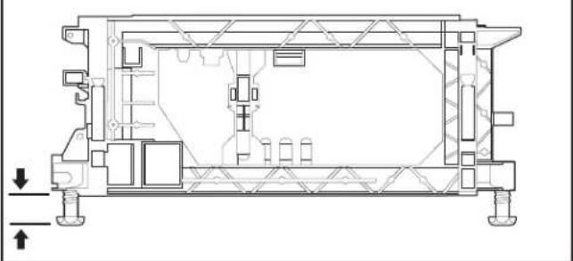
Technical cross-section diagram of a mechanical assembly (no text or labels visible)Use wrench to initially loosen leveling legs if needed.
Adjust all four leveling legs to the same height by rotating each foot clockwise or counterclockwise as needed.
The unit comes with the legs set for a 33½" (85.1 cm) height installation. If your opening height is 34½" (87.6 cm), you would therefore need to lower all four legs by 1" (2.54 cm).
NOTE: Adjust rear leg height first before moving unit into the cut out.
Legs can be removed if necessary for tight installations.
CONNECT WATER LINE TO FILL VALVE
- For Copper line, begin with Step 12
- For Flexible line, begin with Step 14
- Copper Water Line
natural_image
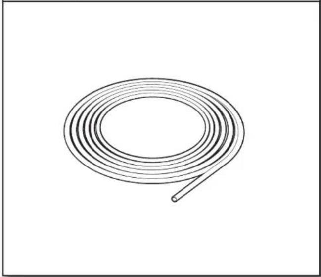
Simple line drawing of a coiled wire or tube, no text or symbols presentIf using copper tubing, measure overall length of copper tubing required to reach the water supply, cut to length, and attach with compression fittings.
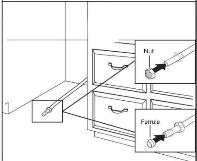
13. Slide nut and ferrule onto tubing (copper tubing only)
text_image
Nut FerruleCopper tubing only: Put the tubing into the 90° elbow fitting as far as it will go. (The copper tubing bends and kinks easily.) Push the nut and ferrule forward and tighten it, so that it sits right up against elbow threads.
NOTE: To avoid vibration during operation, route the water supply line so that it does not touch the dishwasher base, frame, or motor. If using copper tubing, skip step 14 and go to 15.
14. Flexible line
natural_image
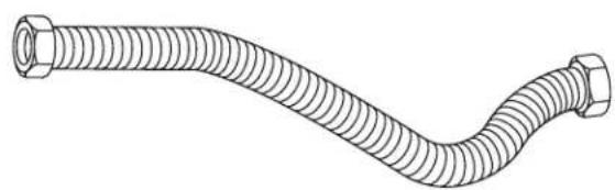
Line drawing of a flexible hose with threaded ends and two hexagonal connectors (no text or symbols)Flexible braided line: Confirm the flexible braided line is long enough.
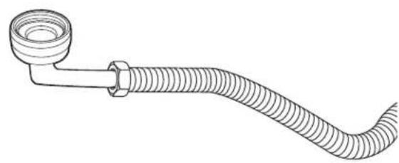
Get 3/8" compression x 3/4" hose fitting with 90° elbow. Connect the 3/8" compression fitting of the 90° elbow fitting to the water supply line. Attach such that the 3/4" connection is facing upward as shown above.
15. Add 90° elbow fitting to the water supply line
natural_image
Line drawing of a coiled hose with a flanged end (no text or symbols)CONNECT FILL HOSE TO FILL VALVE
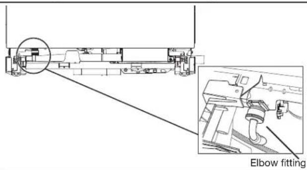
16. Tighten 90° elbow fitting to valve
text_image
Elbow fittingBe sure rubber washer is properly seated in fitting. Slide the 3/4" (19 mm) fitting of the 90° elbow up to the valve and hand tighten it to avoid cross-threading. Hand tighten until the coupling is tight.
Using pliers, check the tightness of the coupling. An additional 1/4 to 1/2 turn may be required to seal the rubber gasket. Route fill hose out the rear left side of unit.
NOTES:
■Do not use tape with compression fittings.
■Do not over-tighten. Damage to the coupling can result.
■ Route water supply line out rear of unit before setting unit up.
DRAIN HOSE CONNECTION
- Connect drain hose
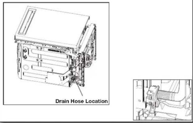
text_image
Drain Hose Location- Remove terminal box
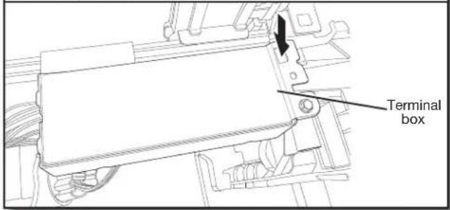
text_image
Terminal boxTo remove the terminal box, depress the plastic latch, slide the box toward the left of the unit along the metal tube and rotate the left side of the box forward. Make sure that the product wiring will still be attached within the terminal box.
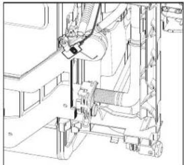
natural_image
Technical line drawing of a mechanical assembly with no visible text or symbolsPut provided silver clamp over elbow end of drain hose. Then push the hose onto the drain port with the hose facing underneath the dishwasher. Using pliers squeeze, open the drain hose clamp and slide it over the elbow to ensure those hose is attached in place. Route the hose out of the back of the product. NOTE:
■If the hose is installed with the rubber elbow facing out, the drain hose may become kinked causing slow or incomplete draining in tight cabinet installations.
■There may be a plastic plug in the drain port for shipping purposes where you will connect the drain hose. Remove this plug before installing drain hose, if present.
POWER CORD CONNECTION
WARNING

Electrical Shock Hazard
Plug into a grounded 3 prong outlet.
Do not remove ground prong.
Do not use an adapter.
Do not use an extension cord.
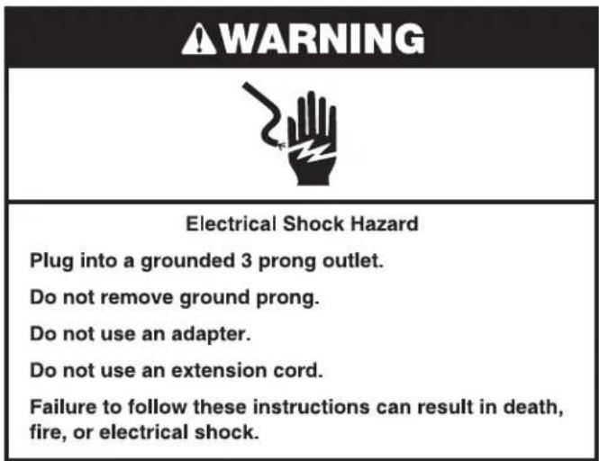
Failure to follow these instructions can result in death, fire, or electrical shock.
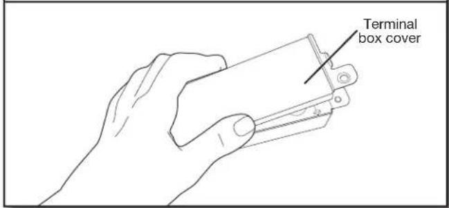
- Remove terminal box cover
text_image
Terminal box coverUsing 1/4" (6.4 mm) nut driver remove the screw holding the terminal box cover. Remove the cover by lifting it out of the box. Keep the cover for later use.
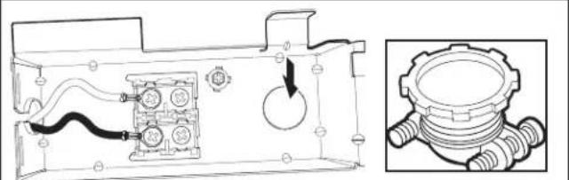
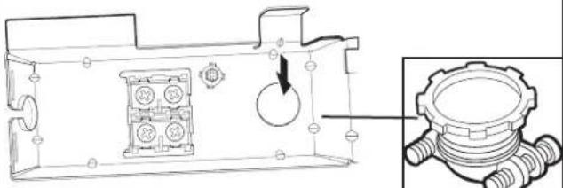
- Install strain relief
natural_image
Technical diagram of a mechanical assembly with internal components and a close-up view of a gear component (no text or symbols)Install a UL Listed/CSA Approved metallic strain relief. Make sure screw heads are facing up when tightening conduit nut. Strain relief is provided with the power cord kit.
If installing product using a Power Cord.
NOTE: Route drain hose out the back of unit before standing unit upright. Proceed to Step 18. If installing a product with direct wiring, wait until after Step 44 when the unit has been installed in the cabinet opening.
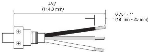
Suggested wire length relative to strain relief
text_image
4½" (114.3 mm) 0.75" - 1" (19 mm - 25 mm)Wiring configuration
text_image
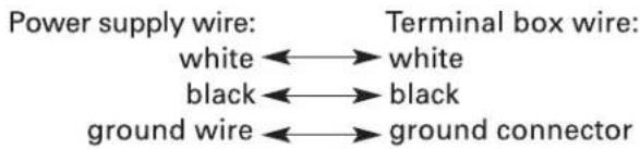
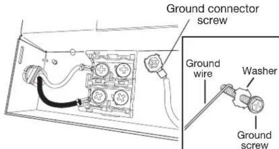
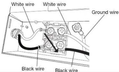
Power supply wire: white ←→ white black ←→ black ground wire ←→ ground connector Terminal box wire:- Connect ground wire
text_image
Ground connector screw Ground wire Washer Ground screwRoute power cord through strain relief in the back of the terminal box. Remove the ground connector screw on the raised floor inside the box and place it through the ring terminal of the green ground wire of power cord. Reattach and tighten the ground connector screw to the raised floor of the box.
- Secure cord or wire on strain relief
natural_image
Technical line drawing of a mechanical housing with internal components and a close-up inset showing a threaded component (no text or symbols)Tighten strain relief screws to secure cord.
- Connect remaining wires
text_image
White wire White wire Ground wire Black wire Black wireSelect UL Listed/CSA Approved power cord for the Dishwasher.
Power Cord Kit
Kit typically includes power cord, metallic strain relief, grommet. (Whirlpool Part Number Cord Kit - Straight - W11365011
Cord Kit - Right Angle - W11365014)
To connect wires with ring terminals, remove the screws from the terminal block, place the screw through the ring terminals, and reattach screws back into the terminal block.
To connect wires without ring terminals, remove the screws from the terminal block, push the wire ends under the screw heads, and tighten the screws.
NOTE: Pre-tinned wires should not be used when connecting to the terminal block.
- Reinstall terminal box cover and wires
natural_image
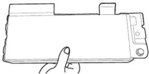
Line drawing of a hand holding a flat-screen camera (no text or symbols)Place wires inside terminal box. Replace the cover by inserting the hooks of the terminal cover into the slots in the floor of the terminal box and sliding the cover tight against the back wall where wires come in. Make sure wires are tucked inside the box and not pinched by the cover.
Put the terminal box back on the crossbar and push to the right so terminal box snaps into the plastic side member.
NOTES:
■Once the terminal box has been remounted on the dishwasher, tuck any excess length or slack over nearby components to help keep them off the floor.
■Route cord out the rear of the dishwasher so that it does not touch dishwasher motor or lower part of dishwasher tub.
■Do not plug cord into an outlet until instructed to do so.
■A maximum of 2 power cord supply conductors (12 AWG largest size) plus 1 grounding conductor are permitted in the terminal box.
IMPORTANT: NO ADDITIONAL CONNECTIONS OTHER THAN DISHWASHER POWER CONNECTION ARE TO BE MADE INSIDE THE DISHWASHER TERMINAL BOX.
INSTALL DOOR HANDLE (ON SOME MODELS)
text_image
Mounting stud Setscrew (in bottom of handle) Handle Hex keyIMPORTANT: Do not scratch the front panel during this procedure. If door panel has a protective film, peel film back past the point of the handle studs before installing handle. Handle is easiest to install while unit is on its back.
Remove the door handle and hex key from the packaging. Setscrews are already installed in the handle. Place handle on mounting studs with the setscrews facing down. Push the door handle tightly against the door. Insert the short end of the hex key into the setscrews. Tighten the setscrews 1/4 turn past snug.
Retain hex key with Installation Instructions.
PLACE DISHWASHER IN CABINET
WARNING
Excessive Weight Hazard
Use two or more people to move and install dishwasher.
Failure to do so can result in back or other injury.
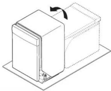
26. Stand dishwasher upright
natural_image
Technical line drawing of a mechanical component with a rotating arrow indicating rotation (no text or symbols)Using two or more people, stand the dishwasher up.
NOTE: Do not install kick plate until instructed to do so.
Dishwasher may fit tightly into cabinet opening. Do not remove insulation blanket—the blanket reduces the sound level.
IMPORTANT: Do not kink or pinch water line, drain hose, power cord, or direct wire between dishwasher and cabinet. Remove cardboard from under dishwasher (if used).
Install Foam Side Shields (on some models)
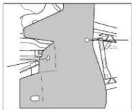
Install the foam side shields on both the right and left sides of the dishwasher. There are three attachment points on each side.
■Attachment 1: Locate the slit on the side shield and attach it to the hook on the side of the dishwashwe. (See figure 1)
natural_image
Pure technical diagram showing a mechanical or structural component without any text, numbers, or symbols.Figure: 1
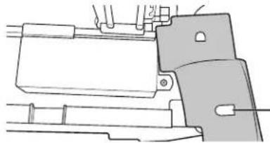
■Attachment 2: Use the other slit on the side shield and attach it to the hook on the front of the dishwasher. (See figure 2)
natural_image
Technical line drawing of a mechanical assembly with no visible text or symbolsFigure: 2
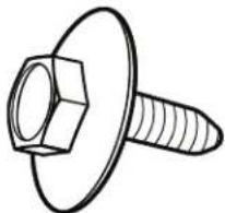
■Attachment 3: Align the rectangular hold in the side shield with the toe panel screw hole. Insert the Toe Panel Screw(see figure 3) and Loosely tighten it to hold it in place until the Toe Panel is installed.
natural_image
Line drawing of a bolt with hexagonal head and threaded shaft (no text or symbols)Figure: 3
■Tuck the lower ends of the side shields under the dishwasher. (See fugures 4 and 5)
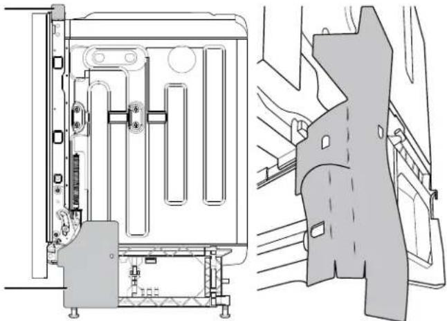
natural_image
Technical line drawing of a mechanical assembly with internal components and a close-up view of the same part (no text or symbols present)Figure: 4
Figure: 5
NOTE: Route water supply, drain hose, and power cord out the rear of the dishwasher. If your product has insulation around the bottom, route these lines through the slits in that insulation in the rear of the product.
27. Move dishwasher close to cabinet opening
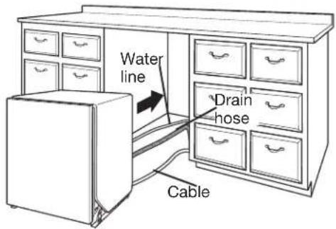
text_image
Water line Drain hose CableRoute the utilities through the holes in the cabinet, and pull the slack out at the same time as the dishwasher is pushed into the cabinet.
28. Route power cord
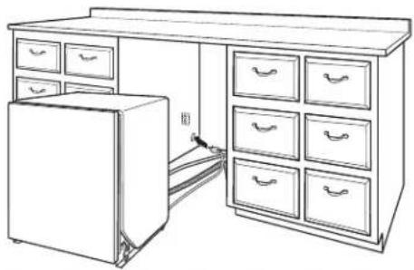
natural_image
Line drawing of a cabinet with drawers and an open refrigerator (no text or symbols)If using a power cord, make sure to route the end through hole in cutout before sliding dishwasher into the cabinet opening.
29. Secure insulation blanket
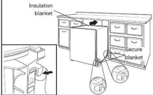
text_image
Insulation blanket Secure blanketNOTE: Make sure insulation blanket is secured at both left and right rear corners before pushing into cabinet opening to keep the blanket from bunching up in a tight fitting cabinet. The blanket can be secured by pulling the insulation down toward the bottom of the product and ensuring the hooks on the side members grab onto the slots in the insulation blanket.
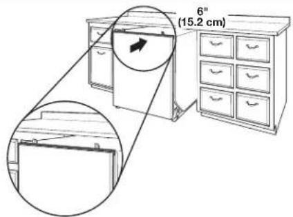
30. Move dishwasher all but 6" (15.2 cm) into cabinet opening
text_image
6" (15.2 cm)■Place Top Foam Sound Insulation (on some models)
- Snug the top foam into the slot on the top collar of the dishwasher as shown in the figure.
NOTE: Leave unit about 6" (15.2 cm) out from cabinet in order to install anchor brackets.
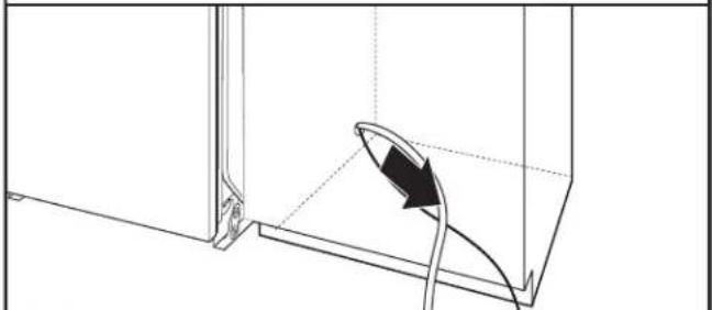
31. Pull slack from utilities
natural_image
Technical line drawing of a mechanical component with a curved arrow indicating direction (no text or symbols)NOTE: Pull slack out of utilities at the same time the dishwasher is pushed into the cabinet opening to avoid any kinks.
CUSTOM PANEL INSTALLATION (CUSTOM PANEL MODELS ONLY)
For custom panel installation, refer to the Custom Panel Installation Instruction Sheet included in the literature package. Complete custom panel installation before proceeding to the "Choose Anchor Attachment Method" section.
CHOOSE ANCHOR ATTACHMENT METHOD
IMPORTANT: The dishwasher must be secured to the cabinet as one of the final steps. Prepare the dishwasher for this by attaching the 2 brackets found in the parts bag to the dishwasher.
- For countertops that are wood, laminate or another similar surface: use Countertop Attachment and go to Step 32.
- For countertops that are marble, granite, or another hard surface: use Side Attachment and go to Step 33.
NOTE: If the gap between the top of the door and the underside of the counter top is tight (less than 1/4" [6.35 mm]), we suggest using Side Attachment to keep from scratching the User Interface or console with the anchor screws.
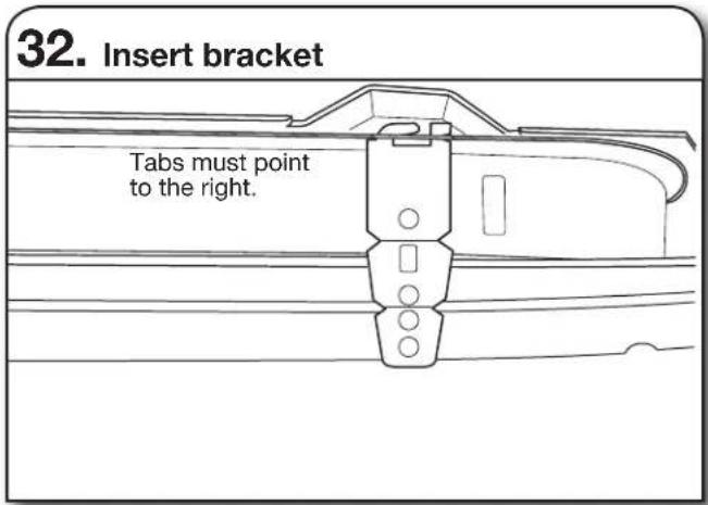
Countertop Attachment:
text_image
32. Insert bracket Tabs must point to the right.Remove the brackets from the package, and insert into the open slots on the left- and right-hand top of the dishwasher collar as shown.
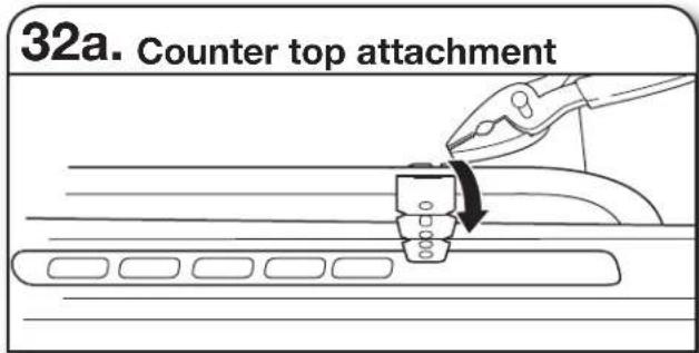
text_image
32a. Counter top attachmentUsing pliers, bend/twist tab to lock the brackets in place.
Side Attachment:
- Break end of bracket for side attachment
text_image
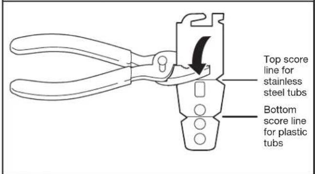
Top score line for stainless steel tubs Bottom score line for plastic tubsBreak off the end of the bracket along the scored line using pliers. Use sandpaper to smooth any burrs.
- Install bracket for Side Attachment
text_image
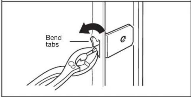
Bend tabsPush bracket into slot on the side of dishwasher, and bend tab in toward the side of the dishwasher so that it keeps the bracket in place. Repeat this step for the other side of the dishwasher.
NOTE: Install wood shims to the inside of the cabinets if the gap between the sides of the cabinet and the sides of the dishwasher are greater than 1/2" (1.3 cm) on each side.
NOTE: Do not attach the dishwasher. This will be done later.
FINAL INSTALLATION CHECK
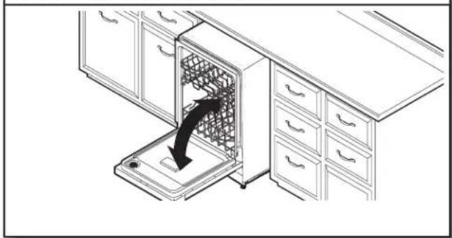
- Open and close door
natural_image
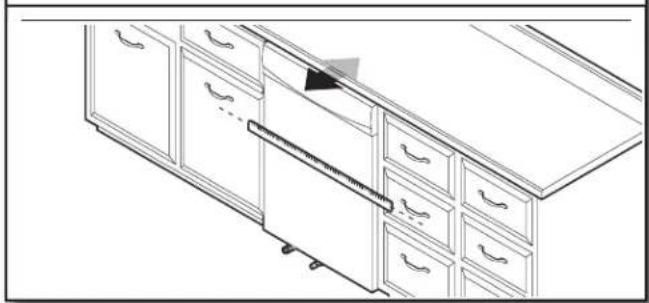
Line drawing of a kitchen appliance with a hand inserting into a drawer (no text or symbols)- Align front of dishwasher with front of cabinet doors
natural_image
Line drawing of a cabinet interior with drawers and a scroll, no text or symbols presentAlign front of dishwasher door panel with front of cabinet doors. You may need to adjust alignment to be even with your cabinets.
text_image
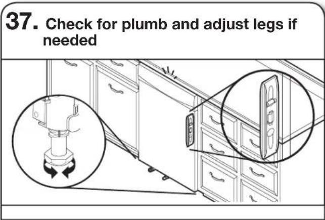
37. Check for plumb and adjust legs if needed■Check that leveling legs are firmly against the floor. Close and latch the door and place level against the front panel. Check that dishwasher is centered from front to back in the opening. If needed, adjust leveling leg until dishwasher is plumb. Repeat for other side of dishwasher.
■With dishwasher plum check that racks do not roll out on their own when you open the door. Adjust front level legs until racks no longer roll unless you pull them.
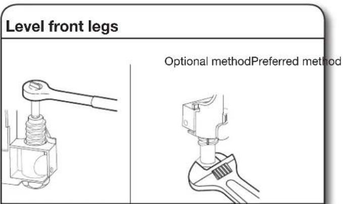
Helpful Tip: Push up on front of dishwasher to raise dishwasher off the ground to adjust front legs. With some installations, it may be easier to adjust the front leg using a 7 mm hex head socket or adjustable wrench. If the gap between the top of the door and the underside of the counter top is tight (less than 1/4" [6 mm]), we suggest side anchoring to keep from scratching the User Interface or console.
text_image
Level front legs Optional methodPreferred method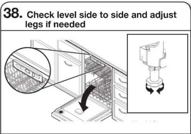
text_image
38. Check level side to side and adjust legs if neededPlace level against top front opening of tub. Check that dishwasher is level from side to side. If dishwasher is not level, adjust front legs up or down until dishwasher is level.
SECURE DISHWASHER IN CABINET OPENING
text_image
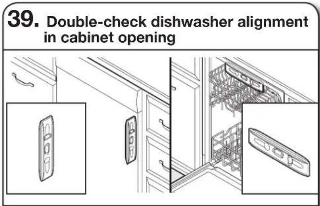
39. Double-check dishwasher alignment in cabinet openingCheck that dishwasher is still level front to back and side-to-side in the cabinet opening.
Open dishwasher door and place towel over pump assembly and spray arm of dishwasher. This will keep screws from falling into pump area when you are securing dishwasher to cabinet.
text_image
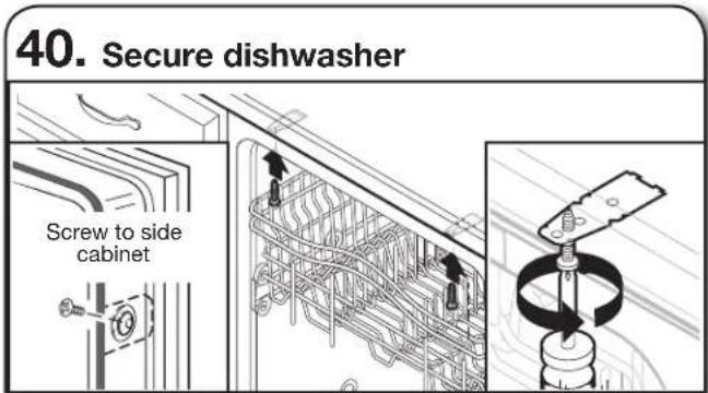
40. Secure dishwasher Screw to side cabinetOpen dishwasher door to prepare for securing the dishwasher to the countertop or side cabinet.
NOTES:
■The dishwasher must be secured to keep it from shifting when the door is opened or closed.
■Do not drop screws into bottom of dishwasher.
■Locate brackets installed in the "Choose Anchor Attachment Method" section, either on top or on the sides of the dishwasher.
■ If countertop anchoring: Secure dishwasher to the countertop with two Phillips-head screws (included).
■ If side anchoring: Drill 7/32" pilot holes in cabinet to avoid splitting the wood. Secure dishwasher to cabinet with two Philips-head screws (included). Remove second rack for easier access. See the Dishwasher Loading Tips section for instructions on how to remove the second rack if needed.
text_image
Technical diagram showing a mechanical assembly with labeled components and directional arrows indicating motion or force.IMPORTANT: Check that top of door does not contact screws, brackets, or countertop. If it does, adjust leveling legs or use the side attachment option.
- Check inner spacing
natural_image
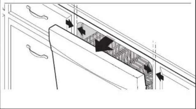
Architectural diagram of a cabinet with doorways and ceiling grilles (no text or symbols)Open door and check that space between dishwasher cabinet opening and tub is equal on both sides. If spacing is not equal, loosen bracket screws and shift tub. Tighten bracket screws.
43. Direct Wire Connection
To complete direct wire connection. Complete Steps 18 to 24 in this installation guide.
Once complete, return here to Step 44 to complete Product Installation.
CONNECT WATER LINE TO HOUSE SHUT-OFF VALVE
NOTE: If using a flexible braided hose, replace inlet hose after 5 years to reduce the risk of hose failure. Record hose installation or replacement dates on the hose for future reference.
- Attach water supply line
natural_image
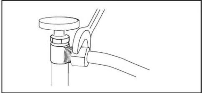
Line drawing of a pipe fitting with a valve and clamped cable (no text or symbols)Attach the water supply line (copper tubing or flexible braided line) to the hot water line using a connection configuration that is in compliance with local codes and ordinances. The water supply to the dishwasher should have a manual shut-off valve located under the sink. Turn water valve on after attaching water supply line.
CONNECT DRAIN HOSE
45. Connect drain hose
Connect drain hose to waste tee or waste disposer using one of the following options:
■Option A: Waste disposer – no air gap
■Option B: No waste disposer – no air gap
■Option C: Waste disposer – with air gap
■Option D: No waste disposer – with air gap
IMPORTANT: The drain hose connection of the disposer or a waste tee must be made before the drain trap and at least 20" (50.8 cm) above the floor where the dishwasher will be installed.
Helpful Tip: To reduce vibration of the hose, keep the hose away from the floor.
NOTE: Use the red clamp provided to connect the drain hose to the customer connection - plumbing or garbage disposal.
text_image
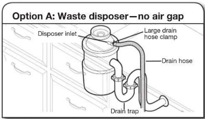
Option A: Waste disposer—no air gap Disposer inlet Large drain hose clamp Drain hose Drain trapHelpful Tip: Remove disposer knockout plug.
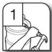
- Using a hammer and screwdriver, knock plug into disposer.
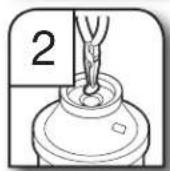
- Use needle-nose pliers to remove plug.
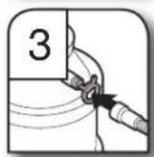
- Attach drain hose to disposer inlet with large drain hose clamp (provided). Use pliers to squeeze clamp open and move into position.
text_image
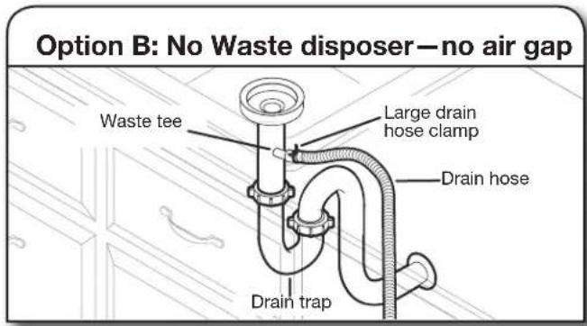
Option B: No Waste disposer—no air gap Waste tee Large drain hose clamp Drain hose Drain trap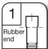
- Fit rubber end of drain hose to waste tee.
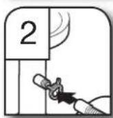
- Attach rubber end of drain hose to waste tee with a large drain hose clamp (provided). Use pliers to squeeze clamp open and move into position. If the drain hose was cut, use a 1½" to 2" (3.8 cm to 5.0 cm) screw-type clamp (not provided).
text_image
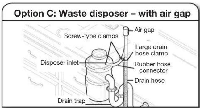
Option C: Waste disposer – with air gap Screw-type clamps Air gap Large drain hose clamp Disposer inlet Rubber hose connector Drain hose Drain trapHelpful Tip: Remove disposer knockout plug.
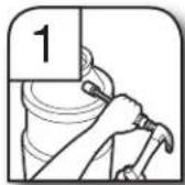
- Using a hammer and screwdriver, knock plug into disposer.
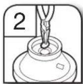
- Use needle-nose pliers to remove plug.

- Connect rubber end of drain hose to air gap.
NOTE: Do not cut ribbed section.
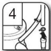
- Attach drain hose to air gap with large drain hose clamp (provided). Use pliers to squeeze clamp open and move into position. If the drain hose was cut, use a 1½" to 2" (3.8 cm to 5.0 cm) screw-type clamp (not provided).
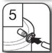
- Use a rubber hose (not provided) with screw-type clamps to connect from air gap to disposer inlet.
text_image
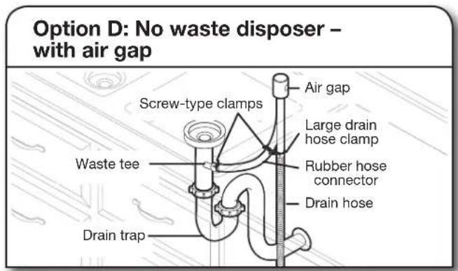
Option D: No waste disposer – with air gap Screw-type clamps Air gap Large drain hose clamp Waste tee Rubber hose connector Drain hose Drain trap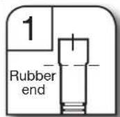
- Connect rubber end of drain hose to air gap.
NOTE: Do not cut ribbed section.
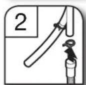
- Attach drain hose to air gap with large drain hose clamp (provided). Use pliers to squeeze clamp open and move into position. If the drain hose was cut, use a 1½" to 2" (3.8 cm to 5.0 cm) screw-type clamp (not provided)..
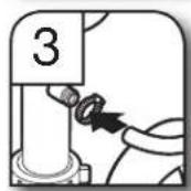
- Use a rubber hose (not provided) with screw-type clamps (not provided) to connect from waste tee to air gap.
COMPLETE INSTALLATION
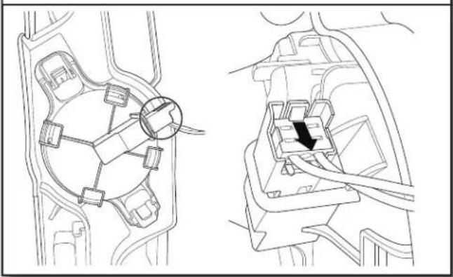
46. Reconnect float switch
natural_image
Technical line drawing of a mechanical component with no visible text or symbolsCheck that the power supply wire or cord does not touch dishwasher motor or the lower part of the dishwasher tub.
Reconnect float switch by aligning connector removed in Step 10 with the connector housing and pushing in until the locking tab is visible over the back of the connector.
47. Replace drip tray
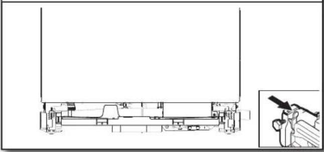
natural_image
Technical line drawing of a mechanical assembly with an inset showing a worker using a tool (no text or symbols present)NOTE: Before replacing the dip tray, ensure that there is no water present in the tray.
To replace drip tray, align with snaps in side members and push in toward unit. It is important that the black hoses are above the drip tray on both ends once it is pushed all of the way in.
text_image
WARNING Electrical Shock Hazard Plug into a grounded 3 prong outlet. Do not remove ground prong. Do not use an adapter. Do not use an extension cord. Failure to follow these instructions can result in death, fire, or electrical shock.48. Power supply cord—Plug into a grounded 3 prong outlet
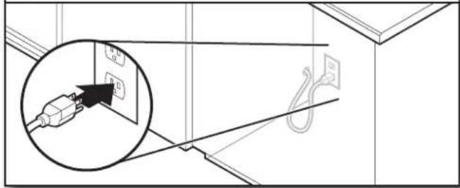
text_image
Diagram showing electrical connections with labeled components and a magnified inset highlighting a plug-in socket.Plug into a grounded 3 prong outlet.
49. Reconnect power
Reconnect electrical power at the fuse box or circuit breaker box.
NOTE: With the access panel off, start the dishwasher and allow it to complete the shortest Installation Cycle while checking unit for leaks. See instructions on this manual under Check Operations section.
CHECK OPERATION
■Read the dishwasher Quick Start Guide that came with your dishwasher.
■Check that all parts have been installed and no steps were skipped. Check that you have used all tools.
■Run the Installation Cycles as follows (Note that it can be beneficial to run this with the access panel removed in order to look for presence of water under the unit. If running in this state, the float switch wire MUST still be connected to the float switch.)
■If the dishwasher is not working properly, disconnect power or unplug dishwasher and refer to the "If Dishwasher Does Not Operate" section.
■Press any 3 keys (except Delay or Cancel) in the sequence 1-2-3-1-2-3-1-2-3 with no more than 1 second between key presses to enter the Installation cycle then press button #2.
■Close the door and the cycle will start.
■All LEDs turn on immediately upon receiving entry sequence.
■A tone may play depending on the model.
■The cycle will pause when the door is opened and resume when closed.
■No Start/Resume key press required to resume.
■The installation cycle may last several minutes.
■Press Cancel key to exit installation cyle mode. The product will exit this mode after 10 minutes or if power is removed from the appliance.
NOTE: It is normal for the drain pump to sound loud upon the first run since no water is present in the system.
| Numeric Display | All LEDs on 1 2 | 3 4 | 5(Some models 6 | 7 | ||||
| Approximate intervalTime 0:01 | 0:30(Maximum 5:00) 2:00 | 1:00(Maximum 5:00) | ||||||
| Machine Action | Fill 3.8L+Wash motor pulses | Wash+Dispenser(Middle spray pulses arm) | Wash+Fan(Celling spray arm) | Wash+Third Level Rack, If present in this model | Wash+Heater(Lower spray arm) | Drain Process | ||
| Pause | Initial Drain |
INSTALL ACCESS PANELS
50. Reinstall access panels and fasteners
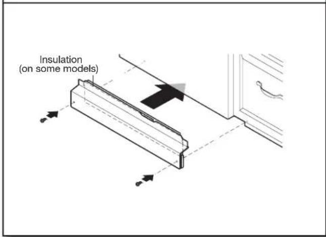
text_image
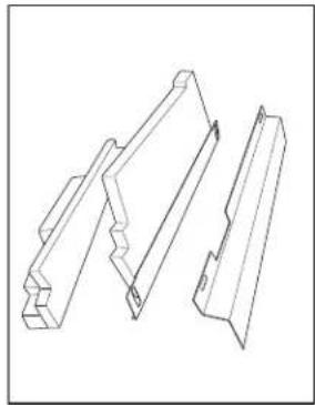
Insulation (on some models)Place the toe panel behind the access panel against the dishwasher leg. If insulation is included on this model, make sure insulation does not interfere with the float assembly. Push the access panel up toward the top of the product so that it hangs on the hooks on the plastic side members.
■Reinstall the toe/access panel assy. With side shield to go between the toe/access panel assembly and the side member. Align the rectangular slot in the foam and assembly the toe/access panel assembly to the unit using the screw.
NOTE: Remove film on door Score around door for easier removal.
natural_image
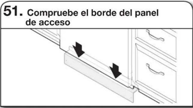
Technical line drawing of three mechanical bracket components (no text or symbols)51. Check access panel edge
natural_image
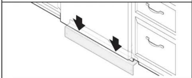
Diagram of a kitchen drawer with arrows indicating movement or force direction (no text or symbols)Check that the lower edge of the access panel touches the floor. Adjust if necessary.
52. Reinstall access panels
natural_image
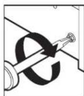
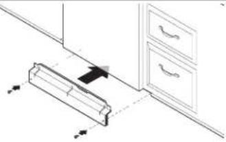
Isometric line drawing of a cabinet with drawers and door, no text or symbols presentUse a 5/16" nut driver to reinstall the screws through the holes in the access panels.
IF DISHWASHER DOES NOT OPERATE
First try the solutions suggested here to possibly avoid the cost of a service call.
■Has the circuit breaker tripped or the house fuse blown?
■Is the door closed tightly and latched?
■Has the cycle been set correctly to start the dishwasher?
■Is the water turned on?
■ Is the float switch wire under the product connected to the float switch?
■Make sure control lock is not on.
If none of these possible solutions work, please see the Quick Start Guide for service contact information.
Sanitize ou Sani (assainissement)
natural_image
Line drawing of a basket with multiple circular objects on top and a handle, no text or symbols presentStyle 1
natural_image
Cross-sectional diagram of a mechanical component with multiple teeth and central shaft (no text or labels)Style 2
natural_image
Technical line drawing of a structural frame with arrows indicating assembly or connection points (no text or symbols present)Style 1
natural_image
Technical line drawing of a mechanical assembly with no visible text or symbolsnatural_image
Isometric technical drawing of a 3D architectural structure with labeled components (no readable text or symbols)Porte-verres à pied
natural_image
Technical line drawing of a mechanical assembly with gears and housing (no text or symbols)natural_image
Illustration of a kitchen sink with a faucet and a cylindrical component, showing a downward arrow (no text or symbols)natural_image
Two line drawings of pliers, no text or symbols present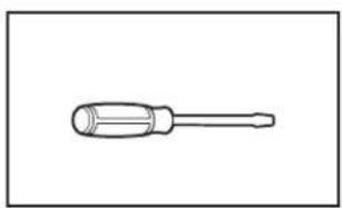
natural_image
Line drawing of a screwdriver with a cylindrical head and threaded shaft (no text or symbols)natural_image
Simple line drawing of a screwdriver (no text or symbols)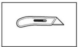
natural_image
Simple line drawing of a flat tool with a handle and central slot (no text or symbols)natural_image
Simple line drawing of a screwdriver with a cylindrical head and shaft (no text or symbols)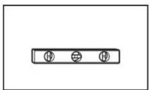
natural_image
Simple diagram with three circular symbols inside a rectangular box (no text or labels)natural_image
Line drawing of a measuring tape (no text or symbols)Petit niveau
natural_image
Simple line drawing of a double-ended wrench (no text or symbols)natural_image
Line drawing of an adjustable wrench (no text or symbols)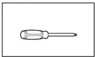
natural_image
Simple line drawing of a screwdriver (no text or symbols)natural_image
Simple line drawing of a flashlight with a handle and circular end cap (no text or symbols)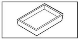
natural_image
Simple line drawing of a rectangular tray or container (no text or symbols)natural_image
Simple line drawing of a folded paper or plastic sheet (no text or symbols)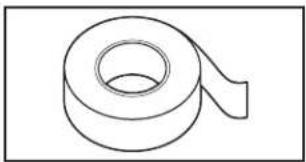
natural_image
Simple line drawing of a rolled-up adhesive tape (no text or symbols)natural_image
Two coiled rope or cord-like shapes, no text or symbols present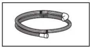
natural_image
Coiled cable or hose with two connectors, no text or symbols visiblenatural_image
Line drawing of a screw with two circular heads and a threaded shaft (no text or symbols)Tournevis cruciforme no 8 x 1/2 po (12,7 mm) (2)
Tuyau d'évacuation
natural_image
Two identical mechanical component diagrams with circular holes, no text or symbols presentnatural_image
Simple line drawing of a horizontal pipe or lever (no text or symbols)natural_image
Line drawing of a pipe fitting with a flanged end (no text or symbols)natural_image
Technical line drawing of a mechanical component with threaded ends and a central circular feature (no text or symbols)natural_image
Simple line drawing of a rolled-up adhesive tape (no text or symbols)natural_image
Simple geometric diagram with a square inside a rectangle (no text or symbols)natural_image
Simple line drawing of a mechanical component with a cylindrical shaft and curved base (no text or symbols)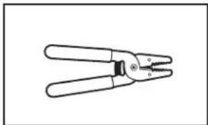
natural_image
Line drawing of a pair of pliers (no text or symbols)natural_image
Line drawing of a handheld electric drill (no text or symbols)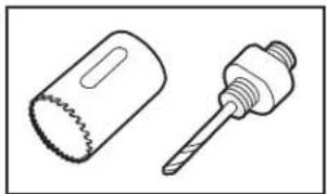
natural_image
Technical line drawing of two mechanical components: a cylindrical saw and a threaded screw (no text or symbols)natural_image
Line drawing of a coiled hose and a separate connector (no text or symbols)natural_image
Two interlocked rings with metal clips attached (no text or symbols)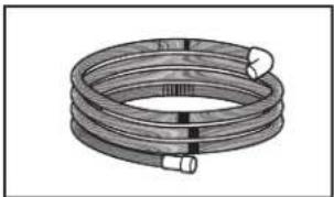
natural_image
Coiled industrial hose with flanged ends and connectors (no text or symbols visible)natural_image
Simple line drawing of a ring shape with no text or symbolsnatural_image
Simple line drawing of a coiled cable with wires (no text or symbols)National Fire Protection Association
1 Batterymarch Park
Quincy, MA 02169-7471
Il vous faut :
natural_image
Simple line drawing of a 3D rectangular block with a dashed top surface (no text or symbols)natural_image
Diagram of a mechanical assembly with a block and a curved component, no text or symbols presentnatural_image
Mechanical assembly diagram showing a tool inserted into a component with arrows indicating motion direction (no text or symbols present)natural_image
Technical diagram of a mechanical assembly with an inset showing a close-up of a component (no text or labels visible)natural_image
Pure mechanical diagram showing a circular component with internal components and mounting holes (no text or symbols)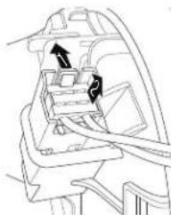
natural_image
Technical line drawing of a car interior showing structural components and directional arrows (no text or labels)natural_image
Line drawing of a cabinet with multiple drawers and drawers, no text or symbols presentnatural_image
Architectural cross-section diagram of a building facade with structural elements and directional arrows (no text or labels)natural_image
Simple line drawing of a coiled cable or tube (no text or symbols)natural_image
Line drawing of a flexible hose with two hexagonal connectors (no text or symbols)natural_image
Line drawing of a flexible hose with a flanged end cap and bolted joint (no text or symbols)BRANCHEMENT DU TUYAU DE REMPLISSAGE À LA VALVE DE DISTRIBUTION
text_image
Raccord coudénatural_image
Technical line drawing of a mechanical assembly with no visible text or symbolsnatural_image
Technical diagram of a mechanical assembly with internal components and a close-up view of a gear-like component (no text or symbols present)text_image
Power supply wire: white ←→ white black ←→ black ground wire ←→ ground connector Terminal box wire:natural_image
Technical line drawing of a mechanical housing with internal components and a close-up inset showing a threaded component (no text or symbols)natural_image
Line drawing of a hand holding a flat rectangular device (no text or symbols)natural_image
Diagram of a mechanical component with a rotating arrow indicating rotation (no text or symbols)natural_image
Pure technical line drawing of a mechanical part without any text, numbers, or symbolsIllustration : 1
natural_image
Technical line drawing of a mechanical assembly with no visible text or symbolsIllustration : 2
natural_image
Line drawing of a hexagonal bolt with a circular head (no text or symbols)Illustration : 3
natural_image
Technical line drawing of a mechanical device with internal components and external assembly (no text or symbols)natural_image
Line drawing of a refrigerator with drawers and an open refrigerator, no text or symbols presentnatural_image
Line drawing of a mechanical component with an arrow indicating direction (no text or symbols)natural_image
Line drawing of a kitchen appliance interior showing a close-up of a component being lifted by a tool, with no visible text or symbols.natural_image
Diagram showing a kitchen drawer with an inset close-up of the interior space, no text or symbols present.natural_image
Line drawing of a kitchen appliance interior showing front and side views with no text or symbolstext_image
Screw to side cabinettext_image
Diagram showing kitchen fixture installation with labeled components and directional arrows indicating motion or movement.natural_image
Architectural diagram showing door frame and ceiling structure with arrows indicating direction (no text or symbols)natural_image
Line drawing of a pipe fitting with a handle and valve (no text or symbols)natural_image
Technical line drawing of a mechanical component with internal parts and a highlighted section (no text or symbols)natural_image
Technical line drawing of a mechanical assembly with an inset showing a person using a tool (no text or symbols present)text_image
Diagram showing electrical installation with a plug inserted into a wall socket, highlighting the socket's internal structure.natural_image
Technical line drawing of three mechanical bracket components (no text or symbols)natural_image
Diagram of a kitchen drawer with arrows indicating movement or force direction (no text or symbols)text_image
Diagram illustrating door lock mechanism with labeled components and directional arrows indicating movementnatural_image
Illustration of a vintage computer case with a mesh basket and handle (no text or symbols)Estilo 1
natural_image
Cross-sectional illustration of a stainless steel mixing bowl with multiple spoons and a spoon (no text or labels)Estilo 2
natural_image
Technical line drawing of a structural frame with two arrows indicating points of interest (no text or symbols present)Estilo 1
natural_image
Diagram of a wire cage with arrows indicating direction, no text or symbols presentnatural_image
Technical line drawing of a mechanical assembly or lifting device (no text or symbols visible)natural_image
Technical line drawing of a mechanical assembly with gears and a grid base (no text or symbols)natural_image
Illustration of a kitchen sink with a faucet and a cylindrical container, showing a downward arrow indicating a drop (no text or symbols present)natural_image
Two line drawings of pliers, no text or symbols present
natural_image
Line drawing of a screwdriver with a cylindrical head and threaded shaft (no text or symbols)natural_image
Simple line drawing of a screwdriver (no text or symbols)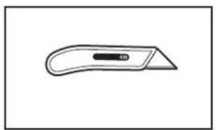
natural_image
Simple line drawing of a flat tool with a handle and central slot (no text or symbols)Destornillador Phillips Cuchillo para uso general
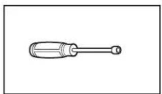
natural_image
Simple line drawing of a screwdriver with a cylindrical head and shaft (no text or symbols)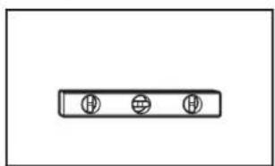
natural_image
Simple diagram with three circular symbols inside a rectangular box (no text or labels)Llave de cubo hexagonal o llave de tuercas de 5/16" (7,9 mm) y 1/4" (6,4 mm)
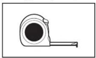
natural_image
Simple line drawing of a tape measure (no text or symbols)Nivel pequeño
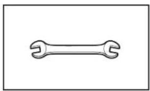
natural_image
Simple line drawing of a double-ended wrench (no text or symbols)natural_image
Line drawing of an adjustable wrench (no text or symbols)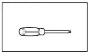
natural_image
Simple line drawing of a screwdriver (no text or symbols)Llave ajustable de 10" que se abra hasta 1 ^1/8 " (29 mm)
Destornilladores Torx ^† T20 y, si se instalan paneles frontales a la medida, Torx T15
natural_image
Simple line drawing of a flashlight with a bulb and handle (no text or symbols)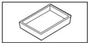
natural_image
Simple line drawing of a rectangular tray or container (no text or symbols)Linterna Bandeja Ilana
natural_image
Simple line drawing of a folded paper or plastic sheet (no text or symbols)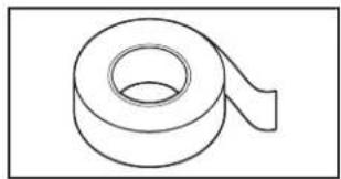
natural_image
Simple line drawing of a rolled-up tape or tape (no text or symbols)natural_image
Two coiled rope or wire loops, no text or symbols present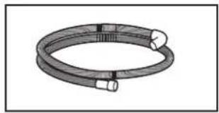
natural_image
Coiled cable or hose with two connectors, no text or symbols visiblenatural_image
Line drawing of a screw with two circular heads and a threaded shaft (no text or symbols)Manguera de desagüe
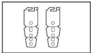
natural_image
Two identical mechanical component diagrams with circular holes, no text or symbols presentnatural_image
Simple line drawing of a horizontal pipe or lever (no text or symbols)natural_image
Line drawing of a pipe fitting with a flanged end (no text or symbols)natural_image
Technical line drawing of a mechanical component with threaded ports (no text or symbols)natural_image
Simple line drawing of a rolled-up adhesive tape (no text or symbols)natural_image
Two concentric squares, one larger and one smaller, with no text or symbols.natural_image
Simple line drawing of a mechanical component with a cylindrical shaft and curved base (no text or symbols)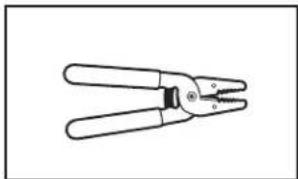
natural_image
Line drawing of a pair of pliers (no text or symbols)natural_image
Line drawing of a handheld electric drill (no text or symbols)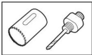
natural_image
Technical line drawing of two mechanical components: a cylindrical saw and a threaded screw (no text or symbols)Taladro inalámbrico Sierras perforadoras de 1/2" (12,7 mm), 3/4" (19 mm), and 1½" (38 mm)
natural_image
Line drawing of a coiled hose and a separate connector (no text or symbols)natural_image
Two interlocked rings with metal clips attached (no text or symbols)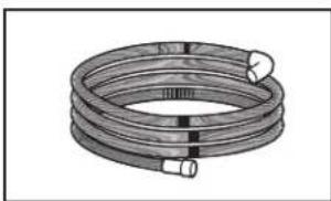
natural_image
Coiled industrial hose with flanged ends and connectors (no text or symbols visible)natural_image
Simple line drawing of a ring shape with no text or symbols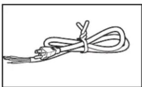
natural_image
Simple line drawing of a coiled cable or wire with connectors (no text or symbols)Pasacables de gabinete
National Fire Protection Association
1 Batterymarch Park
Quincy, MA 02169-7471
Usted debe tener:
natural_image
Simple line drawing of a rectangular box with a dotted top surface (no text or symbols)natural_image
Diagram of a mechanical assembly with a rectangular block and a curved component, showing motion direction (no text or symbols)natural_image
Mechanical assembly diagram showing a tool inserted into a housing with arrows indicating motion direction (no text or symbols present)natural_image
Technical diagram of a mechanical assembly with an inset showing a close-up of a component (no text or labels visible)natural_image
Technical line drawing of a mechanical component with internal parts and directional arrows (no text or symbols)natural_image
Line drawing of a cabinet with multiple drawers and drawers arranged in a row (no text or symbols)natural_image
Technical cross-section diagram of a mechanical assembly with no visible text or symbolsnatural_image
Simple line drawing of a coiled wire or tube, no text or symbols presentnatural_image
Line drawing of a coiled pipe with two hexagonal connectors (no text or symbols)natural_image
Line drawing of a coiled hose with a flanged end (no text or symbols)CONECTE LA MANGUERA DE LLENADO A LA VÁLVULA DE LLENADO
text_image
Technical diagram showing mechanical assembly with a zoomed-in detail labeled 'Codo' and an inset view of a component.natural_image
Technical line drawing of a mechanical assembly with no visible text or symbolsnatural_image
Technical line drawing of a mechanical assembly with internal components and a close-up inset showing a gear-like component (no text or symbols)text_image
Power supply wire: white ←→ white black ←→ black ground wire ←→ ground connector Terminal box wire:natural_image
Technical line drawing of a mechanical housing with internal components and a close-up inset showing a gear assembly (no text or symbols)natural_image
Line drawing of a hand holding a flat rectangular device (no text or symbols)natural_image
Technical line drawing of a mechanical component with a curved arrow indicating rotation (no text or symbols)natural_image
Pure technical diagram showing mechanical components without any text, numbers, or symbolsFigura: 1
natural_image
Technical line drawing of a mechanical assembly with no visible text or symbolsFigura: 2
natural_image
Line drawing of a bolt with hexagonal head and threaded shaft (no text or symbols)Figura: 3
natural_image
Technical line drawing of a mechanical device with internal components and external assembly (no text or symbols)Figura: 4
Figura: 5
natural_image
Line drawing of a simple kitchen cabinet with drawers and a refrigerator (no text or symbols)natural_image
Technical line drawing of a mechanical component with a curved arrow indicating direction (no text or symbols)natural_image
Line drawing of a kitchen appliance with a hand inserting into a drawer (no text or symbols)natural_image
Line drawing of a cabinet with drawers and a scroll, no text or symbols presentnatural_image
Line drawing of a kitchen appliance interior showing a close-up of a component being inserted, with no visible text or symbols.text_image
Technical diagram showing a device's internal structure and assembly process with magnified detail viewnatural_image
Technical line drawing of a cabinet interior with door holders and internal compartments (no text or symbols)text_image
Screw to side cabinettext_image
Technical diagram showing a kitchen fixture with labeled components and directional arrows indicating movement or assembly.natural_image
Architectural diagram showing door frame and staircase with directional arrows indicating movement (no text or symbols)natural_image
Line drawing of a pipe fitting with a valve and tubing (no text or symbols)natural_image
Technical line drawing of a mechanical assembly with a magnified inset showing a hand holding a tool (no text or symbols present)text_image
Diagram showing electrical connections with a plug inserted into a wall socket, including a magnified inset highlighting the plug's internal structure.natural_image
Technical line drawing of three mechanical bracket components (no text or symbols)