
GDT550PGRBK - Washing machine GE - Free user manual and instructions
Find the device manual for free GDT550PGRBK GE in PDF.

| Product Type | Built-in Dishwasher |
| Brand | GE |
| Model | GDT550PGRBK |
| Dimensions (W x D x H) | 61.0 cm x 61.0 cm x 87.6 cm (minimum opening) |
| Depth with handle | 67.9 cm max. |
| Power Supply | 120 V, 60 Hz, AC, 15 or 20 A |
| Water Connection | Hot water, 49-65 °C, pressure 1.4-8.3 bars |
| Capacity (number of place settings) | Not specified, standard 12-14 place settings |
| Installation Type | Built-in, undercounter or side mounting |
| Noise Levels | Not specified, typical < 50 dBA |
| Special Features | Bottle Jets (clips for bottlenecks), varied wash cycles |
| Tub Material | Stainless steel |
| Rack Type | Adjustable lower and upper rack |
| Maximum drain hose length | 4.88 m (16 ft) |
| Power cord length | 1.65 m or 2.41 m (depending on kit) |
| Weight | Not specified, approximately 45-55 kg |
| Sound Level | Not specified, typical 44-48 dBA |
| Water consumption per cycle | Not specified, typical 9-15 L |
| Safety | Grounding, automatic shut-off when door open, leak protection |
| Routine maintenance | Clean filters, check spray arms, use rinse aid |
| Replacement parts | Available: power cord kit, drain hoses, etc. |
| Repairability | Repairability index not provided, parts available via after-sales service |
Frequently Asked Questions - GDT550PGRBK GE
User questions about GDT550PGRBK GE
0 question about this device. Answer the ones you know or ask your own.
Ask a new question about this device
Download the instructions for your Washing machine in PDF format for free! Find your manual GDT550PGRBK - GE and take your electronic device back in hand. On this page are published all the documents necessary for the use of your device. GDT550PGRBK by GE.
USER MANUAL GDT550PGRBK GE
See your Owner's Manual for details on how to contact us regarding installation questions
BEFORE YOU BEGIN
Read these instructions completely and carefully.
⚠ WARNING
- Remove all power leading to the appliance from the circuit breaker or fuse box before beginning installation. Failure to do so can result in a risk of electrical shock.
- To reduce the risk of electric shock, fire, or injury to persons, the installer must ensure that the dishwasher is completely enclosed at the time of installation.
- The improper connection of the equipment grounding conductor can result in a risk of electric shock. Check with a qualified electrician or service representative if you are in doubt that the appliance is properly grounded. If house wiring is not 2-wire with ground, a ground must be by the installer. When house wiring is aluminum, be sure to use UL-Listed anti-oxidant compound and aluminum-to-copper connectors.
- To reduce the risk of electric shock, fire, or injury to persons, the installer should check to ensure that wires are not pinched or damaged, the house wiring is attached to the junction box bracket through a strain relief, and all electrical connections made at the time of install (wire nuts) are contained inside of the junction box cover.
ADVERTENCIA
Read and observe all WARNINGS and CAUTIONS shown throughout these instructions.
While performing installations described in this booklet, gloves, safety glasses or goggles should be worn.
IMPORTANT – Observe all governing codes and ordinances.
- Note to Installer – Be sure to leave these instructions for the consumer's and local inspector's use.
- Note to Consumer – Keep these instructions with your Owner's Manual for future reference.
- Skill Level – Installation of this dishwasher requires basic mechanical, electrical and plumbing skills. Proper installation is the responsibility of the installer. Product failure due to improper installation is not covered under the GE Appliances Warranty. See warranty information.
- Completion Time – 1 to 3 Hours. New installations require more time than replacement installations.
IMPORTANT – The dishwasher MUST be installed to allow for future removal from the enclosure if service is required. Care should be exercised when the appliance is installed or removed, to reduce the likelihood of damage to the power supply cord.
If you received a damaged dishwasher, you should immediately contact your dealer or builder.
Optional Accessories – See the Owner's Manual for available custom panel kits.
Your dishwasher is a water heating appliance.
CAUTION
Opening the door will cause the dishwasher to tip forward when it is
not fully installed. When opening the door prior to the dishwasher being fully installed, hold the top of the dishwasher securely with one hand and hold the door with the other hand. Gloves should be worn.
▲PRECAUCIÓN
READ CAREFULLY KEEP THESE INSTRUCTIONS
Installation Preparation
PARTS SUPPLIED:
• 2 Bottle Jets clips (on some models)
- Junction box cover
- #10 hex-head screw
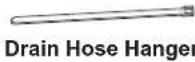
- Drain hose hanger
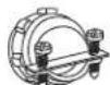
- Hose clamp
- 2 Plug buttons
• Toekick (pre-installed on some models)
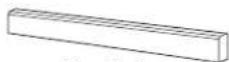
• 2 Tub trim pieces (on some models)
- Handle and 1/8" Allen wrench (on some models)
• 2 Mounting brackets for wood countertops or side cabinets
- 2 #8-18 x 5/8" Phillips special head screws, to secure dishwasher to underside of countertop or to side cabinets
• Insulation pieces (on some models)
• Literature, samples and/or coupons

Bottle
Jets clips
(on some
models)
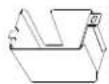
Junction Box Cover

10
Hex-Head Junction Box Screw 3/8" long
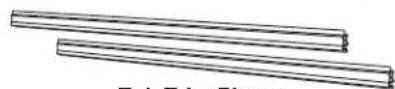
Tub Trim Pieces (on some models)

Plug Buttons
Toekick
Mounting Brackets

8 Phillips
Special Head Screws 5/8" long
Handle and 1/8" Allen wrench (on some models)
Insulation (on some models)

Literature
MATERIALS YOU WILL NEED:
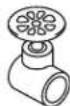
- 3/4" GHT (Garden Hose Thread) 90° elbow (including gasket) - with opposite end sized to fit Hot Water Line
- Thread seal tape
- UL-listed wire nuts (3)
- Masking tape
Materials For New Installations Only:
• Air gap for drain hose, if required
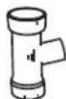
- Waste tee for house plumbing, if applicable
- Electrical cable or Power Cord Kit WX09X70910 (5' 5" long) or WX09X70911 (7' 11" long) depending on installation.
• Strain relief for electrical connection
- Hose clamps
• Hand shut-off valve (recommended)
- Hot Water Line—3/8" minimum, copper tubing (including ferrule, compression nut) or GE Appliances Part # WX28X326, flexible braided hose.
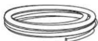
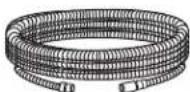
- WD24X10065 drain hose (12' long) or WD24X10062 drain hose (4' long), if needed.

Thread Seal Tape (if applicable)
Wire Nuts (3)

Masking Tape
Air Gap
Waste Tee
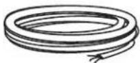
Electrical Cable (or Power Cord, if applicable)
Strain Relief

Hose
Clamps
Hand
Shut-Off
Valve
Hot Water Line
Optional -
12' Drain Hose - WD24X10065
4' Drain Hose - WD24X10062
TOOLS YOU WILL NEED:
• Phillips-head screwdriver
• 1/4" and 5/16" nutdriver
- 6" Adjustable wrench
- Level
• Carpenter's square
- Measuring tape
- Safety glasses
- Flashlight
- Bucket to catch water when flushing the line
- 15/16" socket
- Gloves
- Pliers
For New Installations Only:
- Tubing cutter
- Drill and appropriate bits
- Hole saw set
Phillips-Head
Screwdriver
1/4" and 5/16"
Nutdriver
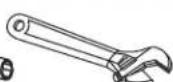
6" Adjustable Wrench
Flashlight
Level
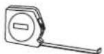
Measuring Tape
Safety Glasses
Flashlight
- The rough cabinet opening must be at least 24" deep, 24" wide and approximately 34-1/2" high from floor to underside of the countertop.
- The dishwasher must be installed so that drain hose is no more than 16' in length for proper drainage.
- The dishwasher must be fully enclosed on the top, sides and back, and must not support any part of the enclosure.
WARNING
To reduce the risk of electric shock, fire, or injury to persons, the installer must ensure that the dishwasher is completely enclosed at the time of installation.
ADVERTENCIA
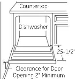
DISHWASHER HANDLE DIMENSION: The dishwasher door should be flush with the cabinet. For models with a handle, the total depth (with handle) is 26-1/4" max. depending on the model. Locate the Quick Specs document online for more dishwasher dimensions.
CLEARANCES: When installed into a corner, allow 2" min. clearance between dishwasher and adjacent cabinet, wall or other appliances. Allow 25-1/2" min. clearance from the front of the dishwasher for door opening.
DRAIN REQUIREMENTS
- Follow local codes and ordinances.
- Do not exceed 16' distance to drain.
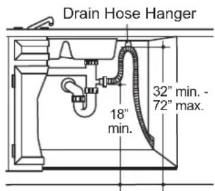
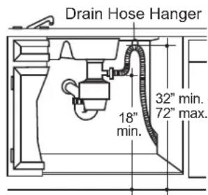
NOTE : Air gap must be used if waste tee or disposer connection is less than 18" above floor to prevent siphoning. DETERMINE DRAIN METHOD
The type of drain installation depends on the following questions.
- Do local codes or ordinances require an air gap?
- Is waste tee less than 18" above floor?
If the answer to either question is YES, Method 1 MUST be used.
- If the answers are NO, either method may be used.
CABINET PREPARATION - Drill a 1-1/2" diameter hole in the cabinet wall within the shaded areas shown in PREPARE DISHWASHER ENCLOSURE section for the drain hose connection. The hole should be smooth with no sharp edges.
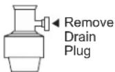
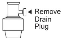
IMPORTANT – When connecting drain line to disposer, check to be sure that drain plug has been removed. DISHWASHER WILL NOT DRAIN IF PLUG IS LEFT IN PLACE.
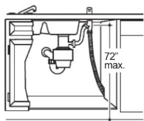
Method 1 – Air Gap with Waste Tee or Disposer An air gap must be used when required by local codes and ordinances. The air gap must be installed according to manufacturer's instructions.
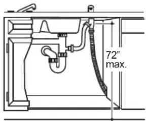
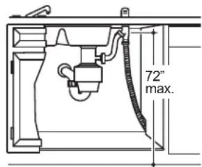
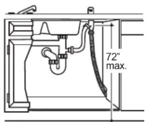
Method 2 – “High Drain Loop” with Waste Tee or Disposer
Tip: Avoid unnecessary service call charges. Always be sure disposer drain plug has been removed before attaching dishwasher drain hose to the disposer.
PREPARE ELECTRICAL WIRING
WARNING
Remove all power leading to the appliance from the circuit breaker or
fuse box before beginning installation. Failure to do so can result in a risk of electrical shock.
ADVERTENCIA
Be sure that the electrical connection and wire size are adequate and in conformance with the National Electric Code, ANSI/NFPA 70 – latest edition, and all local codes and ordinances.
This appliance must have:
- 120V, 60Hz, AC-only, 15-ampere or 20-ampere, fused electrical supply.
- Wiring must be 2 wire with ground and rated for 75^ (167°F).
- If the electrical supply does not meet the above requirements, call a licensed electrician before proceeding.
It is recommended to have:
- A circuit breaker or time-delay fuse.
• A properly grounded individual branch circuit.
Grounding Instructions—Permanent Connection
This appliance must be connected to a grounded metal, permanent wiring system, or an equipment-grounding conductor must be run with the circuit conductors and be connected to the equipment-grounding terminal or lead on the appliance.
Grounding Instructions-Power Cord Models
This appliance must be grounded. In the event of a malfunction or breakdown, grounding will reduce the risk of electric shock by providing a path of least resistance for electric current. This appliance is equipped with a cord having an equipment-grounding conductor and a grounding plug. The plug must be plugged into an appropriate outlet that is installed and grounded in accordance with all local codes and ordinances.
WARNING
The improper connection of the
equipment grounding conductor can
result in a risk of electric shock. Check with a qualified electrician or service representative if you are in doubt that the appliance is properly grounded. Do not modify the plug provided with the appliance; if it will not fit the outlet, have a proper outlet installed by a qualified technician.
ADVERTENCIA
WARNING
For models equipped with power cord: Do not modify the plug
provided with the appliance; if it will not fit the outlet, have a proper outlet installed by a qualified technician.
ADVERTENCIA
Cabinet Preparation & Wire Routing
- The wiring may enter the opening from either side, rear or the floor within the shaded area illustrated above in figure and defined in PREPARE DISHWASHER ENCLOSURE section.
- Cut a 1-1/2" maximum diameter hole to admit the electrical cable. Edges of hole should be smooth and rounded. Permanent wiring connections may pass through the same hole as the drain hose and hot water line, if convenient. If cabinet wall is metal, the hole edge must be covered with a bushing.
NOTE: Power cords with plug must pass through a separate hole in the cabinet.
Electrical Connection to Dishwasher
Electrical connection is on the right front of dishwasher.
- For permanent connections the cable must be routed as shown in figure. Cable must extend a minimum of 24" from the rear wall.
- For power cord connections, install a 3-prong grounding type receptacle in the sink cabinet rear wall, 6" min. or 18" maximum from the opening, 6" to 18" above the floor.
- Use only WX09X70910 (5' 5" long) or WX09X70911 (7' 11" long) Dishwasher Power Cord Kit. Do not use an extension cord or adapter plug with this appliance.
©
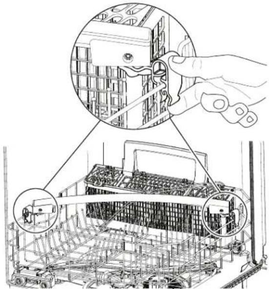
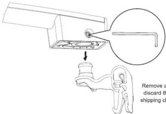
STEP 1 INSTALL HANDLE (on some models)
- Remove the packaged handle from the lower rack by pulling its shipping clips out and up.
natural_image
Technical illustration of a computer hardware setup with hand operating a key, showing internal components and assembly lines (no text or symbols)- Using the provided 1/8" Allen wrench, loosen the set screws to remove the shipping clips and discard them.
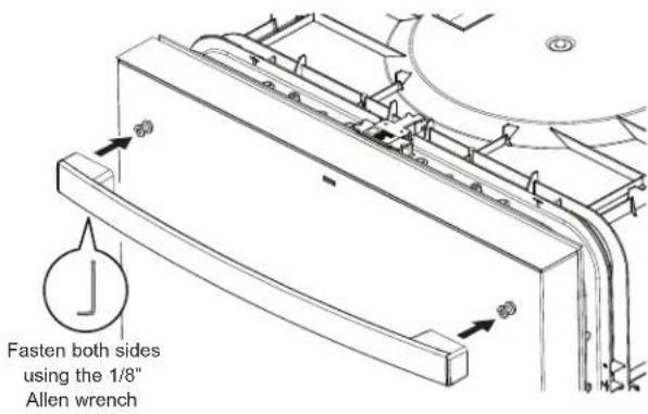
- Place the handle on the dishwasher door mounting fasteners, with the set screws on the bottom side, then tighten the set screws with the Allen wrench.
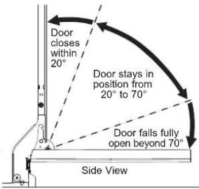
STEP 2 CHECK DOOR BALANCE
CAUTION
Opening the door will cause the dishwasher to tip forward when it is not fully installed. When opening the door prior to the dishwasher being fully installed, hold the dishwasher securely with one hand and h door with the other hand. Gloves should be
▲PRECAUCIÓN
To check the door balance, hold the top of the dishwasher firmly.
- Check the door balance by opening and closing the door.
- Door is properly balanced if, when opened, it self closes within 20^ from vertical, stays in position from 20^ to 70^ and falls fully open beyond 70^ .
NOTE: Springs are not adjustable.
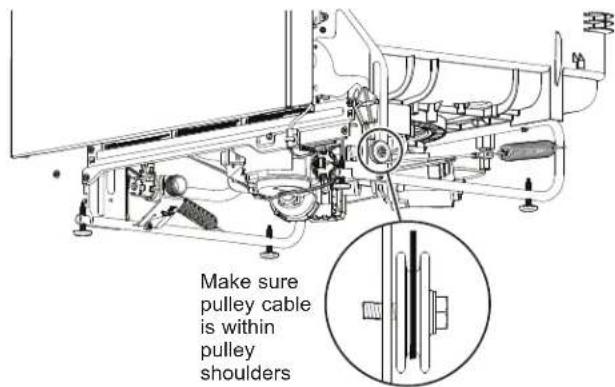
Tip: Make sure door opens and closes smoothly.
Check door opening and closing. If door does not open easily or falls too quickly, check spring cable routing. The cable is held in place by "shoulders" on the pulley. Check to be sure cable has not slipped over the pulley shoulders and is routed as shown.
Front View
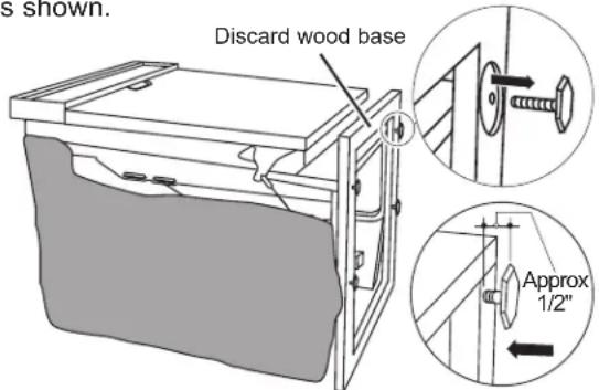
STEP 3 REMOVE WOOD BASE, INSTALL LEVELING LEGS
NOTE: Some models have an attached wood base.
CAUTION
Do not remove wood base until you are ready to install the dishwasher. The dishwasher will tip over when the door is opened if base is removed.
▲PRECAUCIÓN
IMPORTANT – Do not kick off wood base!
Damage will occur.
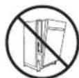
- Move the dishwasher close to the installation location and lay it on its back. NOTE: Do not place the dishwasher on its side.
- For models with an attached wood base, remove the 4 leveling legs on the underside of the wood base with a 15/16" socket wrench.
- Discard wood base.
- With a 15/16" socket wrench adjust leveling legs into the dishwasher frame, approximately 1/2" from frame as shown.
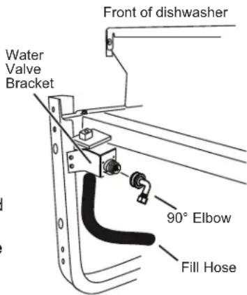
STEP 4 INSTALL 90° ELBOW
- Thread 3/4" GHT 90° elbow onto the water valve. Ensure rubber gasket is located between valve and elbow.
- Do not overtighten elbow. Water valve bracket could bend or water valve fitting could break.
- Position the end of the elbow to face the rear of the dishwasher.
STEP 5 POSITION WATER LINE AND HOUSE WIRING
- Position water supply line and house wiring on the floor of the opening to avoid interference with base of dishwasher and components under dishwasher.

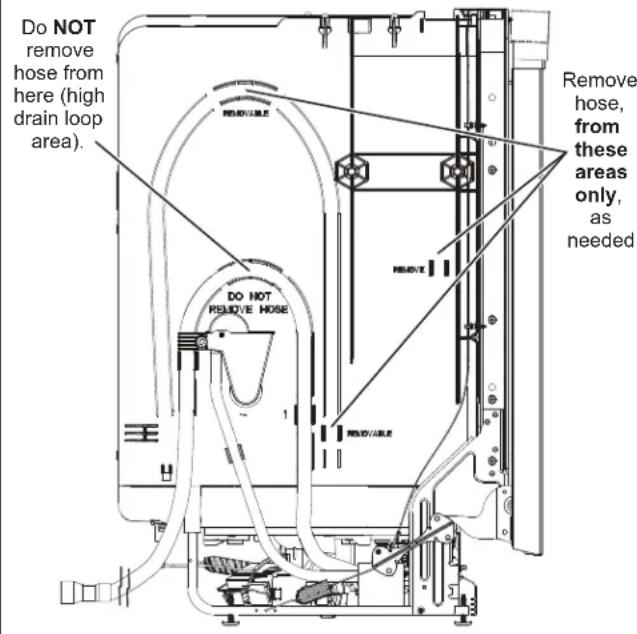
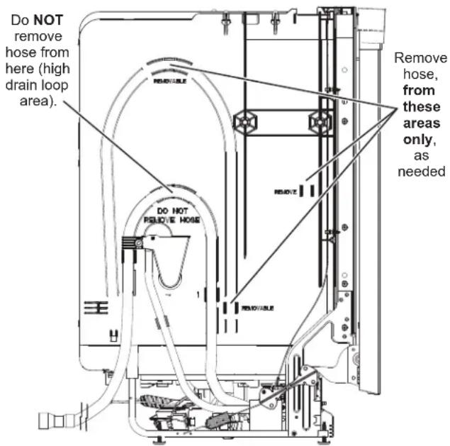
STEP 6 INSTALL DRAIN HOSE, THROUGH CABINET
- Detach the hose from the tub at locations indicated. NOTE: Do not remove high drain loop.
Dishwasher Installation
STEP 6 INSTALL DRAIN HOSE, THROUGH CABINET (CONT)
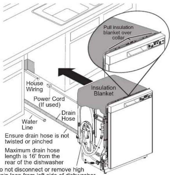
- Position dishwasher in front of cabinet opening. Insert drain hose into the hole in cabinet side. If a power cord is used, guide the end through a separate cabinet opening.
Tip: Prevent unnecessary service call charges for fill, drain or noise concerns.
Position utility lines so they do not interfere with anything under or behind the dishwasher.
Reposition the insulation blanket over the collar, as shown.
STEP 7 SLIDE DISHWASHER THREE-FOURTHS OF THE WAY INTO CABINET
IMPORTANT – Do not push against front panel with knees. Damage will occur.
- Grasp the sides of the front panel and slide dishwasher into the opening a few inches at a time.
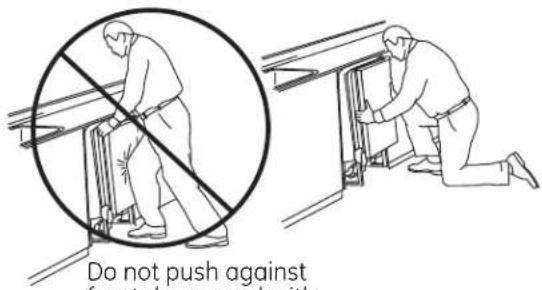
Do not push against front door panel with knee. Damage to the door panel will occur.
STEP 7 SLIDE DISHWASHER THREE-FOURTHS OF THE WAY INTO CABINET (CONT)
- As you proceed, pull the drain hose through the opening under the sink. Stop pushing when the dishwasher extends about 6 inches forward of adjacent cabinets.
- Make sure drain hose is not kinked under or behind the dishwasher.
- Make certain the house wiring, drain line and water line do not interfere with components under dishwasher.
STEP 8 INSTALL TRIM PIECES
In this step you will need the trim pieces set aside in Step 1.
Top Trim
(on some models)
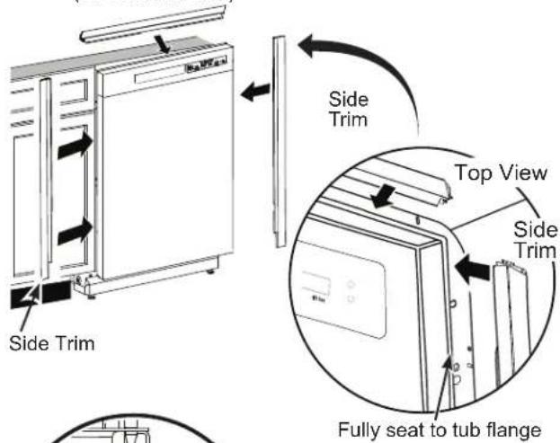
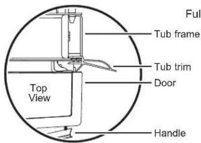
- Select the top trim piece and line up center to the top latch. Press the trim piece onto the tub flange moving from one side to the other.
- Select the left trim piece. Align top edge with the top trim and press it onto the left side of the tub flange moving from the top to the bottom. Repeat for the right side tub flange trim piece.
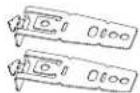
STEP 9 INSTALL MOUNTING BRACKETS
You will need the mounting brackets set aside in Step 1.
You must install the mounting brackets onto the dishwasher tub frame top OR sides prior to sliding the dishwasher into place under the countertop.
Install mounting brackets on top if the underside of countertop is wood or wood-like material that accepts screws:
Install the brackets by inserting the tabs through the slots on the tub frame as shown. NOTE: You may need to work the tabs through the slots.
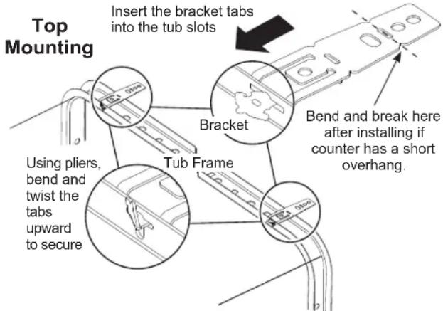
Using pliers, bend and twist the tabs upward to secure as shown.
IMPORTANT - After installing brackets and before closing the dishwasher door, adjust the brackets by bending them up as needed, so that they do not contact the top of the dishwasher door and cause damage.
- If you are installing the dishwasher under a counter with a short overhang, the countertop brackets may extend beyond the edge of the counter. If this is the case, remove the excess length by repeatedly bending the brackets at the front notch only until they break.
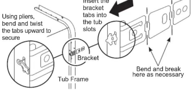
STEP 9 INSTALL MOUNTING BRACKETS (CONT.)
Install mounting brackets on sides if the countertop is granite or similar material that will not accept wood screws:
- Break off front portion of the bracket with pliers at the location shown prior to attaching to dishwasher.
- Install the brackets by inserting the tabs through the slots on the tub frame as shown. NOTE: You may need to work the tabs through the slots.
Using pliers, bend and twist the tabs to secure as shown.
Side Mounting
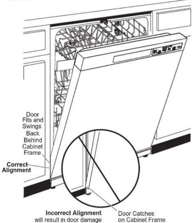
STEP 10 PUSH DISHWASHER INTO FINAL POSITION
- Check the tub insulation blanket, if equipped, to be sure it is smoothly wrapped around the tub. It should not be “bunched up” and it must not interfere with the door springs. If the insulation is “bunched up” or interfering with the springs, straighten and re-center the blanket prior to sliding the dishwasher into its final position.
- Slide the dishwasher into the final position by pushing on the sides of the door panel. Do not push or pull the door in a partially open or closed position when moving the dishwasher. Do not use a knee or push on the center of the panel. If you do, damage to the panel will likely result.
- The dishwasher is in the final position when the edges of the front panel are flush with the adjacent cabinets and the dishwasher is centered in the cabinet opening. Check that the dishwasher is squarely positioned in the cabinet opening at both the top and the bottom of the appliance prior to mounting to the cabinet.
IMPORTANT – Before opening the dishwasher door, be certain the edges of the dishwasher door panel are behind the face of the adjacent cabinet and not up against the cabinet face. Refer to figure below. If the dishwasher door is opened when the edge of the door is against the face of the cabinet, dishwasher door damage and cabinet damage will occur.
STEP 10 STEP10 DISHWASHER INTO FINAL POSITION (CONT.)
- Check dishwasher alignment prior to opening dishwasher door to prevent panel damage.
- Open and close the dishwasher door to be sure it operates smoothly, and does not rub on the adjacent cabinet.
Tip: Prevent unnecessary service charges for panel damage or wash performance.
Make sure utility lines are not trapped or crushed behind dishwasher. Crushed lines will restrict water flow.
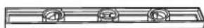
LEVEL DISHWASHER
IMPORTANT – Dishwasher must be level for proper dish rack operation, wash performance and door operation. The dishwasher must be leveled left to right and front to back. This ensures the dish racks will not roll in or out on their own, circulation water will flow to the pump inlet, and the door will close without hitting the side of the tub.
- Remove the lower dish rack and place a level on the door and lower rack track as shown in figure.
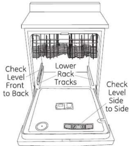
- Adjust the level of the dishwasher by individually turning the 4 legs on the bottom of the dishwasher as shown. Ensure all 4 legs are firmly in contact with the floor.
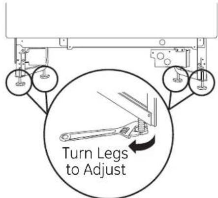
- The dishwasher is properly leveled when the level indicator is centered left to right and front to back. Also, the dishwasher door should close without hitting the side of the tub.
- Replace the lower rack.
Tip: Prevent unnecessary service charges. Verify dishwasher is leveled.
Pull the dish racks half way out. They should stay put. Open and close the door. The door should fit in the tub opening without hitting the side of the tub. If the racks roll on their own, or the door hits the side of tub, re-level the dishwasher.
STEP 12 POSITION DISHWASHER, SECURE TO COUNTERTOP OR CABINET
In this step you will need the 2 Phillips special head screws from the screws set aside in Step 1.
The dishwasher must be secured to the countertop or the cabinet sides. When the underside of the countertop is wood, use Method 1. Use Method 2 when the underside of the countertop is made of a material, such as granite, that will not accept wood screws.
IMPORTANT – Prevent door panel and control panel damage. Dishwasher must be positioned so the front panel and control panel do not contact the adjacent cabinets or countertop. The unit should be centered between the 2 cabinets. Mounting screws must be driven straight and flush. Protruding screw heads could scratch the door panel or control panel and interfere with door operation.
Method 1
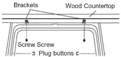
Secure dishwasher to underside of wood countertop.
- Re-check alignment of the dishwasher in the cabinet. Refer to Steps 12 and 13. Door panel and/or control panel must not hit cabinets or countertop.
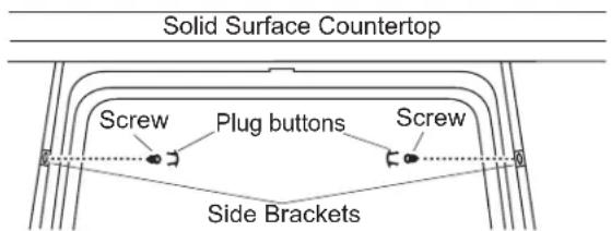
- Fasten the dishwasher to the underside of the countertop with the 2 Phillips special head screws. Refer to figure. Make certain screws are driven straight and flush to prevent panel damage.
- Plug buttons must be installed to ensure proper door to tub alignment. Install plug buttons to the side of the tub well in the holes provided.
Method 2
Secure dishwasher to cabinet sides.
- Recheck alignment of the dishwasher in the cabinet. Refer to Steps 12 and 13. Door panel and/or control panel must not hit cabinets or countertop.
- Fasten the dishwasher to the adjacent cabinets with the 2 Phillips special head screws provided. Refer to figure. Make certain screws are driven straight and flush to prevent panel damage. Do not screw into the cabinet face frame.
- Plug buttons must be installed to ensure proper door to tub alignment. Install plug buttons to the side of the tub in the holes provided.
STEP 12 POSITION DISHWASHER, SECURE TO COUNTERTOP OR CABINET (CONT.)
- Re-check that the dishwasher is squarely positioned in the cabinet at both the top and bottom of the appliance after mounting to the cabinets/countertop. Adjust if necessary.
- Confirm all leveling legs are in contact with the floor to prevent the dishwasher from rocking and ensure proper door and latch operation
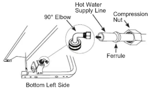
STEP 13 CONNECT WATER SUPPLY
Connect water supply line to 90° elbow.
If using a flexible braided hose connection:
- Attach nut to 90^ elbow using an adjustable wrench.
If using a copper tubing connection:
- Slide compression nut, then ferrule over end of water line.
- Insert water line into 90^ elbow.
- Slide ferrule against elbow and secure with compression nut.
IMPORTANT – Check to be sure that door spring and/or door spring cable do not rub or contact the fill hose or water supply line. Test by opening and closing the door. Re-route the water supply lines if a rubbing noise or interference occurs.
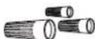
STEP 14 CONNECT DRAIN LINE
- The hose should have already been detached from the tub at locations indicated. NOTE: Do not remove high drain loop.
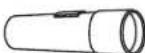
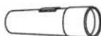
The molded end of the drain hose will fit 5/8" through 1" diameter inlet ports on the air gap, waste tee or disposer.
• Determine size of inlet port.
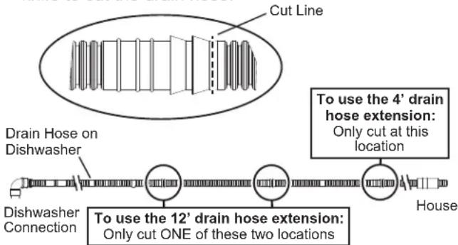
- Cut drain hose connector on the marked line, if required, to fit the inlet port.

- If a longer drain hose is required, you can purchase an extension drain hose - GE Appliances service part WD24X10062 (4' length) or WD24X10065 (12' length) which can be connected directly to the drain hose already attached to the unit. To use the extension, you must cut the drain hose provided with the unit as shown. Use a hose cutter or razor blade knife to cut the drain hose.
flowchart
graph LR
    A["Cut Line"] --> B["Drain Hose on Dishwasher"]
    B --> C["To use the 4' drain hose extension: Only cut at this location"]
    C --> D["House"]
    D --> E["To use the 12' drain hose extension: Only cut ONE of these two locations"]
    E --> F["To use the 12' drain hose extension"]
    F --> G["House"]
    style A fill:#f9f,stroke:#333
    style C fill:#ccf,stroke:#333
    style E fill:#cfc,stroke:#333
- TOTAL DRAIN HOSE LENGTH MUST NOT EXCEED 16' FROM THE REAR OF THE DISHWASHER FOR PROPER DRAIN OPERATION.

CONNECT DRAIN LINE (CONT.)
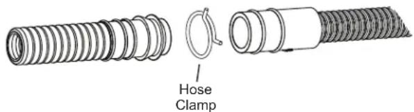
- Connect drain line to air gap, waste tee or disposer using the previously determined method. Secure hose with a hose clamp.
Method 1 – Air gap with waste tee or disposer
Waste Tee Installation
Disposer Installation
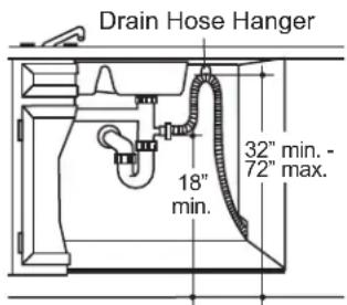
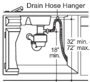
Method 2 – “High drain loop” with waste tee or disposer
With this method you will need the drain hose hanger set aside in Step 1.
Fasten drain hose to underside of countertop with the provided hanger.
Waste Tee Installation
Disposer Installation
IMPORTANT – When connecting drain line to disposer, check to be sure that drain plug has been removed. DISHWASHER WILL NOT DRAIN IF PLUG IS LEFT IN PLACE.
Tip: Avoid unnecessary service call charges for a no drain complaint.
Make sure excess drain hose has been pulled through the cabinet opening. This will prevent excess hose in the dishwasher cavity from becoming kinked or crushed by the dishwasher.
STEP 15 CONNECT POWER SUPPLY
If a power cord with plug is already installed proceed to Step 18.
WARNING
To reduce the risk of electric shock, fire, or injury to persons, the installer should check to ensure that wires are not pinched or damaged, the house wiring is attached to the junction box bracket through a strain relief, and all electrical connections made at the time of install (wire nuts) are contained inside of the junction box cover.
ADVERTENCIA
In this step you will need the junction box cover and the #10 Hex head screw from the screws set aside in Step 1.
- Secure house wiring to the back of the junction box with a strain relief as shown in the MATERIALS YOU WILL NEED section.
- Locate the 3 dishwasher wires, (white, black and green) with the stripped ends coming out of the AC jumper. Use UL-listed wire nuts of appropriate size to connect incoming ground to green, white to white and black to black.
- Install the junction box cover using #10 hex head screw. Check to be sure that wires are not pinched under the cover and that all wire nuts are inside the cover.
- Make sure that the junction box cover is resting on the mounting bracket.

NOTE: All ground screws, brackets and wires must remain intact.
STEP 16 PRETEST CHECKLIST
Review this list after installing your dishwasher to avoid charges for a service call that is not covered by your Warranty.
- Check to be sure power is OFF.
- Open door and remove all foam and paper packaging.
- Locate the Owner's Manual set aside in Step 1.
- Read the Owner's Manual for operating instructions.
- Check door opening and closing. If door does not open and close freely, check for proper routing of spring cable over pulley. If door drops or closes when released, adjust spring tension. See Step 2.
- Check to be sure that wiring is secure under the dishwasher, not pinched or in contact with door springs or other components. See Step 17.
- Check door alignment with tub. If door hits tub, level dishwasher. See Step 13.
- Check door alignment with cabinet. If door hits cabinet, reposition dishwasher. See Step 12.
- Pull lower rack out, about halfway. Check to be sure it does not roll back or forward on the door. If the rack moves, adjust leveling legs. See Step 13.
- Check that door spring does not contact water line, fill hose, wiring or other components. See Step 12.
- Verify water supply and drain lines are not kinked or in contact with other components. Contact with motor or dishwasher frame could cause noise.
- Turn on the sink hot water faucet and verify water temperature. Incoming water temperature must be between 120°F and 140°F. A minimum of 120°F temperature is required for best wash performance. See PREPARE HOT WATER LINE section.
- Add 2 quarts of water to the bottom of the dishwasher to lubricate the pump seal.
- Turn on water supply. Check for leaks. Tighten connections if needed.
- Remove protective film if present from the control panel and door.
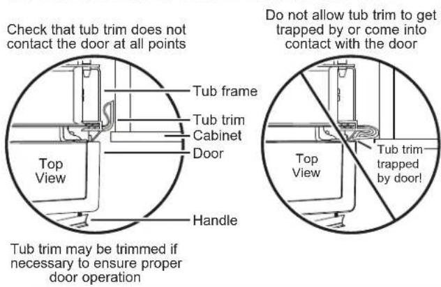
- Check that tub trim does not contact the door.
STEP 17 STEPH WASHER WET TEST
- Turn on power supply or plug power cord into outlet, if equipped.
- Select a cycle to run and push the Start/Reset pad.
- Ensure the door is latched. Dishwasher should start.
- Check to be sure that water enters the dishwasher. If water does not enter the dishwasher, check to be sure that water and power are turned on.
- Check for leaks under the dishwasher. If a leak is found, turn off power at the breaker, and then tighten water connections. Restore power after leak is corrected.
NOTE: A small amount of water may splash out of the fill funnel, on the right side of the tub, during the first use after installation. Splash-out is most likely to occur if there is air in the water supply line from new construction or if the valve has been closed for an extended time.
- Check for leaks around the door. A leak around the door could be caused by door rubbing or hitting against adjacent cabinets. Reposition the dishwasher if necessary. See Step 12.
- Press and hold the Start/Reset pad for 3 seconds to cancel the cycle. The unit will begin to drain. Check drain lines. If leaks are found, turn off power at the breaker and correct plumbing as necessary. Restore power after corrections are made. See Steps 6, 7, 8, 9 and 16.
- Open dishwasher door and make sure all of the water has drained. If not, check that disposer plug has been removed and/or air gap is not plugged. Also check drain hose to be sure it is not kinked underneath or behind dishwasher. See Step 16.
- Press Start/Reset pad once again and run dishwasher through another cycle. Check for leaks and correct if required.
- Repeat these steps as necessary.

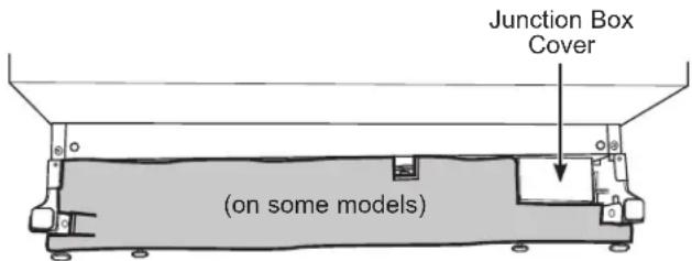
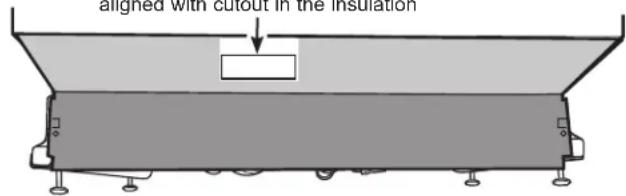
POSITION SOUND BARRIER AND INSULATION (on some models)
Skip this step if the sound barrier is assembled to the dishwasher.
- Locate the sound insulation package inside the dishwasher.
- Locate the control box.
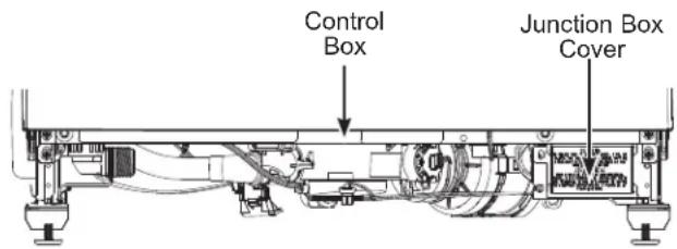
- Apply the insulation to the underside of the control box and flush with its front face as shown.
Insulation shown correctly placed along the bottom edge of the control box, the dishwasher bottom and flush with the front face.
If the insulation has an extension piece (on some models) follow these additional steps:
- Open door all the way, if the door doesn't stay fully open, adjust the insulation panel.
- Align the screw holes with the screw holes on the legs of the dishwasher.
- Ensure vent opening is not blocked by insulation.
Vent opening should be properly aligned with cutout in the insulation
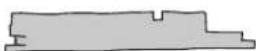
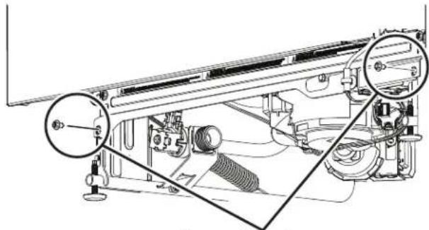
STEP 19 INSTALL TOEKICK
NOTE: On some models the toekick may come pre-installed.
- Remove the 2 screws installed on the front brace.
natural_image
Technical line drawing of a mechanical assembly with no visible text or symbolsRemove these two screws
- Place toekick against the legs of the dishwasher.
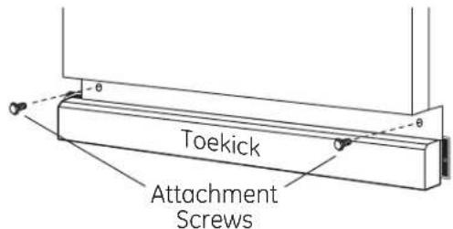
- Align the toekick with the bottom edge and make sure it is against the floor.
- Insert and tighten the 2 toekick attachment screws. The toekick should stay in contact with the floor.
NOTE: Be careful not to over-tighten the screws in the toekick.
- When reinstalling the toekick, on models with a sound barrier, ensure that the bottom edge is flush with the floor. Any excess material should be tucked up behind the outer door.
Tip: Reduce sound from under the dishwasher. Make sure toekick is against floor.
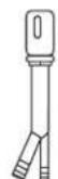
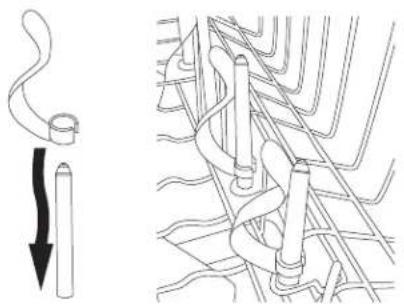
STEP 20 INSTALL BOTTLE JETS CLIPS (on some models)
- Locate the 2 Bottle Jets clips, depending on model, either in the silverware basket or the user bag. Install a clip over a Bottle Jets stem by slipping its clip end over the nozzel and pressing it down to the base.
natural_image
Diagram showing a cable being inserted into a pipe with a magnified view of the cable structure (no text or symbols)STEP 21 CHECK THE FOLLOWING
- Tub trim does not interfere with the door
- Dishwasher is square and level at both the top and bottom of the cabinet opening, with no twisting or distortion of the tub or door
- All 4 legs of the dishwasher are firmly in contact with the floor
- Drain hose is not pinched between the dishwasher and adjacent cabinets or walls
- Tub trim is fully seated on the tub flange
STEP 22 LITERATURE
- Be sure to leave complete literature package, these Installation Instructions and product samples and/or coupons with the consumer.
NOTE: Product improvement is a continuing endeavor. Therefore, materials, appearance and specifications are subject to change without notice.
Instructions D'Installation
natural_image
Technical illustration of a mechanical assembly with hand operating a tool, showing internal components and assembly lines (no text or symbols)natural_image
Two technical illustrations showing a person in different positions: one with a diagonal line and another with a kneeling figure (no text or symbols present)natural_image
Technical line drawing of a mechanical assembly with no visible text or symbolsnatural_image
Diagram showing a pipe being inserted into a cylindrical component and then coiled with coiled wires (no text or symbols present)ÉTAPE 21 VÉRIFIEZ LES POINTS SUIVANTS


- BEFORE YOU BEGIN
- ⚠ WARNING
- ADVERTENCIA
- CAUTION
- ▲PRECAUCIÓN
- READ CAREFULLY KEEP THESE INSTRUCTIONS
- Installation Preparation
- PARTS SUPPLIED:
- 10
- Phillips
- MATERIALS YOU WILL NEED:
- Materials For New Installations Only:
- TOOLS YOU WILL NEED:
- For New Installations Only:
- WARNING
- DRAIN REQUIREMENTS
- PREPARE ELECTRICAL WIRING
- This appliance must have:
- It is recommended to have:
- Grounding Instructions—Permanent Connection
- Grounding Instructions-Power Cord Models
- Cabinet Preparation & Wire Routing
- Electrical Connection to Dishwasher
- STEP 1 INSTALL HANDLE (on some models)
- STEP 2 CHECK DOOR BALANCE
- STEP 3 REMOVE WOOD BASE, INSTALL LEVELING LEGS
- STEP 4 INSTALL 90° ELBOW
- STEP 5 POSITION WATER LINE AND HOUSE WIRING
- STEP 6 INSTALL DRAIN HOSE, THROUGH CABINET
- Dishwasher Installation
- STEP 6 INSTALL DRAIN HOSE, THROUGH CABINET (CONT)
- STEP 7 SLIDE DISHWASHER THREE-FOURTHS OF THE WAY INTO CABINET
- STEP 7 SLIDE DISHWASHER THREE-FOURTHS OF THE WAY INTO CABINET (CONT)
- STEP 8 INSTALL TRIM PIECES
- STEP 9 INSTALL MOUNTING BRACKETS
- Install mounting brackets on top if the underside of countertop is wood or wood-like material that accepts screws:
- STEP 9 INSTALL MOUNTING BRACKETS (CONT.)
- Install mounting brackets on sides if the countertop is granite or similar material that will not accept wood screws:
- STEP 10 PUSH DISHWASHER INTO FINAL POSITION
- STEP 10 STEP10 DISHWASHER INTO FINAL POSITION (CONT.)
- LEVEL DISHWASHER
- Tip: Prevent unnecessary service charges. Verify dishwasher is leveled.
- STEP 12 POSITION DISHWASHER, SECURE TO COUNTERTOP OR CABINET
- Method 1
- Method 2
- STEP 12 POSITION DISHWASHER, SECURE TO COUNTERTOP OR CABINET (CONT.)
- STEP 13 CONNECT WATER SUPPLY
- STEP 14 CONNECT DRAIN LINE
- Method 2 – “High drain loop” with waste tee or disposer
- STEP 15 CONNECT POWER SUPPLY
- STEP 16 PRETEST CHECKLIST
- STEP 17 STEPH WASHER WET TEST
- POSITION SOUND BARRIER AND INSULATION (on some models)
- STEP 19 INSTALL TOEKICK
- STEP 20 INSTALL BOTTLE JETS CLIPS (on some models)
- STEP 21 CHECK THE FOLLOWING
- STEP 22 LITERATURE
- Instructions D'Installation
- ÉTAPE 21 VÉRIFIEZ LES POINTS SUIVANTS
Brand : GE
Model : GDT550PGRBK
Category : Washing machine