
GXRV10ABL - Water filter GE - Free user manual and instructions
Find the device manual for free GXRV10ABL GE in PDF.

| Product Type | Reverse Osmosis Filtration System |
| Brand | GE |
| Model | GXRV10ABL |
| Dimensions (H x W x D) | 40.64 x 43.18 x 15.24 cm |
| Tank Capacity | 1.3 gallons (4.9 L) |
| Water Production | Up to 10 gallons (38 L) per day |
| Required Water Pressure | 40-125 psi (2.8-8.6 bar) |
| Allowable Water Temperature | 4-38 °C (40-100 °F) |
| Allowable Water pH | 4-10 |
| Maximum Total Dissolved Solids (TDS) | 2000 ppm |
| TDS Reduction | 92% (new membrane) |
| Pre-filter and Post-filter | Carbon Block Cartridge (FX12P) |
| RO Membrane | Thin Film Polyamide (FX12M) |
| Bacteria Reduction | 99.95% |
| Automatic Shut-off | Yes |
| Maximum Recommended Hardness | 10 gpg (at pH 6.9) |
| Maintenance | Replace cartridges every 6 months; disinfect after replacement |
| Replacement Parts | FX12P (pre/post-filter), FX12M (membrane), flow restrictor, screen |
| Certification | NSF/ANSI 58 |
| Warranty | 1 year parts and labor |
Frequently Asked Questions - GXRV10ABL GE
User questions about GXRV10ABL GE
0 question about this device. Answer the ones you know or ask your own.
Ask a new question about this device
Download the instructions for your Water filter in PDF format for free! Find your manual GXRV10ABL - GE and take your electronic device back in hand. On this page are published all the documents necessary for the use of your device. GXRV10ABL by GE.
USER MANUAL GXRV10ABL GE
Safety Instructions 2
Operating Instructions
About the RO System 4,5
Specification Guidelines 3
Care and Cleaning
Cartridge Replacement .6,8
RO Cartridge Replacement
Procedure, Including
Sanitization .6-9,18
Installation Instructions
Before Beginning Installation . . .11
Important Recommendations . . .10
Step-by-Step Instructions 12-18
Checklist. 18
Drain Connections 13, 14
Faucet Drain Tubing and
Water Supply Tubing 16
Faucet Installation 15
Feed Water Supply 12
System Assembly 17
Tools and Materials Required 10
Troubleshooting Tips 19
Consumer Support
Consumer Support . . . .Back Cover
Parts List/Catalog 20, 21
Product Registration 2
Warranty 23

GXRV10ABL is Tested and
Certified by NSF International
against NSF/ANSI Standard 58
for claims specified on the
Performance Data Sheet.
Write the model and serial numbers here:
Model #
Serial #
You can find them on the sump bracket.
Owner's Manual and Installation
GXRV10ABL01
Osmose Inversée
For your safety, the information in this manual must be followed to minimize the risk of property damage or personal injury.

SAFETY PRECAUTIONS
Check with your state and local public works department for plumbing and sanitation codes. You must follow these guidelines as you install the Reverse Osmosis system. Using a qualified installer is recommended.
If house water pressure is over the maximum (125 pounds per square inch), install a pressure reducing valve in the water supply line to the Reverse Osmosis system.
- Be sure the water supply conforms with the Specification Guidelines. If the water supply conditions are unknown, contact your municipal water company or your local health department for a list of contaminants in your area and a list of laboratories certified by your state to analyze drinking water.
WARNING: Before using the Reverse Osmosis system for the first time, the system must be purged. The Reverse Osmosis cartridge contains a food grade preservative that must be purged from the system. The preservative will give product water an unpleasant taste and odor.
This product reduces fluoride in drinking water. Please consult your dentist if you have questions.
WARNING: Do not use with water that is microbiologically unsafe or of unknown quality without adequate disinfection before or after the system. Systems certified for cyst reduction may be used on disinfected water that may contain filterable cysts. This Reverse Osmosis unit contains a replaceable membrane cartridge treatment component critical for effective reduction of Total Dissolved Solids. The water should be tested periodically to verify that the system is performing satisfactorily. This system is acceptable for treatment of influent concentrations of no more than 27mg / L nitrate and 3mg / L nitrite in combination measured as N and is acceptable for nitrate/nitrite reduction only for water supplies with a pressure of 280kPa (40 psig) or greater.
This system shall only be used for arsenic reduction on chlorinated water supplies containing detectable residual free chlorine at the system inlet. Water systems using an in-line chlorinator should provide a one-minute chlorine contact time before the RO System.

PROPER INSTALLATION AND MAINTENANCE
This Reverse Osmosis system must be properly installed and located in accordance with the Installation Instructions before it is used.
Install or store where it will not be exposed to temperatures below freezing or exposed to any type of weather. Water freezing in the system will damage it. Do not attempt to treat water over 100^ .
- Do not install on HOT WATER. The temperature of the water supply to the Reverse Osmosis system must be between the minimum of 40^ and the maximum of 100^ . See the Specification Guidelines.
- Do Not open the water supply valve until the pipes have been flushed.
Extended non-use of the Reverse Osmosis system. If the system is not used for one week or more, open the RO water faucet, allow the system to drain. Close the RO water faucet and allow the system to regenerate the water supply.
WARNING: Discard all unused parts and packaging material after installation. Small parts remaining after the installation could be a choke hazard.
- Sanitize upon installation of the Reverse Osmosis system and after servicing inner parts, including replacement of prefilter, postfilter and Reverse Osmosis cartridge. It is important to have clean hands while handling inner parts of the system. See the Sanitizing the Reverse Osmosis System section.
This Reverse Osmosis system contains a replaceable treatment component critical for effective reduction of total dissolved solids. This product water shall be tested periodically to verify that the system is performing satisfactorily. See the About the Water Test Kit section.

READ AND FOLLOW THIS SAFETY INFORMATION CAREFULLY.
SAVE THESE INSTRUCTIONS
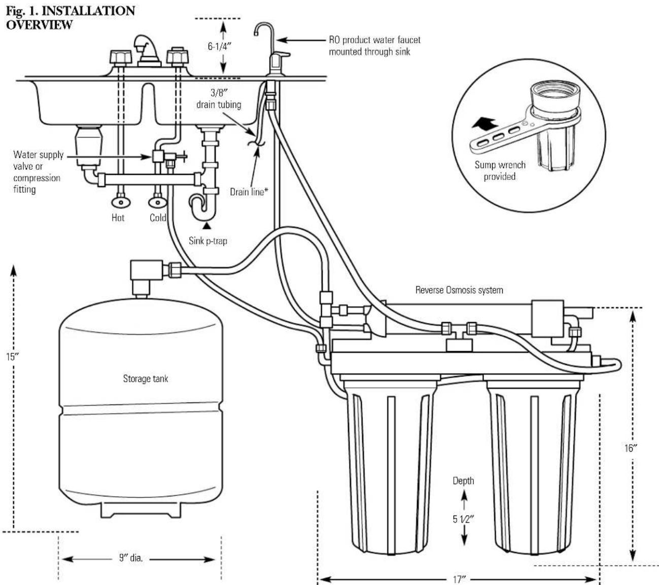
Product - height 16" width 17" depth 6"
The system makes a good supply of drinking water each day. How much it will make depends primarily on these things...
Feed water pressure limits—pounds per square inch (psi) 40-125
Feed water temperature limits-minimum/maximum degrees F. 40-100
Maximum Total Dissolved Solids (TDS) parts per million (ppm) 2000
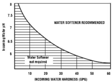
Maximum water hardness @ 6.9 pH recommended to optimize membrane life—grains per gallon (gpg) 10
For water with hardness greater than 10 grains (at 6.9pH the use of a softener is recommended. Failure to install a water softener will reduce the life of the Reverse Osmosis membrane. See chart for additional information on the possible need for a water softener.
Maximum iron, manganese, hydrogen sulfide (ppm) <0.1
Chlorine in water supply . Allowable
Feed water pH limits (pH) 4-10
Product (quality) water, 24 hours—gallons. 10.0^a
Process water per gallon of product water, 24 hours—gallons 5
Percent rejection of TDS (new membrane) .92a
Cyst reduction 99.95%
Storage tank capacity-gallons 1.3
Automatic shutoff control .yes
Prefilter and postfilter (FX12PA) Carbon Block
Reverse Osmosis membrane (FX12M) Thin Film Polyamid
Dimensions (inches) height 16" width 17" depth 6"
a. Tested by NSF International according to ANSI/NSF Standard 58 has given 7.1 GPD. Source: water test parameters are 50 psig, 77^ , pH of 7.5± 0.5 and 750~ppm total dissolved solids.
b. Removed (maximum of 2.0~ppm ) by the Reverse Osmosis prefilter. REGULAR MAINTENANCE IS REQUIRED. Chlorine will destroy the Reverse Osmosis membrane.
c. If house water pressure is over 125 psi, install a pressure reducing valve in the water supply line. If house water pressure is under 40 psi, install a Reverse Osmosis booster pump (contact your local plumbing supply company).
About the reverse osmosis system.
What the Reverse Osmosis System Does
Reverse Osmosis removes Total Dissolved Solids (TDS) and organic matter from water by diffusing it through a special membrane. The membrane separates minerals and impurities from the water and they are flushed to the drain. High quality product water goes directly to the drinking water faucet or to the storage tank. The system makes a good supply of drinking water each day; see Specification Guidelines above. How much it makes depends on the feed water supply pressure, temperature and quality.
The carbon prefilter and postfilter are replaceable cartridges. The prefilter removes chlorine while also filtering sediments. The postfilter removes any other undesirable tastes and odors before you use the water.
Description of the Reverse Osmosis System
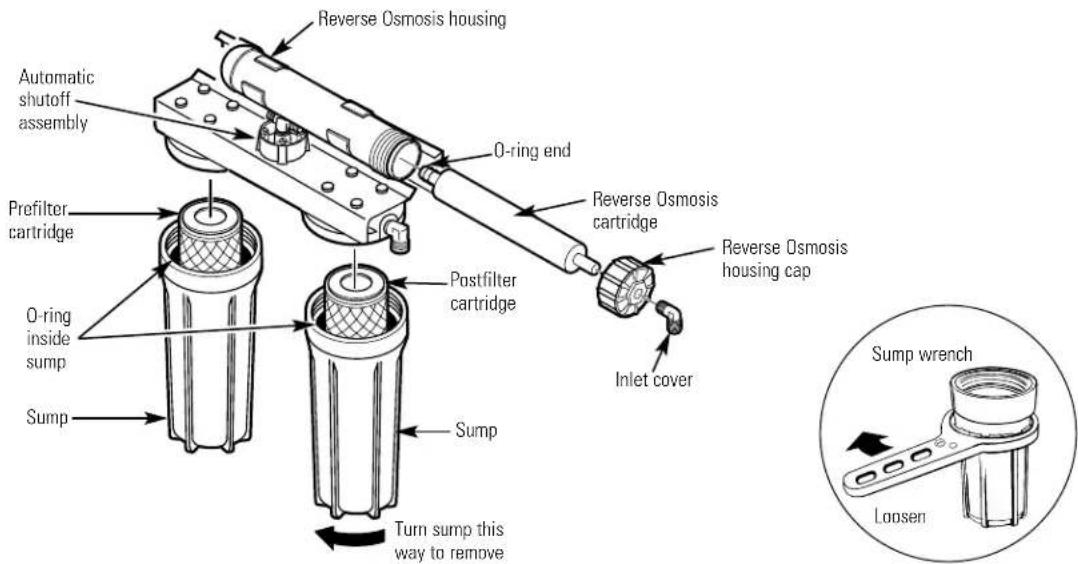
Prefilter—Water from the cold supply pipe is directed to the prefilter cartridge, which is inside the sump. The prefilter is a replaceable sediment cartridge containing activated carbon. The cartridge removes sand, silt, dirt, other sediments and up to 2.0~ppm of chlorine from the feed water. The prefilter reduces chlorine in the feed water because CHLORINE DESTroys THE REVERSE OSMOSIS MEMBRANE. Filtered, clean, chlorine-reduced water flows from the prefilter to the Reverse Osmosis cartridge.
Storage Tank—The storage area holds up to 1.3 gallons of product water. A diaphragm inside the tank keeps water pressurized, when the tank is full, for fast flow to the faucet when drinking water is needed.
Check Valve-A check valve is built into one end of the Reverse Osmosis housing. The check valve prevents a backward flow of product water from the storage area. A backward flow could cause the Reverse Osmosis membrane to rupture.
Automatic Shutoff Assembly-To conserve water, the drinking water system has an automatic shutoff. When the storage tank has filled to capacity and the drinking water faucet is closed, pressure closes the shutoff. Water flow to the Reverse Osmosis housing is shut off until drinking water is used again, and pressure drops in the Reverse Osmosis system.

WARNING: The reverse osmosis system contains a replaceable component critical to the efficiency of the system. Replacement of the reverse osmosis component should be with one of identical specifications, as defined by the manufacturer, to assure the same efficiency and contaminant reduction performance.
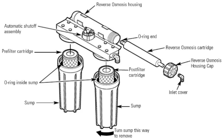
Reverse Osmosis Cartridge—The cartridge, inside the Reverse Osmosis housing, includes a tightly wound, special membrane. Water is forced through the cartridge where the membrane removes the dissolved solids and organic matter. High quality product water exits the Reverse Osmosis housing and goes to the storage tank. Reject water, with the dissolved solids and organic matter, leaves the housing and is discharged to the drain through 1/4'' tubing.
Postfilter—After leaving the storage area, but before going to the system faucet, product water goes to the postfilter which is inside the sump. The postfilter is also a replaceable sediment cartridge that contains activated carbon. Any remaining tastes, odors or sediments are removed from product water by the postfilter. Clean, high quality drinking water flows through the tubing and to the system faucet.
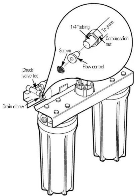
Flow Control—The flow control regulates the flow of water through the Reverse Osmosis cartridge at the required rate to produce high quality water. The control is located in the Reverse Osmosis housing drain port. A small, cone-shaped screen fits over the front end of the flow control to prevent clogging due to sediments in drain water. The flow control should be replaced each time the Reverse Osmosis membrane is changed.
Care and cleaning of the reverse osmosis system.
To obtain replacement filters, call toll-free GE Appliance Parts at 800-626-2002 (U.S.), 800-663-6060 (Canada-English), 800-361-3869 (Canada-French).
Prefilter/Postfilter Cartridge Replacement FX12P Carbon Block
Reverse Osmosis Cartridge Replacement FX12M Thin Film Polyamide

CAUTION: Before servicing the Reverse Osmosis system, close the water supply/saddle valve and open the RO water faucet. Allow the system to drain.
The Water Test Kit
This Reverse Osmosis system contains a replaceable treatment component, critical for effective reduction of Total Dissolved Solids (TDS). This product water shall be tested periodically to verify that the system is performing satisfactorily. Follow instructions included in the kit. Product water should be tested a minimum of every six months. A replacement test kit will be provided to you with the results of each test submittal.
Prefilter and Postfilter Cartridge Replacement
Follow the steps in the Sanitizing the Reverse Osmosis System section EXCEPT discard the old filters and replace with new filters.
Care and cleaning—RO cartridge replacement procedure, including sanitization.
Be sure you clean your hands with anti-bacterial soap before handling inner parts of the system.
Turn off the water supply valve to the Reverse Osmosis System. Open the RO water faucet and leave the storage tank open. Allow the water in the system to drain completely (this takes several minutes).
If the Reverse Osmosis Filtration system is connected to your icemaker, YOU MUST turn off the icemaker by raising the feeler arm before servicing the filter, changing the filters or purging the filtration system. Four hours after servicing your unit, lower the feeler arm to resume icemaking.
Pull the Reverse Osmosis System out away from the cabinet but do not disconnect any tubing. Place a dry towel under the Reverse Osmosis Unit to absorb water that will spill out during disassembly.
3 Unscrew inlet cover cap to open Reverse Osmosis housing.
Sanitizing the system is done with the Reverse Osmosis Cartridge and filter cartridges removed from the system.
Remove the Reverse Osmosis Cartridge from the housing by grasping the end of the cartridge with the clean pliers and pulling to the right.
NOTE: Water may be discolored when removing the cartridge—this is NORMAL. Place the cartridge in a clean plastic bag to protect the cartridge from damage until it is reassembled.
Reinstall the inlet cover, making sure the O-ring is in place.
6 Remove the POSTFILTER sump by turning it to the left using the sump wrench that was provided with the Reverse Osmosis System. Be careful when removing the sump because it is full of water. Remove the old filter cartridge from the sump and discard. Inspect the sump. Make sure the O-ring is seated in the top of the sump. Reinstall the sump (without the cartridge) to sanitize.
Remove the PREFILTER sump using the sump wrench and discard the old cartridge. Make sure the O-ring is seated in the top of the sump.
8 Sanitize the system.
CAUTION: Before adding the sanitizing agent, be sure to remove all cartridges as described above. Chlorine will destroy the Reverse Osmosis Cartridge. Sanitizing the system is done with the reverse osmosis cartridge and filter cartridges removed from the system.
Before reinstalling the PREFILTER sump, fill this sump with cold water to about 1^ from the O-ring. Add one ounce (two tablespoons) of ordinary 5.25% household chlorine bleach (Hilex, Clorox, etc.) and mix into the water. DO NOT ADD CHLORINE FIRST. Concentrated chlorine may damage plastic.
Carefully reinstall the sump onto the Reverse Osmosis System and tighten securely by hand.
Close the RO water faucet and turn on the water supply valve to the system. Allow system to fill for one minute.
NOTE: Various sounds will occur during the sanitizing. DO NOT USE WATER DURING SANITIZATION.
d Open the RO water faucet, locking the lever upward against the spout. Allow water to flow through the Reverse Osmosis system until all bleach odor is gone (approximately 20 minutes).
Turn off the water supply valve to the system, but leave the RO water faucet open. When the flow of water stops, proceed to Step 9.
9 Be sure hands have been cleaned with antibacterial soap. Repeat Steps 3-6 and 8b; however, reinstall the Reverse Osmosis Cartridge from the bag and the new PREFILTER and POSTFILTER instead of removing them. Lightly lubricate the inlet cover and sump O-rings with clean silicone grease only.
NOTE: The Reverse Osmosis Cartridge is notched and may need to be rotated during reinstallation for proper fit.
Turn on water supply valve to the Reverse Osmosis System and allow approximately four hours for the system to regenerate and stabilize. Check the system for leaks. The system may make some sounds during this period. This is normal.
Replace the "AA" alkaline batteries in the control box. Good batteries are necessary to ensure proper indicator light operation. Weak batteries may give a false indication. Batteries should be changed every six months.
Before first use after filter changes, purge the system by opening RO water faucet for one minute to remove any harmless carbon particles. If the system is connected to your refrigerator icemaker, reset the icemaker feeler arm to the on (down) position after the four-hour regeneration period.
Care and cleaning—RO cartridge replacement procedure, including sanitization.
Reverse Osmosis Cartridge Replacement
NOTE: When replacing the Reverse Osmosis cartridge, also install a new flow control and screen. See the Flow Control and Screen section.
If the Reverse Osmosis Filtration system is connected to your icemaker YOU MUST turn off the icemaker by raising the feeler arm before servicing the filter, changing the filters or purging the filtration system. Four hours after servicing your unit, lower the feeler arm to resume icemaking.
Be sure you clean your hands with anti-bacterial soap before handling inner parts of the system.
Turn off the water supply valve to the Reverse Osmosis system (turn clockwise) and open the RO water faucet. Allow the system to drain completely (this takes several minutes).
CAUTION: Failure to close the water supply valve will cause water to spray or run when sumps are removed.
Pull the Reverse Osmosis system out away from cabinet. Leave tubing connected. Place a dry towel under the Reverse Osmosis unit.
3 Unscrew inlet cover cap to open Reverse Osmosis housing.
Use pliers to pull the cartridge from the housing and discard the cartridge.
5 Sanitize the system. Go to Filter Change Procedure, including sanitization section. Complete Steps 5-9. However, place filters in clean plastic bag and reinstall them at Step 9.

6 Install new flow control and screen.
Locate the plastic drain elbow, next to the brass check valve tee.
Unscrew the compression nut.
Remove flow control with a clean knife edge. Remove screen; a toothpick may be needed.
If you are replacing the flow control and screen, discard them. If you are checking the flow control, screen and tubing for blockage, clean these parts of any debris. Do not blow through the flow control, it will contaminate the part.
Replace the screen by placing the cone end into the elbow cap and carefully push it in.
CAUTION: Do not force in further after you feel resistance. Visually check to be sure it is properly positioned.
Install flow control and tighten compression nut by hand, then another 1/4 turn with pliers. DO NOT OVERTIGHTEN AND DISTORT OR CRUSH THE TUBING AND FLOW CONTROL.
Unscrew the inlet cover cap from the housing to remove.
Install the new Reverse Osmosis cartridge. NOTE: The Reverse Osmosis cartridge o-ring end is notched and may need to be rotated during reinstallation for proper fit.
Lightly lubricate the O-ring seal with only clean silicone grease.
Replace the inlet cover.
Turn on the water supply. Check for leaks.
Purge the Reverse Osmosis system.
Open the RO water faucet until the tank is empty and flow stops.
After filling and emptying the storage tank four times, the system is ready to make product water for your use.
CAUTION: The Reverse Osmosis cartridge contains a food grade preservative that should be purged from the system before first use or whenever the Reverse Osmosis cartridge is replaced. The preservative will give product water an unpleasant taste and odor.
Turn icemaker back on by lowering the feeler arm.
Installation instructions.
Important Installation Recommendations
Read entire manual. Failure to follow all guides and rules could cause personal injury or property damage.
- BE SURE TO FOLLOW ALL APPLICABLE STATE AND LOCAL CODES.
- Use a qualified installer.
- Do not install the Reverse Osmosis system outside or in extreme hot or cold temperatures. DO NOT INSTALL ON HOT WATER.
- Recommended installation is under the sink. However, the unit can be installed in a remote location, up to 30 feet away from the sink. Additional installation materials may be required.
- If Reverse Osmosis system is connected to a refrigerator icemaker, a special icemaker connection kit is required (RVKIT). Do not use copper tubing for the connection between the Reverse Osmosis system and the refrigerator.
- Be sure the water supply conforms to the specifications; see the Specifications Guidelines section. If water supply conditions are unknown, contact your municipal water company or your local health department for a list of contaminants in your area and a list of laboratories certified by your state to analyze drinking water.

WARNING: Do not use with water that is microbiologically unsafe or of unknown quality without adequate disinfection before or after the system. Systems certified for cyst reduction may be used on disinfected water that may contain filterable cysts. This system shall only be used for arsenic reduction on chlorinated water supplies containing detectable residual-free chlorine at the system inlet. Water systems using an in-line chlorinator should provide a one minute chlorine contact time before the RO system. This Reverse Osmosis system contains a replaceable treatment membrane cartridge critical for effective reduction of Total Dissolved Solids. The water should be tested periodically to verify that the system is performing satisfactorily. This system is acceptable for treatment of influent concentrations of no more than 27mg / L nitrate and 3mg / L nitrite in combination measured as N and is certified for nitrate/nitrite reduction only for water supplies with a pressure of 280kPa (40 psig) or greater. Small parts remaining after the installation could be a choke hazard. Discard safely.
Tools and Materials Required for Installation
- Battery Powered Cordless Drill
- 1 / 4^ Drill Bit
- 1 - 1 / 4'' Drill Bit (type as required) if mounting is needed for faucet
- Adjustable Open-End Wrenches
- Phillips and Straight Screwdrivers
- Utility Knife
- Contents Included with the Product:
— Reverse Sc Osmosis Assembly
- Product Literature (Owner's Manual and Installation, Use and Care Video, Performance Data Sheet and Owner Registration Card)
Water Supply Valve Parts Bag
— Drain Line Adapter
Length of 3 / 8^ Tubing
Storage Tank
Filter Replacement Reminder Label
Water Test Kit
INSTALLER RESPONSIBILITY: The water supply valve (see the Feed Water Supply section) is included for use in areas where codes permit. Installer must comply with state and/or local codes. If not, the installer must provide fittings to tap the cold water pipe for a feed water source to the Reverse Osmosis system (must adapt to 1/4''OD tubing).
Things to Check Before Beginning Installation
FEED WATER—The water supply to the undercoverer Reverse Osmosis system must have the qualities listed in the specifications (see the Specifications Guidelines section). Municipal water supplies most often will have these qualities. Well water may need conditioning—have the water tested by a water analysis laboratory and get their recommendations for treatment.

CAUTION: For water with a hardness greater than 10 grains (at 6.9pH the use of a softener is recommended. Failure to install a softener will reduce the life of the Reverse Osmosis membrane. See the Specifications Guidelines section for additional information on the possible need for a softener.
DRAIN POINT*—A suitable drain point and air gap (check your local codes) are needed for reject water from the Reverse Osmosis membrane cartridge.
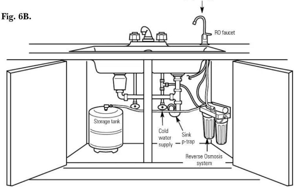
RO FAUCET—The RO product water faucet installs on the sink or on the countertop next to the sink. Often, it is installed in an existing sink spray attachment hole. Space is required underneath for tubing to and from the faucet, and for securing the faucet in place. All faucet connections and installation procedures are done on or above the sink or countertop. Refer to Fig. 1 below.
BASEMENT INSTALLATION—If installing in a basement, leave enough tubing in place during installation to be able to move unit to floor for ease at servicing and making filter/membrane changes.
*For drain line options see Filtration Drain Connection Installations section.
Step-by-step installation instructions.
Feed Water Supply
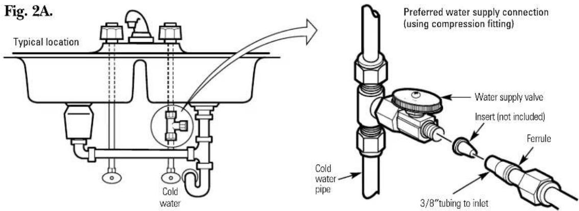
Check and comply with local plumbing codes as you plan, then install a cold feed water supply fitting. For new home installation using standard plumbing fittings, see first two illustrations below. A typical installation for existing homes using the saddle valve is shown in third illustration below.
A. PREFERRED INSTALLATION
Turn off the cold water supply.
Complying with plumbing codes, install a fitting on the cold water pipe to adapt 3/8'' OD tubing. A typical connection is shown in illustrations at right (parts not included). Make sure a water supply valve is used.
B. OPTIONAL HOME INSTALLATION Where codes permit
*For 1/2 ″OD or larger metal tubing only.
NOTE: Codes in the state of Massachusetts require installation by a licensed plumber and do not permit the use of the saddle valve. For installation, use plumbing code 248-CMR of the Commonwealth of Massachusetts.
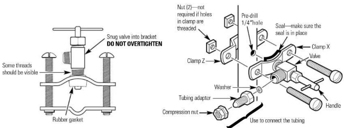
Turn off the cold water supply and attach saddle valve as shown in illustration at right.
DANGER: To protect yourself from serious injury or fatal shock, use a battery-powered hand drill only to make the hole. DO NOT USE AN ELECTRIC DRILL.
2 Close the water supply valve by turning the handle clockwise.
3 Open the main water supply valve and several house faucets to purge air from the system. Close faucets when water runs smoothly.
Fig. 2B.
*For 1/2"OD or larger metal tubing only.
Optional water supply connection (using saddle valve)*
Filtration Drain Connection Installations
Check and comply with all state and local plumbing codes as you plan.

CAUTION: The options detailed below are the ONLY approved installation configurations. Do not use any drain saddle device.
NOTE: Failure to follow these Installation Instructions will void the Warranty, and the Installer will be responsible for any service, repair or damages caused thereby.
Preferred Installation Options (Options A, B and C)
OPTION A.
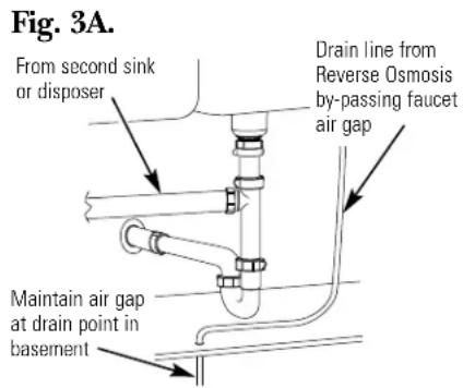
BASEMENT ACCESS INSTALLATION (Fig. 3A)
Route the drain line DIRECTLY from the Reverse Osmosis system to a standpipe in the basement, by-passing the air gap provided in the faucet. The drain line may also be routed in the basement to a floor drain or washtub, provided that the air gap in the basement is maintained. Avoid dips, loops or low spots in the drain line. The basement air gap and drain installation configuration must conform to all local codes. Special air gap fittings are available to connect the drain line to the top of the standpipe.
OPTION B.
SEPARATE VENT INSTALLATION 2 P-TRAP (DRY-VENTED) (Fig.3B)
Install a separate dry-vented p-trap under the sink to be used exclusively for the Reverse Osmosis drain line. A dry-vented p-trap is a p-trap that has its own vent/stack. Attach the provided drain line adapter to the p-trap and secure it with the slip joint nut and washer as shown. Route the drain line from the air gap to the drain line adapter ensuring that there are no dips, loops or low spots in the line, which could result in a clogged drain line. The drain line adapter should be aligned vertically such that the hose connection points in a direction 45^ off vertical. (See Fig. 3E.) The drain line must be routed through the air gap provided in the RO water faucet.

OPTION C.
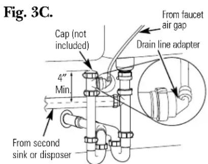
SHARED VENT INSTALLATION 2 P-TRAP (WET-VENTED) (Fig.3C)
Install a p-trap under the sink to be used exclusively for the Reverse Osmosis drain line. A wet-vented p-trap is a p-trap that shares a common vent/stack. Attach the provided drain line adapter to the p-trap and secure it with the slip joint nut and washer as shown. Route the drain line from the air gap to the drain line adapter ensuring that there are no dips, loops or low spots in the line, which could result in a clogged drain line. The drain line adapter should be aligned vertically such that the hose connection points in a direction 45^ off vertical. (See Fig. 3E.) The drain line must be routed through the air gap provided in the RO water faucet. Locate the p-trap as high as possible (minimum of 4^ above horizontal pipe from second sink or disposer).
Step-by-step installation instructions.
Filtration Drain Connection Installations
Secondary Recommendation
(Use only if option A, B or C on page 13 is not possible.)
OPTION D.
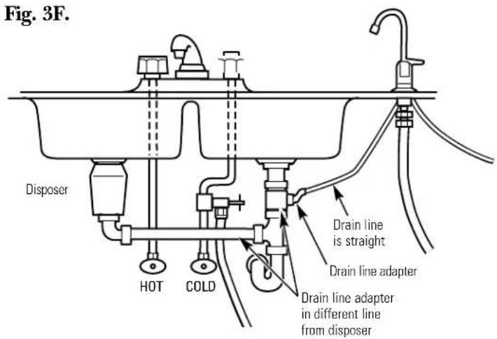
DRAIN LINE ADAPTER INSTALLATION (Fig. 3D)
DO NOT install the drain line downstream of a disposal or in a horizontal pipe. Install the provided drain line adapter under the sink as shown. The baffle-tee or y-connector shown must be in place (purchase and install if necessary) to prevent a clog in the Reverse Osmosis drain line. Route the drain line from the air gap to the drain line adapter ensuring that there are no dips, loops or low spots in the line, which could result in a clogged drain line. The drain line adapter should be aligned vertically so that the hose connection points in a direction 45^ off vertical. (See Fig. 3E.) This installation MAY result in a slight drain noise in the sink drain when the Reverse Osmosis system is operating. Rotate the Drain Line adapter tee assembly slowly until noise is minimized. Generally, 180^ opposite the existing horizontal pipe/baffle-tee is a good orientation.
CAUTION!
DO NOT INSTALL DRAIN LINE ADAPTER DOWNSTREAM FROM DISPOSER.
When installed, the tubing must not have any dips, kinks, loops, etc. The tubing must be cut to length to provide a straight routing from the faucet to the drain (Fig. 3F). See instructions in the "Filtration Drain Connection Installation" section for details and options.
INCORRECT INSTALLATION WILL RESULT IN WATER BACK-UP IN THE DRAIN LINE, WHICH WILL LEAK AT THE FAUCET!
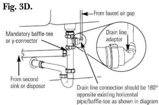
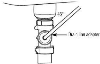
Fig. 3E.
Proper drain line adapter orientation.
Faucet Installation
Be sure there is room underneath the sink to make the needed connections. Select one of the following places to install the faucet:
IN an existing sink spray attachment or soap dispenser hole.
IN a hole to be drilled in the sink top.
IN a hole to be drilled in the countertop, next to the sink.
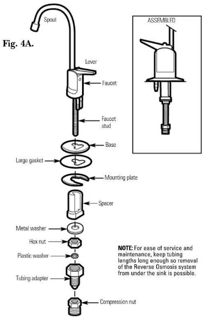
NOTE: Looking at Fig. 4B, be sure the faucet base will fit flat against the surface at the selected location so the gasket will seal.
If drilling is needed, make a 1-1/4" dia. hole. Be sure to use the proper procedure for drilling porcelain or stainless steel.
Place base on threaded stem (flange facing down). Next, place large gasket on threaded stem, making sure the stem and two barbed studs fit through the gasket. Place spacer on stud (open end up) followed by metal washer and hex nut (Fig. 4A).
3 Insert washer into tubing adapter. Securely tighten to faucet stud.
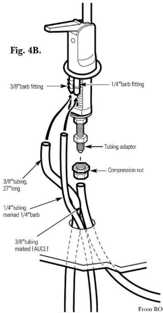
Take the 27^ length of 3 / 8'' tubing and push one end completely onto the 3 / 8'' faucet barb fitting (Fig.4B).
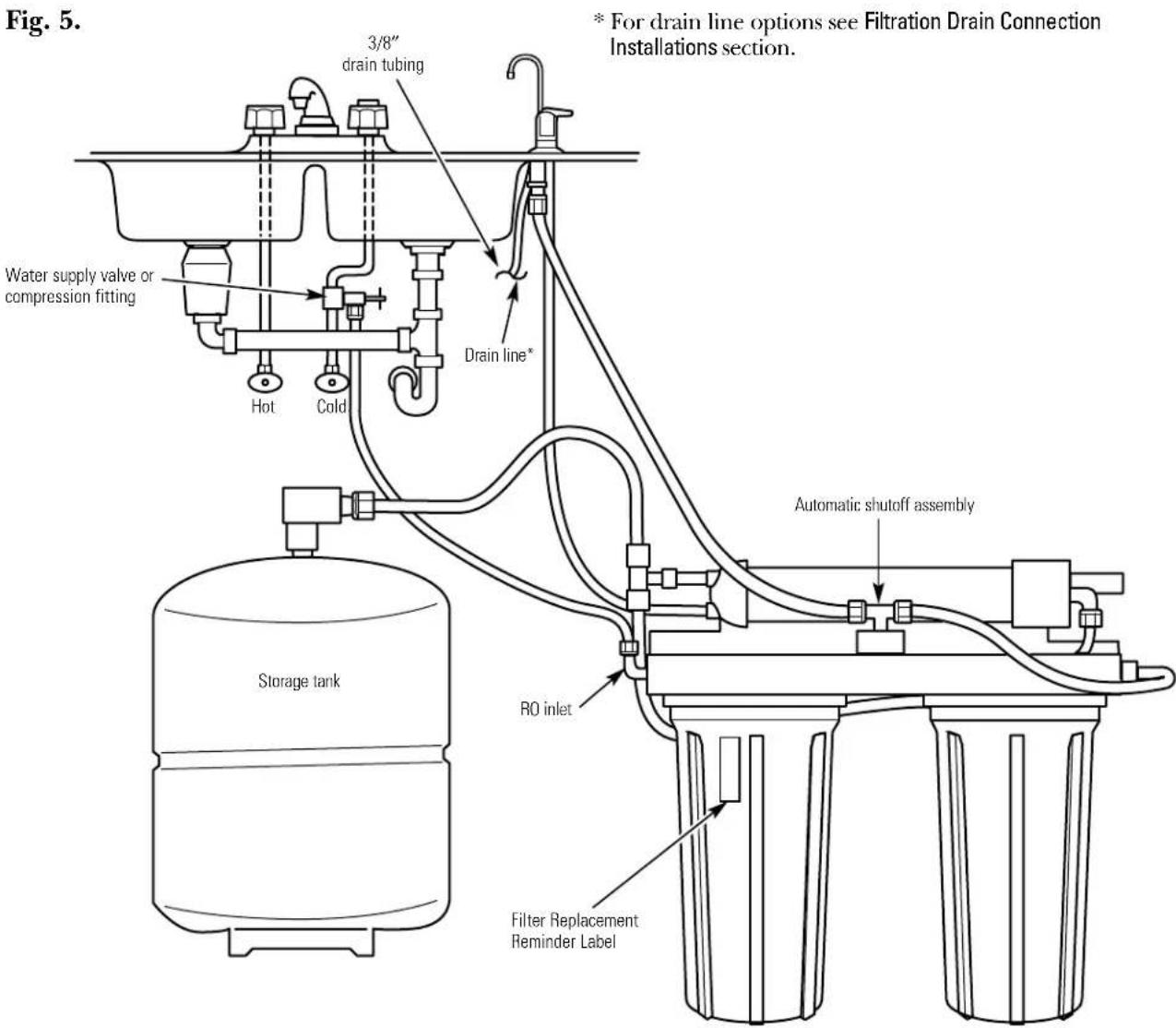
Position the Reverse Osmosis system under the sink. Referring to Fig. 5, on the next page, hang the system on cabinet wall.
6 Route the 1 / 4^ tubing (marked "1/4" BARB ON FAUCET") and the 3 / 8^ tubing (marked "FAUCET") up through the mounting hole:
Push one end of the 1 / 4'' tubing onto the 1 / 4'' barb on the faucet.
Using the compression nut, fasten the 3/8'' tubing to the tubing adapter and tighten the nut. Make sure the tubing is completely seated in the adapter.
Remove the short shipping tube and insert the spout into the faucet body.
Lower the faucet assembly through the sink.
9 Under the counter, place the mounting plate above spacer and securely tighten the hex nut.
To drain From RO
Step-by-step installation instructions.
Faucet Drain Tubing and Water Supply Tubing
If Option A, BASEMENT ACCESS INSTALLATION, scc Filtration Drain Connection Installations section, was used, go to step 2.
If Option B, C or D from page 13 or 14 was used, connect the faucet drain tubing by running the 27^ length, 3 / 8'' tubing from the 3 / 8'' faucet barb to the drain fitting (installed in Filtration Drain Connection Installations section). Keep this tubing run as short and straight as possible, without loops, dips or low-spots. Cut the tubing as needed and insert into the drain fitting (see Fig. 3B, 3C or 3D in the Filtration Drain Connection Installations section).
To connect the water supply tubing: Run the 1/4'' tubing (marked "WATER SUPPLY") from the Reverse Osmosis inlet to the feed water supply fitting (see Fig. 2A or 2B, in the Feed Water Supply section). Connect the tubing as applies (Fig. 2A or 2B, in the Feed Water Supply section) and tighten the nut securely (use Teflon Tape to prevent leaks).
Apply the Filter replacement reminder label to one of the filter sumps between the ribs. Mark the date for filter replacement six months from the installation date.
Reverse Osmosis System Assembly and Storage Tank Installation
- Hold the Reverse Osmosis assembly up to the wall surface where you will install it. Mark locations for the hanger washers and screws.
- Fasten the hanger washers to the wall surface. Wood screws are included for fastening to a wood surface. Provide other screws as needed.
- Hang the Reverse Osmosis assembly on the hanger washers.
- Connect the tubing to the storage tank: Run the length of 3/8'' tubing (marked "STORAGE TANK") from the tee fitting on the Reverse Osmosis module to the tank shutoff valve. Use Teflon Tapc™ to prevent leaks.
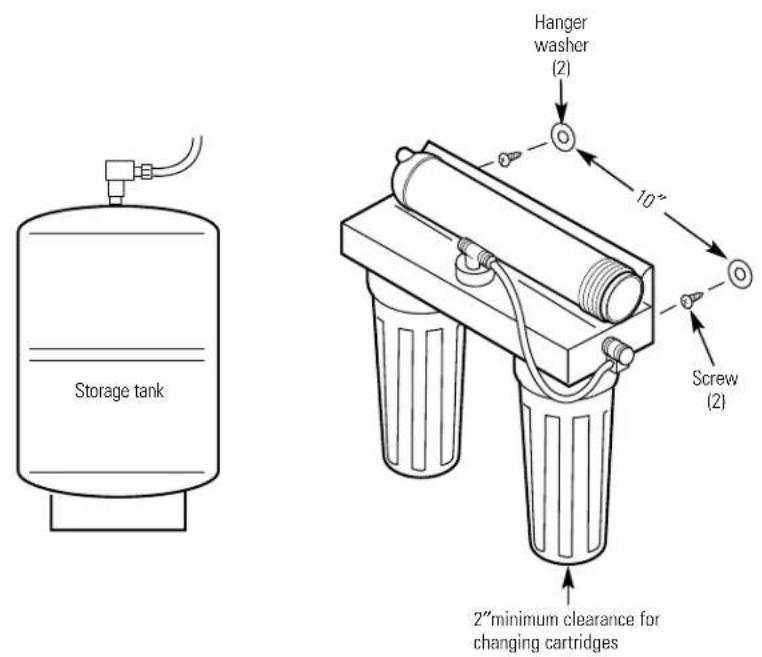
Fig. 6A.
*For drain line options see Filtration Drain Connection Installations section.
Step-by-step installation instructions.
Now That Your Reverse Osmosis System is Installed...Sanitize
Sanitize upon installation and after servicing inner parts, including replacement of prefilter, postfilter and the Reverse Osmosis cartridge. It is important to wash hands with anti-bacterial soap before handling inner parts of the system. See the Sanitizing the Reverse Osmosis System section.

CAUTION: If installing unit in New Construction, ensure house plumbing is flushed thoroughly before opening the water supply valve. Also, before sanitizing, be sure to remove all cartridges as described in the Sanitizing the Reverse Osmosis System section. Chlorine will destroy the Reverse Osmosis cartridge.
Complete Cartridge Replacement and Sanitize the System procedures (see pages 6-8), except reinstall the filters provided with the unit.
Purge membrane. See Step 12 in Reverse Osmosis Cartridge Replacement section.
3 Carefully check the system for leaks.
Installation Checklist
- Are all tubing connections tightened? Do they run between the points shown? No leaks!
- Did you use drain option B, C or D? Make sure the 3/8'' drain tubing, from the faucet to the drain point, is without loops, dips or low spots.
- Is the water supply shutoff valve open?
- Did you sanitize and purge the system?

Troubleshooting Tips
Save time and money! Review the charts on the following
pages first and you may not need to call for service.
| Problem Possible Causes What To Do | ||
| Sounds you might hear | Running water from the unit to a drain. | This is normal. |
| Water has air bubbles and is cloudy | Air in system after installation. | Will go away after water runs for a while. |
| Chlorine taste and/or The ppm of chlorine in your odor in the Reverse water supply exceeds maximum limits and has destroyed the Reverse Osmosis membrane. | If the water supply contains more than 2.0 ppm of chlorine, additional filtering of the water supply to the Reverse Osmosis is needed. Correct this condition before doing maintenance on the Reverse Osmosis system. | |
| The prefilter is no longer removing chlorine from the water supply. | Replace the Reverse Osmosis membrane cartridge, control, screen, prefilter and postfilter. | |
| Other taste and/or odor | High quality product water may have a different taste than what you're used to. | This is normal. |
| Low water usage. | Completely drain system and allow to refill. | |
| Contamination in product water storage. | Use sanitizing procedures. | |
| Prefilter and postfilter need to be changed and/or the Reverse Osmosis cartridge needs to be changed. | Replace the prefilter and postfilter. If taste and odor persists, replace the Reverse Osmosis cartridge, flow control and screen. | |
| Water leaking from faucet air gap hole | Drain side of faucet air gap (3/8" tubing) plugged, restricted or incorrectly connected to the drain point. | Inspect and eliminate restriction or plug. It is important that there are no dips, loops or low spots in the drain line from the faucet air gap to the drain pipe. Refer to the Filtration Drain Connection Installations section, for proper drain connection. If drain line adapter was used as the drain point, periodic inspection/cleaning is recommended. |
| System makes product water slowly | This is normal. | Water flow rate will be lower than your regular faucet. |
| Water supply to the Reverse Osmosis system not within specifications. | Increase water pressure, precondition the water, etc., as needed to conform before doing maintenance on the Reverse Osmosis system. | |
| Prefilter cartridge plugged with sediments and/or the Reverse Osmosis cartridge plugged with sediments. | Replace the prefilter. If rate does not increase, replace the postfilter, Reverse Osmosis cartridge, flow control and screen. | |
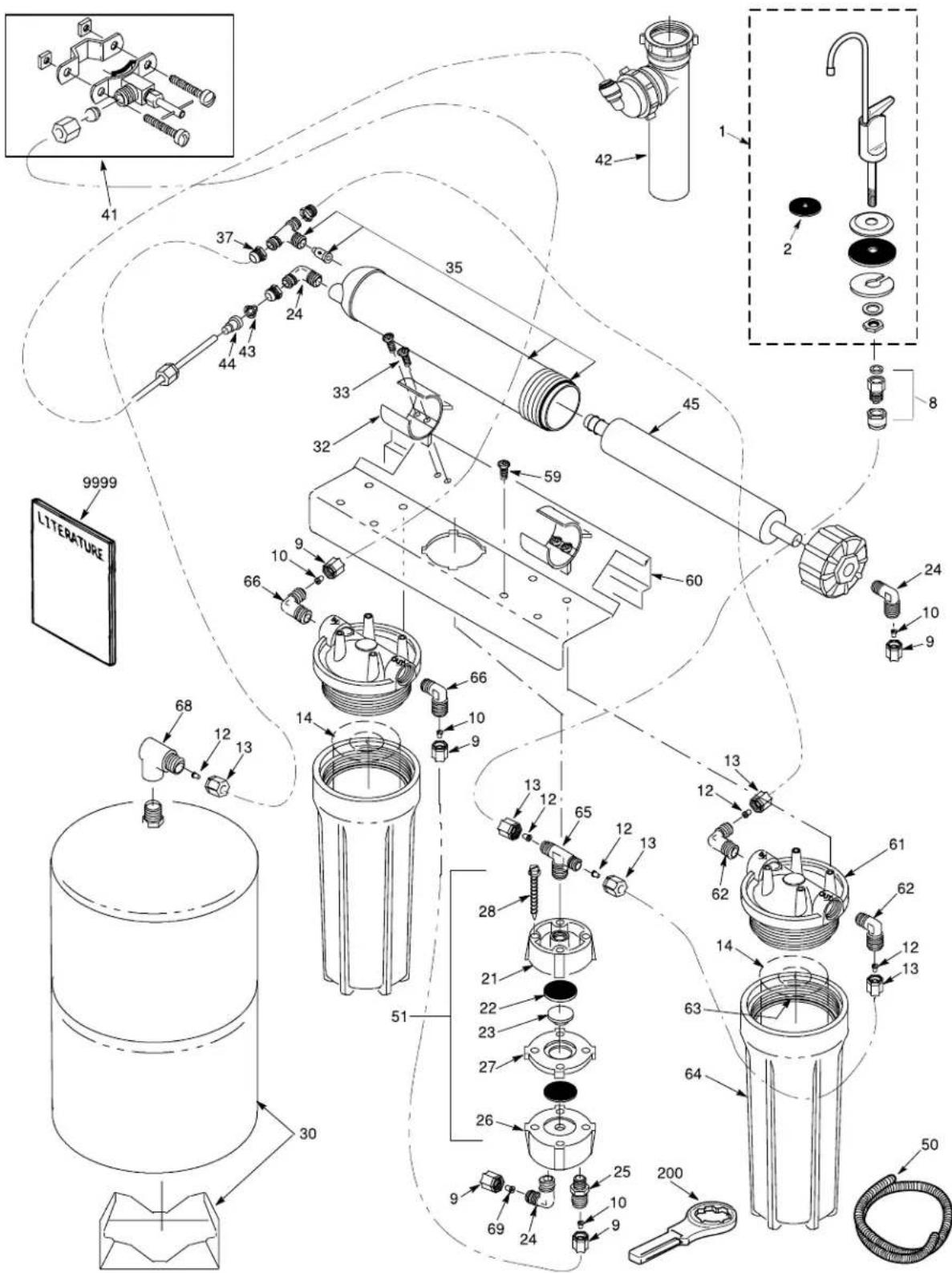
Parts list.
* NOTE: Codes in the State of Massachusetts require installation by a licensed plumber and do not permit the use of the saddle valve. For installation, use plumbing code 248-CMR of the Commonwealth of Massachusetts.
REF. NO. PART NO. PART DESCRIPTION GXRV10ABL01
| 0001 WS15X10024 FAUCET BLACK TIP & LEVER 1 | |||
| 0002 WS08X10002 GASKET TOP 1 | |||
| 0008 WS03X10003 ADAPTOR TUBING 1 | |||
| 0009 WS22X10005 | NUT 1/4" TUBE | 8 | |
| 0010 WS22X10006 | INSERT 1/4" TUBE | 7 | |
| 0012 WS22X10007 | INSERT 3/8" TUBE | 7 | |
| 0013 WS22X10008 | NUT 3/8" TUBE | 7 | |
| 0014 FX12P PRE & POST FILTERS | 2 | ||
| 0021 WS10X10005 VALVE BOTTOM | 1 | ||
| 0022 WS22X10009 DIAPHRAGM | 2 | ||
| 0023 WS22X10010 PLUNGER | 1 | ||
| 0024 WS22X10012 | ELBOW 1/8" NPT X 1/4" | 1 | |
| WS22X10011 | ELBOW 1/8" NPT X 1/4" & NUT | 3 | |
| 0025 WS22X10013 | CONNECTOR W/NUT 1/8" NPT | 1 | |
| 0026 WS10X10006 VALVE TOP | 1 | ||
| 0027 WS10X10007 VALVE CENTER | 1 | ||
| 0028 WS02X10010 | SCREW #10-14 X 1-3/4" | 4 | |
| 0030 WS32X10012 TANK 1.3 GAL. | 1 | ||
| 0032 WS02X10018 CLIP | 2 | ||
| 0033 WS02X10017 SCREW | 4 | ||
| 0035 WS35X10033 HOUSING & CHECK ASM | 1 | ||
| 0041 WS15X10023 SADDLE VALVE-SUPPLY* | 1 | ||
| 0042 WS18X10006 DRAIN LINE ADAPTER-DLA9 | 1 | ||
| 0043 WS03X10015 SCREEN CONE | 1 | ||
| 0044 WS03X10042 CONTROL FLOW | 1 | ||
| 0045 FX12M RO CARTRIDGE | 1 | ||
| 0050 WS07X10008 | TUBING 3/8" X 20 FT-WH | 1 | |
| WS07X10005 | TUBING 1/4" X 10 FT-BL | 1 | |
| WS07X10007 | TUBING 3/8" X 20 FT-BL | 1 | |
| WS07X10006 | TUBING 1/4" X 20 FT-WH | 1 | |
| 0051 WS15X10014 SHUTOFF ASSEMBLY | 1 | ||
| 0059 WS02X10020 SCREW, #10 X 1/2" | 8 | ||
| 0060 WS28X10008 BRACKET | 1 | ||
| 0061 WS19X10007 HEAD | 2 | ||
| 0062 WS22X10002 | ELBOW 3/8" NPT X 3/8" | 2 | |
| 0063 WS03X10001 | O-RING 3-3/8" X 3-5/8" | 2 | |
| 0064 WS30X10001 SUMP | 1 | ||
| 0065 WS22X10025 | TEE 1/8" NPT X 3/8" TUBE | 1 | |
| 0066 WS22X10026 | ELBOW 3/8" NPT X 1/4" TUBE | 2 | |
| 0068 WS22X10027 | ELBOW, 1/4" NPT X 3/8" | 1 | |
| 0069 WS22X10028 INSERT, FLOW CONTROL | 1 | ||
| 0200 WX5X140 WRENCH SUMP | 1 | ||
| 9999 49-50071 | OWNER'S MANUAL/INSTALLATION INSTRUCTIONS | 1 | |
To obtain replacement parts, call toll-free 800-626-2002 (U.S.), 800-663-6060 (Canada-English), 800-361-3869 (Canada-French).
- NOTE: Codes in the State of Massachusetts require installation by a licensed plumber and do not permit the use of the saddle valve. For installation, use plumbing code 248-CMR of the Commonwealth of Massachusetts.
| Consumer Support Troubleshooting Tips | Installation Instructions | Operating Instructions | Safety Instructions |
Notes.
GE Reverse Osmosis System Warranty.

All warranty service provided by our SmartWater™ Authorized Servicer Network. To schedule service on-line, 24 hours a day, contact us at www.GEApliances.com, or call toll-free 800.GE.CARES (U.S.), or 866.777.7627 (Canada).
Staple your receipt here. Proof of the original purchase date is needed to obtain service under the warranty.
For The Period Of: GE Will Replace:
One Year
From the date of the original purchase
Any part of the Reverse Osmosis Filtration System which fails due to a defect in materials or workmanship. During this limited one-year warranty, GE will also provide, free of charge, all labor (does not include service trip to home) to replace the defective part. All warranty service will be provided by a GE SmartWater™ Authorized Servicer.
What GE Will Not Cover:
■Service trips to your home to teach you how to use the product.
■Improper installation.
■Failure of the product if it is abused, misused, or used for other than the intended purpose.
■Filters or membranes.
Defects that result from improper installation or damage not caused by GE.
■Liability on the part of GE under this or any other warranty for any indirect or consequential damage.
■Products that are used for commercial or industrial applications.
■Use of this product where water is microbiologically unsafe or of unknown quality, without adequate disinfection. Systems certified for cyst reduction may be used on disinfected water that may contain filterable cysts.
■Replacement of house fuses or resetting of circuit breakers.
■Damage to the product caused by accident, fire, floods or acts of God.
■Incidental or consequential damage caused by possible defects with this appliance.
This warranty is extended to the original purchaser and any succeeding owner for products purchased for home use within the USA. In Alaska, the warranty excludes the cost of shipping or service calls to your home.
Some states do not allow the exclusion or limitation of incidental or consequential damages. This warranty gives you specific legal rights, and you may also have other rights which vary from state to state. To know what your legal rights are, consult your local or state consumer affairs office or your state's Attorney General.
THIS WARRANTY IS INTENDED TO BE IN LIEU OF ALL OTHER WARRANTYES, WHETHER EXPRESS OR IMPLIED, INCLUDING THE WARRANTYES OF MERCHANTABILITY AND FITNESS FOR A PARTICULAR PURPOSE.
Warrantor: General Electric Company. Louisville, KY 40225
Listedeverifications. 41
Instructions dinstallation.
WS22X10013 CONFECTOR CON TUERCA DE 1/8" NPT
0026 WS10X10006 PARTE SUPERIOR DE VALVULA 1
0027 WS10X10007 CENTRO DE VALVULA 1
0028 WS02X10010 TORNILLO #10-14 X 1-3/4" 4
0030 WS32X10012 TANQUE 1,3 GAL.
0032WS02X10018GRAPA 2
0033WS02X10017 TORNILLO 4
0035 WS35X10033 CAJA Y ASM DE INSPECCION 1
0041 WS15X10023 VALVULA DE MONTURA-SUMINISTRO 1
0042 WS18X10006 ADAPTADOR DE LA LINEA DE DRENAGE-DLA9
0043WS03X10015 REJILLA 1
0044WS03X10042CONTROLDEFLUTO 1
0045 FX12M CARTUCIO DEL SISTEMA DE OSMOSIS INVERSA 1
0050 WS07X10008 TUBO 3 / 8'' X20 pies-blanco 1
WS07X10005 TUBO 1 / 4'' X 10 pies-negro 1
WS07X10007 TUBO 3 / 8'' X 20 pies-negro
WS07X10006 TUBO 1 / 4^ X20 pies-blanco 1
0051 WS15X10014 MONTAJE DE APAGADO 1
0059 WS02X10020 TORNILLO #10 X 1/2" 8
0060WS28X10008RETENEDOR 1
0061WS19X10007 CABEZA 2
0062 WS22X10002 CODO 3 / 8'' NPT X 3 / 8'' 2
0063 WS03X10001 ANILLO 3-3/8" X 3-5/8" 2
0064WS30X10001SUMIDERO 1
0065 WS22X10025 TUBO EN T 1/8" NPT X 3/8" 1
0066 WS22X10026 CODO 3 / 8'' NPT X TUBO DE 1 / 4'' 2
0068 WS22X10027 CODO, 1 / 4^ NPT X 3/8" 1
0069 WS22X10028 INSERTO, CONTROL DEL FLUJO 1
0200 WX55X140 LLAVE PARA SUMIDERO 1
9999 49-50071 MANUAL DEL PROPIETARIO Y INSTALACION
| Serie | Sealed | Unsealed | Open | piped |
Garante: General Electric Company. Louisville, KY 40225
Pagina Web de GE Appliances
www.GEApliances.com
Louisville, KY 40225
Registre su electrodoméstico www.GEApliances.com
In the U.S.: www.GEApliances.com
Have a question or need assistance with your appliance? Try the GE Appliances Website 24 hours a day, any day of the year! For greater convenience and faster service, you can now download Owner's Manuals, order parts, catalogs, or even schedule service on-line. You can also "Ask Our Team of Experts" your questions, and so much more... In Canada: www.geappliances.ca
Schedule Service
In the U.S.: www.GEApliances.com
Expert GE repair service is only one step away from your door. Get on-line and schedule your service at your convenience 24 hours any day of the year! Or call 800.GE.CARES (800.432.2737) during normal business hours. In Canada, call 1.800.361.3400
Real Life Design Studio
In the U.S.: www.GEApliances.com
GE supports the Universal Design concept—products, services and environments that can be used by people of all ages, sizes and capabilities. We recognize the need to design for a wide range of physical and mental abilities and impairments. For details of GE's Universal Design applications, including kitchen design ideas for people with disabilities, check out our Website today. For the hearing impaired, please call 800.TDD.GEAC (800.833.4322).
In Canada, contact: Manager, Consumer Relations, Camco, Inc.
Suite 310, 1 Factory Lane
Moncton, N.B. E1C 9M3
Extended Warranties
In the U.S.: www.GEApliances.com
Purchase a GE extended warranty and learn about special discounts that are available while your warranty is still in effect. You can purchase it on-line anytime, or call 800.626.2224 during normal business hours. GE Consumer Home Services will still be there after your warranty expires. In Canada, call 1.888.261.2133
Parts and Accessories
In the U.S.: www.GEApliances.com
Individuals qualified to service their own appliances can have parts or accessories sent directly to their homes (VISA, MasterCard and Discover cards are accepted). Order on-line today, 24 hours every day or by phone at 800.626.2002 during normal business hours.
Instructions contained in this manual cover procedures to be performed by any user. Other servicing generally should be referred to qualified service personnel. Caution must be exercised, since improper servicing may cause unsafe operation.
Customers in Canada should consult the yellow pages for the nearest Camco service center, or call 1.888.261.3055.

Contact Us
In the U.S.: www.GEApliances.com
If you are not satisfied with the service you receive from GE, contact us on our Website with all the details including your phone number, or write to: General Manager, Customer Relations
GE Appliances, Appliance Park
Louisville, KY 40225
In Canada: www.geappliances.ca, or write to: Director, Consumer Relations, Camco, Inc.
Suite 310, 1 Factory Lane
Moncton, N.B. E1C 9M3
Register Your Appliance
In the U.S.: www.GEApliances.com
Register your new appliance on-line—at your convenience! Timely product registration will allow for enhanced communication and prompt service under the terms of your warranty, should the need arise. You may also mail in the pre-printed registration card included in the packing material, or detach and use the form in this Owner's Manual. In Canada: www.geappliances.ca

- Operating Instructions
- Care and Cleaning
- Installation Instructions
- Consumer Support
- Write the model and serial numbers here:
- Osmose Inversée
- SAFETY PRECAUTIONS
- PROPER INSTALLATION AND MAINTENANCE
- READ AND FOLLOW THIS SAFETY INFORMATION CAREFULLY.
- SAVE THESE INSTRUCTIONS
- Product - height 16" width 17" depth 6"
- About the reverse osmosis system.
- What the Reverse Osmosis System Does
- Description of the Reverse Osmosis System
- Care and cleaning of the reverse osmosis system.
- The Water Test Kit
- Prefilter and Postfilter Cartridge Replacement
- Care and cleaning—RO cartridge replacement procedure, including sanitization.
- Be sure you clean your hands with anti-bacterial soap before handling inner parts of the system.
- Reverse Osmosis Cartridge Replacement
- Installation instructions.
- Important Installation Recommendations
- Tools and Materials Required for Installation
- Things to Check Before Beginning Installation
- Step-by-step installation instructions.
- Feed Water Supply
- PREFERRED INSTALLATION
- OPTIONAL HOME INSTALLATION Where codes permit
- Filtration Drain Connection Installations
- Preferred Installation Options (Options A, B and C)
- OPTION A.
- BASEMENT ACCESS INSTALLATION (Fig. 3A)
- OPTION B.
- SEPARATE VENT INSTALLATION 2 P-TRAP (DRY-VENTED) (Fig.3B)
- OPTION C.
- SHARED VENT INSTALLATION 2 P-TRAP (WET-VENTED) (Fig.3C)
- CAUTION!
- DO NOT INSTALL DRAIN LINE ADAPTER DOWNSTREAM FROM DISPOSER.
- INCORRECT INSTALLATION WILL RESULT IN WATER BACK-UP IN THE DRAIN LINE, WHICH WILL LEAK AT THE FAUCET!
- Faucet Installation
- Faucet Drain Tubing and Water Supply Tubing
- Reverse Osmosis System Assembly and Storage Tank Installation
- Now That Your Reverse Osmosis System is Installed...Sanitize
- Installation Checklist
- Parts list.
- GE Reverse Osmosis System Warranty.
- For The Period Of: GE Will Replace:
- One Year
- What GE Will Not Cover:
- Instructions dinstallation.
- Pagina Web de GE Appliances
- www.GEApliances.com
- Registre su electrodoméstico www.GEApliances.com
- Schedule Service
- Real Life Design Studio
- Extended Warranties
- Parts and Accessories
- Contact Us
- Register Your Appliance
Brand : GE
Model : GXRV10ABL
Category : Water filter