
Profile DPVH890EJMG - Tumble drier GE - Free user manual and instructions
Find the device manual for free Profile DPVH890EJMG GE in PDF.

| Product Type | Front-loading Dryer |
| Brand | GE |
| Model | Profile DPVH890EJMG |
| Dimensions (H x W) | 100.3 cm x 68.6 cm |
| Capacity | Approximately 215 L (7.6 cu ft) |
| Power Supply | Electric 120/240 V, 60 Hz, 30 A or gas (depending on model) |
| Drying cycles | Cottons, Normal/Mixed, Wrinkle-Free, Sportswear, Delicates, Quick Dry, Steam Refresh, Steam Dewrinkle, Timed Dry, Pre-Dry, Special cycles (comforters, jeans, etc.) |
| Options | Extended Tumble, Moisture Alert, Drum Light, Delay Start, Lock, My Cycle, Dry Level (Extra Dry to Damp), Temperature (Sanitize, High, Medium, Low, Extra Low), Drying rack included |
| Technologies | Duo Dry Plus™ with Reverse Tumble™, Moisture sensors, Steam system, Demand Response (compatible optional module) |
| Lint Filter | Clean before each cycle; washable with soapy water if waxy buildup |
| Venting | Rigid or semi-rigid metal duct 4 inches (10.2 cm) to outside; rear, side, or bottom venting |
| Weight | Approximately 55 kg (121 lb) |
| Care and Cleaning | Interior and duct cleaned once a year by a professional; exterior with a damp cloth; stainless steel drum resists corrosion |
| Safety | Control lock, automatic shutdown of steam cycles, overload protection, mandatory grounding, instructions for flammable gas |
| Replacement parts | Drum light bulb, lint filter, water supply hoses, vent ducts, demand response module (optional) |
| Repairability | Repairability index not available; bulb replacement and cleaning possible by user; other repairs by a qualified technician |
| Warranty | 1 year parts and labor, 2nd year parts, 2-5 years drum and main electronic control board (depending on region) |
| General Information | Door reversal possible (30-60 min), compatibility with GE washer for cycle transfer, digital display with status messages |
Frequently Asked Questions - Profile DPVH890EJMG GE
User questions about Profile DPVH890EJMG GE
0 question about this device. Answer the ones you know or ask your own.
Ask a new question about this device
Download the instructions for your Tumble drier in PDF format for free! Find your manual Profile DPVH890EJMG - GE and take your electronic device back in hand. On this page are published all the documents necessary for the use of your device. Profile DPVH890EJMG by GE.
USER MANUAL Profile DPVH890EJMG GE
Safety Instructions 2-4
Operating Instructions
Controls 5-8
Cycle Options 9,10
Demand Response ....13
Dryer Features....10, 11
Quick Start Guide ....5
Settings Option ....10
Using the Dryer....12
Installation Instructions
Before You Begin....14, 15
Connecting the Inlet Hoses .....17
Connecting a Gas Dryer .....18-21
Connecting an
Electric Dryer .....22-24
Exhausting the Dryer .....25-31
Final Setup 32
Installing the Pedestal .....42-44
Location of your Dryer .....15, 16
Reversing the Door Swing .....33-38
Stacking the Washer
and Dryer....39-41
Troubleshooting Tips .....45-48
Consumer Support
Consumer Support ..... Back Cover
Warranty (Canada) 50
Warranty (U.S.) 49
Owner's Manual & Installation Instructions
DPVH891
DPVH890
UPVH890
Sécheuses Profile
SAVE THESE INSTRUCTIONS
Write the model and serial numbers here:
Model # ____
Serial #
They are on the label on the front of the dryer behind the door.
▲ WARNING!
For your safety, the information in this manual must be followed to minimize the risk of fire or explosion, electric shock, or to prevent property damage, personal injury, or death.
■Do not store or use gasoline or other flammable vapors and liquids in the vicinity of this or any other appliance.
■Installation and service must be performed by a qualified installer, service agency or the gas supplier.
WHAT TO DO IF YOU SMELL GAS:
1 Do not try to light a match, or cigarette, or turn on any gas or electrical appliance.
4 Immediately call your gas supplier from a neighbor's phone. Follow the gas supplier's instructions carefully.
2 Do not touch any electrical switch; do not use any phone in your building.
5 If you cannot reach your gas supplier, call the fire department.
3 Clear the room, building or area of all occupants.
California Safe Drinking Water and Toxic Enforcement Act
This act requires the governor of California to publish a list of substances known to the state to cause cancer, birth defects or other reproductive harm and requires businesses to warn customers of potential exposure to such substances.
Gas appliances can cause minor exposure to four of these substances, namely benzene, carbon monoxide, formaldehyde and soot, caused primarily by the incomplete combustion of natural gas or LP fuels.
Properly adjusted dryers will minimize incomplete combustion. Exposure to these substances can be minimized further by properly venting the dryer to the outdoors.
PROPER INSTALLATION
This dryer must be properly installed and located in accordance with the Installation Instructions before it is used. Installation Instructions are included in the back of this manual.
■Properly ground dryer to conform with all governing codes and ordinances. Follow details in Installation Instructions.
■Install or store where it will not be exposed to temperatures below freezing or exposed to water or weather.
■Connect to a properly rated, protected and sized power supply circuit to avoid electrical overload.
■Remove all sharp packing items and dispose of all shipping materials properly.
Exhaust/Ducting
1 Dryers MUST be exhausted to the outside to prevent large amounts of moisture and lint from being blown into the room.
2 Use only rigid metal 4" diameter ductwork inside the dryer cabinet. Use only rigid metal or flexible metal 4-in diameter ductwork for exhausting to the outdoors. Never use plastic or other combustible, easy-to-puncture ductwork.
For complete details, follow the Installation Instructions.
▲ WARNING!
YOUR LAUNDRY AREA
■ Keep the area underneath and around your appliances free of combustible materials, (lint, paper, rags, etc.), gasoline, chemicals and other flammable vapors and liquids.
- Keep the floor around your appliances clean and dry to reduce the possibility of slipping.
■Close supervision is necessary if this appliance is used by or near children. Do not allow children to play on, with or inside this or any other appliance.
- Keep the area around the exhaust opening and adjacent surrounding areas free from the accumulation of lint, dust and dirt.
- Keep all laundry aids (such as detergents, bleaches, etc.) out of the reach of children, preferably in a locked cabinet. Observe all warnings on container labels to avoid injury.
■Never climb on or stand on the dryer top.
WHEN USING YOUR DRYER
■ Never reach into the dryer while the drum is moving. Before loading, unloading or adding clothes, wait until the drum has completely stopped.
■Clean the lint filter before each load to prevent lint accumulation inside the dryer or in the room. DO NOT OPERATE THE DRYER WITHOUT THE LINT FILTER IN PLACE.
■Do not wash or dry articles that have been cleaned in, washed in, soaked in or spotted with combustible or explosive substances (such as wax, oil, paint, gasoline, degreasers, dry-cleaning solvents, kerosene, etc.). These substances give off vapors that may ignite or explode. Do not add these substances to the wash water. Do not use or place these substances around your washer or dryer during operation.
■Do not place items exposed to cooking oils in your dryer. Items contaminated with cooking oils may contribute to a chemical reaction that could cause a clothes load to catch fire.
■Any article on which you have used a cleaning solvent or that contains flammable materials (such as cleaning cloths, mops, towels used in beauty salons, restaurants or barber shops, etc.) must not be placed in or near the dryer until solvents or flammable materials have been removed. There are many highly flammable items used in homes such as acetone, denatured alcohol, gasoline, kerosene, some household cleaners, some spot removers, turpentine, waxes, wax removers and products containing petroleum distillates.
■The laundry process can reduce the flame retardancy of fabrics. To avoid such a result, carefully follow the garment manufacturer's care instructions.
■Do not dry articles containing rubber, plastic or similar materials such as padded bras, tennis shoes, galoshes, bath mats, rugs, bibs, baby pants, plastic bags, pillows, etc. that may melt or burn. Some rubber materials, when heated, can under certain circumstances produce fire by spontaneous combustion.
■Do not store plastic, paper or clothing that may burn or melt on top of the dryer during operation.
■ Garments labeled Dry Away from Heat or Do Not Tumble Dry (such as life jackets containing Kapok) must not be put in your dryer.
■Do not dry fiberglass articles in your dryer. Skin irritation could result from the remaining particles that may be picked up by clothing during subsequent dryer uses.
■To minimize the possibility of electric shock, unplug this appliance from the power supply or disconnect the dryer at the household distribution panel by removing the fuse or switching off the circuit breaker before attempting any maintenance or cleaning (except the removal and cleaning of the lint filter). NOTE: Pressing START/PAUSE or POWER does NOT disconnect the appliance from the power supply.
■If you see water on the floor around the dryer, call for service.
▲ WARNING!
WHEN USING YOUR DRYER (cont.)
■Never attempt to operate this appliance if it is damaged, malfunctioning, partially disassembled, or has missing or broken parts, including a damaged cord or plug.
■The interior of the machine and the exhaust duct connection inside the dryer should be cleaned at least once a year by a qualified technician. See the Sorting and Loading Hints section on page 12.
If yours is a gas dryer, it is equipped with an automatic electric ignition and does not have a pilot light. DO NOT ATTEMPT TO LIGHT WITH A MATCH. Burns may result from having your hand in the vicinity of the burner when the automatic ignition turns on.
■Do not open the dryer door during steam cycles. The steam is very hot and it will continue to exhaust from the port for several seconds after opening. Do not touch the steam port after a steam cycle.
■Do not use a steam cycle with items such as wool, leather, silk, lingerie, foam products or electric blankets.
■Do not use steam cycles on new clothes without first washing.
■You may wish to soften your laundered fabrics or reduce the static electricity in them by using a dryer-applied fabric softener or an anti-static conditioner. We recommend you use either a fabric softener in the wash cycle, according to the manufacturer's instructions for those products, or try a dryer-added product for which the manufacturer gives written assurance on the package that their product can be safely used in your dryer. Service or performance problems caused by use of these products are the responsibility of the manufacturers of those products and are not covered under the warranty of this appliance.
■Never attempt to use the Steam Dewrinkle or Steam Refresh cycles without clothes in the drum. Additionally, it is highly recommended to select the appropriate load size for best results. Selecting large load cycles for small loads may result in wetting of clothes, and selecting small load cycles for large loads may result in poor dewrinkling performance.
WHEN NOT USING YOUR DRYER
■Grasp the plug firmly when disconnecting this appliance to avoid damage to the cord while pulling. Place the cord away from traffic areas so it will not be stepped on, tripped over or subjected to damage.
■Do not attempt to repair or replace any part of this appliance or attempt any servicing unless specifically recommended in this Owner's Manual or in published user-repair instructions that you understand and have the skills to carry out.
■Before discarding a dryer, or removing it from service, remove the dryer door to prevent children from hiding inside.
■Do not tamper with controls.

READ AND FOLLOW THIS SAFETY INFORMATION CAREFULLY.
SAVE THESE INSTRUCTIONS
▲ WARNING!
To reduce the risk of fire, electric shock, or injury to persons, read the IMPORTANT SAFETY INSTRUCTIONS before operating this appliance.
Throughout this manual, features and appearance may vary from your model.
Quick Start
If the screen is dark, press the POWER button to "wake up" the display.
1 Press the POWER button.

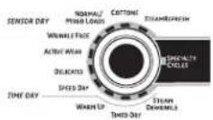
2 Select a cycle by turning the Cycle Knob.
3 If you selected a SENSOR CYCLE – just press the START/PAUSE button.

If you selected a TIMED DRY CYCLE – select your heat setting and the amount of time you want your items to dry by using the cursor buttons. Then press the START/PAUSE button.
text_image
EXTRA DRY MORE DRY DAY LESS DRY DAWP SENSOR DRY LEVEL ANTI-BACTERIAL HIGH MEDIUM LOW DRY TEMPLE EXTRA LOW START/ PAUSE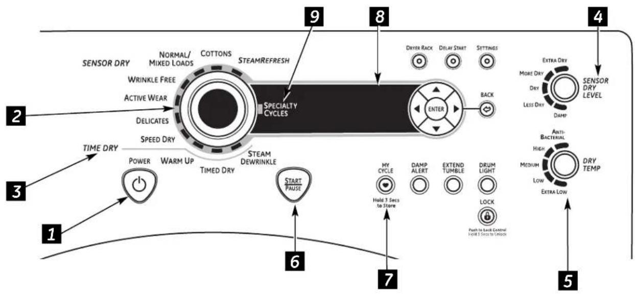
flowchart
graph TD
    A["1: TIME DRY"] --> B["2: POWER"]
    B --> C["3: TIME DRY"]
    C --> D["4: EXTRA DRY"]
    D --> E["5: ADDITIONAL"]
    E --> F["6: START PAUSE"]
    F --> G["7: HOT 3 Sets to Store"]
    G --> H["8: DELICATES"]
    H --> I["9: SPECIALTY CYCLES"]
    I --> J["10: ENTER"]
    J --> K["2: SENSOR DRY"]
    K --> L["2: NORMAL/MIXED LOADS"]
    L --> M["3: WRINKLE FREE"]
    M --> N["4: SENSOR DRY LEVEL"]
    style A fill:#f9f,stroke:#333
    style B fill:#ccf,stroke:#333
    style C fill:#cfc,stroke:#333
    style D fill:#fcc,stroke:#333
    style E fill:#cff,stroke:#333
    style F fill:#ffc,stroke:#333
    style G fill:#cfc,stroke:#333
    style H fill:#cfc,stroke:#333
    style I fill:#fcc,stroke:#333
    style J fill:#fcc,stroke:#333
    style K fill:#fcc,stroke:#333
    style L fill:#fff,stroke:#333
    style M fill:#fff,stroke:#333
    style N fill:#fff,stroke:#333
    style O fill:#fff,stroke:#333
    style P fill:#fff,stroke:#333
    style Q fill:#fff,stroke:#333
    style R fill:#fff,stroke:#333
    style S fill:#fff,stroke:#333
    style T fill:#fff,stroke:#333
    style U fill:#fff,stroke:#333
    style V fill:#fff,stroke:#333
    style W fill:#fff,stroke:#333
    style X fill:#fff,stroke:#333
    style Y fill:#fff,stroke:#333
    style Z fill:#fff,stroke:#333
1 Power
Press to "wake up" the display. If the display is active, press to turn the dryer off. NOTE: Pressing POWER does not disconnect the appliance from the power supply.
About the dryer control panel.
2 Dry Cycles
The dry cycle controls the cycle time for the drying process. The chart below will help you match the dry setting with the loads.
Sensor Cycles
| COTTONS For cottons and most linens. | |
| NORMAL/ For loads consisting of cottons and poly-blends.MIXED LOAD | |
| WRINKLE FREE For wrinkle-free/easy care and permanent press items. | |
| ACTIVE WEAR | Clothing worn for active sports exercise and some casual wear. Fabrics include new technology finishes and stretch fibers such as Spandex. |
| DELICATES For lingerie and special-care fabrics. | |
| SPEED DRY | For small loads that are needed in a hurry, such as sports or school uniforms. Can also be used if the previous cycle left some items damp, such as collars or waistbands. |
Timed Dry Cycles
| STEAM REFRESH | For slightly wrinkled dry garments. Significantly reduces wrinkles on 1-5 garments.Selecting a higher number of garments for the cycle (e.g., selecting 5-garment load for a 1-garment load) may result in excessive wetting of clothes. After the SteamRefresh Cycle, the unit will beep and display “Garments Ready” and “0:00.” If the unit is not turned off or if the door is not opened, the dryer will continue to tumble for 30 minutes. At the end of 30 minutes, it will display “0:00” and “Cycle Complete.”A single extremely light fabric item may need to have an additional item included in the steam refresh cycle to achieve optimum results. |
| STEAM DEWRINKLE | For use with larger loads than STEAM REFRESH. Ideal for loads left in dryer for an extended time. Selecting a larger cycle than needed (e.g., selecting Large Load for a half-full dryer) may result in excessive wetting of clothes. |
WARM UP Provides 10 minutes of warming time to warm up clothes.
My Cycle (on some models)
MY CYCLE Press to use, create or modify custom dry cycles.
3 Timed Dry
Use to set your own dry time. TIMED DRY is also recommended for small loads.
To use TIMED DRY:
- Turn dry cycle dial to TIMED DRY.
- Select the drying time by pressing the ▲ and ▼ buttons. You can increase the time in 10-minute increments up to 2½ hours.
- Select the DRY TEMP.
- Close the door.
- Press START/PAUSE.
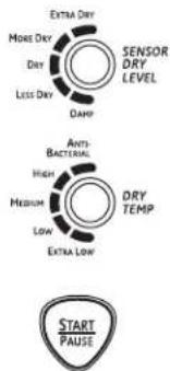
4 Sensor Dry Level
The sensor continuously monitors the amount of moisture in the load. When the moisture in your clothes reaches your selected dry level, the dryer will stop.
EXTRA DRY Use for heavy-duty fabrics or items that should be very dry, such as towels.
MORE DRY Use for heavy or mixed type of fabrics.
DRY Use for normal dryness level suitable for most loads. This is the preferred cycle for energy saving.
LESS DRY Use for lighter fabric (ideal for ironing).
DAMP For leaving items partially damp.
5 Dry Temp
You can change the temperature of your dry cycle.
ANTI-BACTERIAL
This option may only be used with COTTONS or MIXED LOAD cycles. This option reduces certain types of bacteria by 99.9%, including: Staphylococcus aureus, Pseudomonas aeruginosa and Klebsiella pneumoniae*. The anti-bacterial process occurs when high heat is used during a portion of this drying cycle.
NOTE: Do not use this cycle on delicate fabrics.
* The Anti-Bacterial Cycle is Certified by NSF International (formerly National Sanitation Foundation) to NSF Protocol P154 Sanitization Performance of Residential Clothes Dryers.

NSF Protocol P154 Sanitization Performance of Residential Clothes Dryers
HIGH For regular to heavy cottons.
MEDIUM For synthetics, blends and items labeled permanent press.
LOW For delicates, synthetics and items labeled Tumble Dry Low.
EXTRA LOW For lingerie and special-care fabrics.
START/PAUSE
Press to start a dry cycle. If the dryer is running, press it once and it will pause the dryer. Press it again to restart the dry cycle.
7 MY CYCLE My Cycle (on some models)

Set up your favorite combination of settings and save them here for one touch recall. These custom settings can be set while a cycle is in progress.
To store a MY CYCLE combination of settings:
- Select your drying cycle.
- Change DRY TEMP and SENSOR DRY LEVEL settings to fit your needs.
- Select any drying OPTIONS you want.
- Press and hold the MY CYCLE button for 3 seconds to store your selection. A beep will sound and the button will light up.
To recall your stored MY CYCLE combination:
Press the MY CYCLE button before drying a load. The light around the button will light up when MY CYCLE is selected.
To change your stored MY CYCLE combination:
Follow Steps 1-4 in "To store a MY CYCLE combination of settings."
8 Display
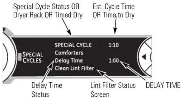
text_image
Special Cycle Status OR Dryer Rack OR Timed Dry Est. Cycle Time OR Time to Dry SPECIAL CYCLE COMFORTERS 1:10 SPECIAL CYCLE Delay Time Clean Lint Filter 1:00 Delay Time Status Lint Filter Status Screen DELAY TIME"CLEAN LINT FILTER" (message)
This message stays on for 15 minutes after the cycle finishes. This message is only a reminder.
About the dryer control panel.
9 Specialty Cycles
- Turn the CYCLE knob to SPECIAL CYCLES. A list of cycle options will appear in the display.
- Using the cursor buttons, select a CATEGORY.
- Using the cursor buttons, select a CYCLE.
Press the BACK button to take you back to the CATEGORIES. - Press ENTER to select.
- Press the START/PAUSE button.
SPECIALTY CYCLES include:
Garments
Coats
■Hosiery/Bras (use mesh bag)
Jeans
Khakis
Bed and Bath
■Blankets (Cotton)
■Comforters
Sheets
Towels
Other Specialty
Air Fluff
Dryel
■Fleece
■Fragile Cotton
■Performance Fabrics
■Pet Bedding
■Play Clothes
■Sleeping Bags
Rack Dry
■Throw Rugs
Washer Communicated Cycles
To turn on communication, press the SETTINGS button on the washer control panel. When "DRYER LINK" appears in the display, press ENTER. Using the arrow keys, select ON; then press ENTER.
When the washer cycle is completed, the washer will communicate with the dryer when any button on the control panel is touched or the door is opened.
The washer will display, "TRANSFERRING CYCLE INFORMATION TO THE DRYER" and the dryer will display, "RECEIVING CYCLE INFORMATION TO THE DRYER".
The dryer will only communicate with the washer if the dryer is not running a cycle.
If the washer starts a new cycle before the dryer has a chance to communicate with it, the information will be lost.
About cycle options.
NOTE: Not all features are available on all dryer models.
GEAppliances.com
 | Extend TumbleMinimizes wrinkles by adding approximately 60 minutes of no-heat tumbling after clothes are dry.The light around the button will light up when EXTEND TUMBLE is on. | Extend Tumble is automatically selected for the SteamRefresh cycle and cannot be deselected. Dryer will beep and display "Garments Ready" when SteamRefresh is complete. The dryer will continue in Extend Tumble until the door is opened. |
 | ||
 | Damp AlertThis option causes the dryer to beep when clothes have dried to a damp level. Remove items that you wish to hang dry. The DAMP ALERT will only beep when this option is selected. | Removing clothes and hanging them when they are damp can reduce the need to iron some items.The light around the button will light up when DAMP ALERT is on. |
 | ||
 | Drum LightPress this button to turn on the light in the dryer. | The light around the button will light up when DRUM LIGHT is on. |
 | Press the button again to turn the light off.This only controls the light when the door is shut. NOTE: The light will turn off by itself after one minute when the door is shut.When the door is opened, the light comes on automatically. | |
 | Delay StartUse to delay the start of your dryer.1. Choose your dry cycle and any options.2. Press DELAY START. You can change the delay time in 1/2-hour increments, using the ▲or ▼arrow pads.3. Press the START/PAUSE button to start the countdown.The countdown time will be shown in the ESTIMATED TIME REMAINING display. | NOTES:■If the door is opened while the dryer is in DELAY, the countdown time will not restart unless the door is closed and START/PAUSE button has been pressed again.■You can delay the start of a dry cycle up to 24 hours.The light around the button will light up when DELAY START is on. |
 | ||
 | LockYou can lock the controls to prevent any selections from being made. Or you can lock the controls after you have started a cycle.Children cannot accidentally start the dryer by touching pads with this option selected. | To lock the dryer, press the LOCK button.To unlock the dryer, press and hold the LOCK button for 3 seconds.The light around the LOCK button will light up when the controls are locked.Even though the controls are locked, the POWER button is still active in case you have |
| Press to lock control.Hold 3 seconds to unlock. |
About cycle options.
NOTE: Not all features are available on all dryer models.
SETTINGS
Settings
Under the SETTINGS option, you can adjust the volume or the brightness of the display.
VOLUME
■End of Cycle (signal) volume can be set from HIGH, MED, LOW or OFF.
■Control Sounds volume can be set from HIGH, MED, LOW or OFF.
DISPLAY BRIGHTNESS can be set from HIGH, MED or LOW.
After you have made your selection, press ENTER.
About dryer features.
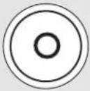
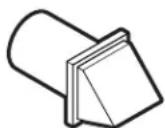
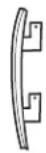
natural_image
Pure technical line drawing of a mechanical component or bracket (no text or symbols)Drum Lamp
Before replacing the light bulb, be sure to unplug the dryer power cord or disconnect the dryer at the household distribution panel by removing the fuse or switching off the circuit breaker. Reach above dryer opening from inside the drum. Remove the bulb and replace with the same size bulb.
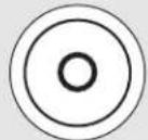
natural_image
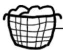
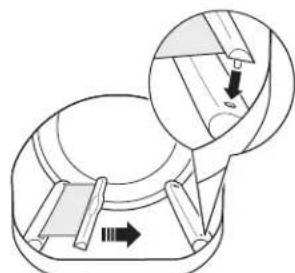
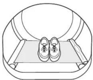
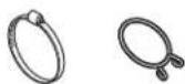
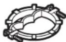
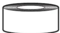
Simple line drawing of a circular object with two side protrusions, resembling a mechanical or architectural component (no text or symbols)Built-In Rack Dry System
A handy drying rack may be used for drying items such as tennis shoes. Place items flat on the drying rack and block such items as wool sweaters and delicate fabrics. Dry with low heat.
To install the Built-In Rack Dry System
- Make sure the drum of the dryer is oriented so the rack drying system is on the left side of the dryer.
- Pull the drying rack screen out from the left side and engage the handle "posts" in the opposite baffle slots.
- Place the garment on the rack and close the door.
- Press the DRYER RACK button.
- Select desired TIME.
- Press the START/PAUSE button.
NOTE:
■Do not use this drying rack when there are other clothes in the dryer.
■Make sure to detach the drying rack at the end of the cycle and fully retract the screen back into the baffle.
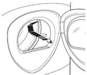
natural_image
Diagram of a mechanical component with an inset showing a close-up view of a cylindrical part (no text or symbols present)Engage the handle posts
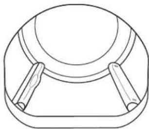
natural_image
Line drawing of a person's feet resting on a tray with a circular frame (no text or symbols)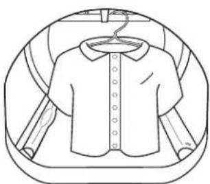
natural_image
Line drawing of a short-sleeve shirt with collar, enclosed in a circular frame (no text or symbols)To Use the Built-In Hook for Hanging Garments
- Make sure the drum of the dryer is oriented so the hook is on the top center of the dryer.
- Using your finger, pull the hook out of the baffle.
- Hang the garment on a hanger, hang the hanger on the hook and close the door.
- Press the DRYER RACK button.
- Select the desired time.
- Press the START/PAUSE button.
Reverse Tumble™
All Profile front-load matching dryers are equipped with the Reverse Tumble™ feature, as part of the Duo Dry Plus system™. By reversing the direction of drum rotation during the drying cycle, your dryer will tangle the clothes load less, dry more evenly and improve drying times. Typical loads such as bed and bath mixed loads, where sheets, towels and pillow cases are laundered together, benefit from this capability. When the dryer reverses direction, there will be a slight pause and sound change. This is normal. All dryer cycles utilize this feature, except when the rack dry option is selected, in which case the drum does not tumble.
Using the dryer.
Always follow fabric manufacturer's care label when laundering.
Sorting and Loading Hints
As a general rule, if clothes are sorted properly for the washer, they are sorted properly for the dryer. Try also to sort items according to size. For example, do not dry a sheet with socks or other small items.
Do not add fabric softener sheets once the load has become warm. They may cause fabric softener stains. Bounce® Fabric Conditioner Dryer Sheets have
been approved for use in this dryer when used in accordance with the manufacturer's instructions.
See below for lint filter cleaning instructions.
Do not overload. This wastes energy and causes wrinkling.
Do not dry the following items: fiberglass items, woolens, rubber-coated items, plastics, items with plastic trim and foam-filled items.
Fabric Care Labels
Below are fabric care label "symbols" that affect the clothing you will be laundering.
Dry Labels
Tumble dry

Dry

Normal

Permanent Press/wrinkle resistant

Gentle/ delicate

Do not tumble dry

Do not dry (used with do not wash)
Heat setting

High

Medium

Low

No heat/air
Special instructions

Line dry/ hang to dry

Drip dry

Dry flat

In the shade
natural_image
Diagram of a mechanical component with a central component and surrounding parts (no text or symbols)Care and Cleaning of the Dryer
Dryer Interior and Duct: The interior of the appliance and exhaust duct should be cleaned once a year by qualified service personnel.
The Exterior: Wipe or dust any spills or washing compounds with a damp cloth. Dryer control panel and finishes may be damaged by some laundry pretreatment soil and stain remover products. Apply these products away from the dryer. The fabric may then be washed and dried normally. Damage to your dryer caused by these products is not covered by your warranty.
Do not touch the surface or the display with sharp objects.
The Lint Filter: Clean the lint filter before each use. Remove by pulling straight up. Run your fingers across the filter. A waxy buildup may form on the lint filter from using dryer-added fabric softener sheets. To remove this buildup, wash the lint screen in warm, soapy water. Dry
thoroughly and replace. Do not operate the dryer without the lint filter in place.
Vacuum the lint from the dryer lint filter if you notice a change in dryer performance.
Stainless Steel: To clean stainless steel surfaces, use a damp cloth with a mild, nonabrasive cleaner suitable for stainless steel surfaces. Remove the cleaner residue, and then dry with a clean cloth. The stainless steel used to make the dryer drum provides the highest reliability available in a GE dryer. If the dryer drum should be scratched or dented during normal use, the drum will not rust or corrode. These surface blemishes will not affect the function or durability of the drum.
The Exhaust Hood: Check with a mirror that the inside flaps of the hood move freely when operating. Make sure that there is no wildlife (birds, insects, etc.) nesting inside the duct or hood.
Model DPVH891 is compatible with the GE Demand Response (DR) module which can be purchased separately. Contact your local utility or visit www.GEAppliances.com/demand_response to see if your area is using DR technology.
The following demand response features are available as part of a pilot test program with the local utility company to help consumers reduce peak electricity usage in the home.
Installation
The preferred location for the module installation is on top of the clothes dryer.
Details on how to connect the cables to the module are in the instructions that come with the module.
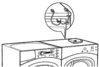
natural_image
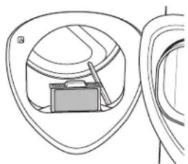
Line drawing of a washing machine with a magnified inset showing internal components (no text or symbols)Wait 5 minutes; then press the Settings button. Scroll and look for the energy management screen as seen below.

This screen means the module is attached correctly and you can begin to use your DR-enabled appliance following the instructions below.
If the Energy Management Screen is not available, refer to the DR module troubleshooting guide.
Quick Guide
There are 4 power levels available: Critical, High, Medium and Low. On the Medium and Low levels, the unit runs as normal. The following steps show how the unit reacts during startup at Critical and High power levels.
Option 1 (Delay Eco)
During startups at Critical and High levels, the unit will delay starting until the level becomes Medium or Low. Press the START/PAUSE button.

Option 2 (Override Delay Eco)
To start the unit when Delay Eco is shown, press the DELAY START button to turn the delay off. Then press START/PAUSE to begin the cycle.
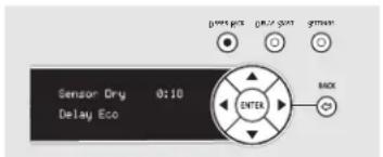
text_image
Sensor Dry 0:10 Delay Eco ENTER BACKSettings Menu
Press SETTINGS; then select Energy Management.

text_image
ENERGY MANAGEMENT Delay Eco Override Auto-Extend Delays Timed Dry Eco OptionDelay Eco Override
If you are starting a cycle in a Critical or High utility rate, this option allows the unit to automatically run on an Eco Cycle. This setting will operate with less energy than normal cycles. Default setting is YES.

text_image
Run in Eco Mode when starting cycles in High utility rate? YES NOAuto-Extend Delays
If a timed delay is selected, this option allows for the scheduled start to extend if the utility rate is Critical or High at the scheduled start. The default setting will automatically extend these cycles.

text_image
Extend delay time if utility rate is high at scheduled start? YES NOTimed Dry Eco Option
If the unit is running in Timed Dry Mode and the utility rate switches to Critical or High, the unit will conserve energy by decreasing heat if YES (default) is selected. If NO is selected, the unit will operate normally.
NOTE: When YES (default) is selected, your load may be damp at the end of the cycle.

text_image
Switch to Eco Mode if utility rate goes high during cycle? YES NOIn order for the demand response features on the appliance to work, additional equipment is required to be installed to interface with the local utility. Such equipment may be sold separately and/or is available through your utility as part of the pilot test program. Check with your utility company to see if a pilot test program is available in your area and for full details.
PLEASE NOTE: At the conclusion of the pilot test program or if you move to an area where the program is not available, the demand response features cannot be activated and utilized on the appliance. The appliance will function as normal after the demand response equipment has been deactivated or disconnected.
Installation Instructions
Dryer
DPVH891, DPVH890, UPVH890
Questions? Call 800.GE.CARES (800.432.2737) or visit our Web site at: GEAppliances.com
In Canada, call 1.800.561.3344 or visit www.GEAppliances.ca
BEFORE YOU BEGIN
Read these instructions completely and carefully.
- IMPORTANT – Save these instructions for local electrical inspector's use.
- IMPORTANT – Observe all governing codes and ordinances.
- Install the clothes dryer according to the manufacturer's instructions and local codes.
- Note to Installer – Be sure to leave these instructions with the Consumer.
- Note to Consumer – Keep these instructions for future reference.
- Clothes dryer installation must be performed by a qualified installer.
- This dryer must be exhausted to the outdoors.
- Before the old dryer is removed from service or discarded, remove the dryer door.
- Service information and the wiring diagram are located in the control console.
- Do not allow children on or in the appliance. Close supervision of children is necessary when the appliance is used near children.
- Proper installation is the responsibility of the installer.
- Product failure due to improper installation is not covered under the Warranty.
• Install the dryer where the temperature is above 50^ F for satisfactory operation of the dryer control system. - Remove and discard existing plastic or metal foil duct and replace with UL-listed duct.
CALIFORNIA SAFE DRINKING WATER AND TOXIC ENFORCEMENT ACT
This act requires the governor of California to publish a list of substances known to the state to cause cancer, birth defects or other reproductive harm and requires businesses to warn customers of potential exposure to such substances. Gas appliances can cause minor exposure to four of these substances, namely benzene, carbon monoxide, formaldehyde and soot, caused primarily by the incomplete combustion of natural gas or LP fuels. Properly adjusted dryers will minimize incomplete combustion. Exposure to these substances can be minimized further by properly venting the dryer to the outdoors.
FOR YOUR SAFETY:
⚠ WARNING – Risk of Fire
- To reduce the risk of severe injury or death, follow all installation instructions.
- Clothes dryer installation must be performed by a qualified installer.
• Install the clothes dryer according to these instructions and in accordance with local codes. - This dryer must be exhausted to the outdoors.
- Use only 4" rigid metal ducting for exhausting the clothes dryer to the outdoors.
- DO NOT install a clothes dryer with flexible plastic ducting materials. If flexible metal (semi-rigid or foil-type) duct is installed, it must be UL-listed and installed in accordance with the instructions found in "Connecting the Dryer to House Vent" on page 26 of this manual. Flexible ducting materials are known to collapse, be easily crushed and trap lint. These conditions will obstruct dryer airflow and increase the risk of fire.
- Do not install or store this appliance in any location where it could be exposed to water and/or weather.
- Save these instructions. (Installers: Be sure to leave these instructions with the customer.)
NOTE: Installation and service of this dryer must be performed by a qualified installer, service agency or the gas supplier.
In the Commonwealth of Massachusetts:
- This product must be installed by a licensed plumber or gas fitter.
- When using ball-type gas shut-off valves, they shall be T-handle-type.
- A flexible gas connector, when used, must not exceed 3 feet.
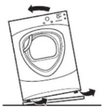
UNPACKING YOUR DRYER
Tilt the dryer sideways and remove the foam shipping pads by pulling at the sides and breaking them away from the dryer legs. Be sure to remove all of the foam pieces around the legs.
Remove the bag containing the literature and serial cable.
natural_image
Line drawing of a washing machine with airflow arrows indicating direction (no text or symbols)Minimum clearance to combustible surfaces and for air openings are:
- 0 inch clearance both sides
- 1 inch front
- 3 inches rear
Consideration must be given to provide adequate clearance for proper operation and service.
DRYER DIMENSIONS
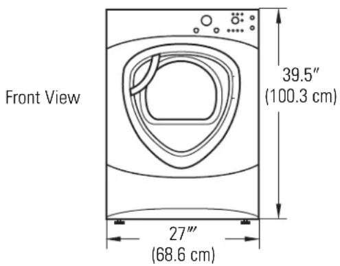
text_image
Front View 39.5" (100.3 cm) 27" (68.6 cm)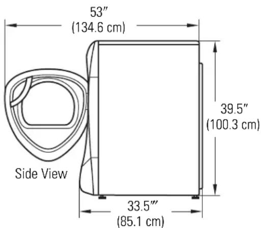
text_image
53" (134.6 cm) 39.5" (100.3 cm) 33.5" (85.1 cm) Side ViewREQUIREMENTS FOR ALCOVE OR CLOSET INSTALLATION
- Your dryer is approved for installation in an alcove or closet, as stated on a label on the dryer back.
- The dryer MUST be vented to the outdoors. See the EXHAUSTING THE DRYER section.
- Minimum clearance between dryer cabinet and adjacent walls or other surfaces is:
0" either side
3" front and rear
- Minimum vertical space from floor to overhead shelves, cabinets, ceilings, etc., is 52".
- Closet doors must be louvered or otherwise ventilated and have at least 60 square inches of open area equally distributed. If the closet contains both a washer and a dryer, doors must contain a minimum of 120 square inches of open area equally distributed.
- The closet should be vented to the outdoors to prevent gas pocketing in case of gas in the supply line.
- No other fuel-burning appliance shall be installed in the same closet with the dryer (gas models only).
NOTE: WHEN THE EXHAUST DUCT IS LOCATED AT THE REAR OF THE DRYER, MINIMUM CLEARANCE FROM THE WALL IS 5.5 INCHES.
BATHROOM OR BEDROOM INSTALLATION
- The dryer MUST be vented to the outdoors. See EXHAUSTING THE DRYER.
- The installation must conform with local codes or, in the absence of local codes, with the NATIONAL ELECTRICAL CODE, ANSI/NFPA NO. 70 (for electric dryers) or NATIONAL FUEL GAS CODE, ANSI Z223 (for gas dryers).
MOBILE OR MANUFACTURED HOME INSTALLATION
- The installation must conform to the MANUFACTURED HOME CONSTRUCTION & SAFETY STANDARD, TITLE 24, PART 32-80 or, when such standard is not applicable, with AMERICAN NATIONAL STANDARD FOR MOBILE HOME, NO. 501B.
- The dryer MUST be vented to the outdoors with the termination securely fastened to the mobile home structure. (See EXHAUSTING THE DRYER.)
- The vent MUST NOT be terminated beneath a mobile or manufactured home.
- The vent duct material MUST BE METAL.
- FOR GAS MODELS ONLY: KIT 14-D346-33 MUST be used to attach the dryer securely to the structure.
- FOR GAS MODELS ONLY: The vent MUST NOT be connected to any other duct, vent or chimney.
- Do not use sheet metal screws or other refastening devices which extend into the interior of the exhaust vent.
- Provide an opening with a free area of at least 25 sq. in. for introduction of outside air into the dryer room.
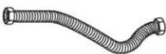
CONNECTING INLET HOSES
CONNECTING INLET HOSES
To produce steam, the dryer must connect to the cold water supply. Since the washer must also connect to the cold water, a "Y" connector is inserted to allow both inlet hoses to make that connection at the same time.
NOTE: Use the new inlet hoses provided; never use old hoses.
- Turn the cold water faucet off. Remove the washer inlet hose from the washer fill valve connector (cold).
- Ensure the rubber flat washer is in place and screw the female coupling of the short hose onto the washer fill valve connector. Tighten by hand until firmly seated.
- Attach the female end of the "Y" connector to the male coupling of the short hose. Ensure the rubber flat washer is in place. Tighten by hand until firmly seated.
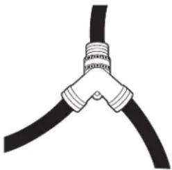
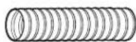
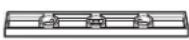
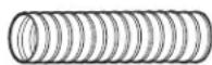
natural_image
Illustration of two black cables with coiled cable ties (no text or symbols)- Insert the filter screen in the coupling of the washer's inlet hose. If a rubber flat washer is already in place remove it before installing the filter screen. Attach this coupling to one male end of the "Y" connector. Tighten by hand until firmly seated.
- Ensure the rubber flat washer is in place and attach the dryer's long inlet hose to the other male end of the "Y" connector. Tighten by hand until firmly seated.
- Ensure the rubber flat washer is in place and attach the other end of the dryer's long inlet hose to the fill valve connector at the bottom of the dryer back panel. Tighten by hand until firmly seated.
CONNECTING INLET HOSES (cont.)
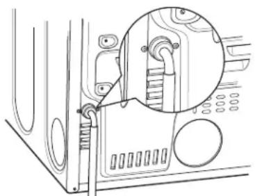
natural_image
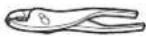
Technical line drawing of a mechanical component with an inset close-up view (no text or symbols)- Using pliers, tighten all the couplings with an additional two-thirds turn.
NOTE: Do not overtighten. Damage to the couplings may result.
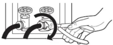
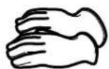
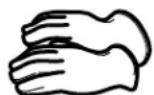
natural_image
Illustration of hands connecting pipe fittings to a valve (no text or symbols)- Turn the water faucet on.
- Check for leaks around the "Y" connector, faucet and hose couplings.
WATER SUPPLY REQUIREMENTS
Hot and cold water faucets MUST be installed within 42 in. (107 cm) of your washer's water inlet. The faucets MUST be 3/4 in. (1.9 cm) garden hose-type so inlet hoses can be connected. Water pressure MUST be between 10 and 120 pounds per square inch. Your water department can advise you of your water pressure.
NOTE: A water softener is recommended to reduce buildup of scale inside the steam generator if the home water supply is very hard.
CONNECTING A GAS DRYER (skip for electric dryers)
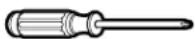
TOOLS YOU WILL NEED
☐ 10" Adjustable wrenches (2)
Flat-blade screwdriver
☐8" Pipe wrench
Level
□Slip-joint pliers
MATERIALS YOU WILL NEED

☐ 4" dia. metal elbow
☐4" dia., UL-listed flexible metal duct (if needed)
□Pipe compound
Gloves
☐Flexible gas line connector

□Soap solution for leak detection
☐Duct clamps (2) or Spring clamps (2)
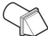
Exhaust hood
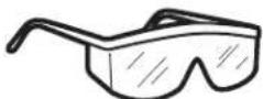
□Safety glasses
□Duct tape

☐ 4" dia. metal duct (recommended)
FOR YOUR SAFETY:
WARNING
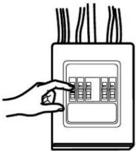
Before beginning the installation, turn off the circuit breaker(s) or remove the dryer's circuit fuse(s) at the electrical box. Be sure the dryer cord is unplugged from the wall.
natural_image
Hand placing a button into an electrical outlet panel (no text or symbols visible)Turn the dryer's gas shut-off valve in the supply line to the OFF position.
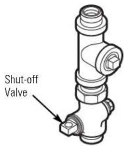
text_image
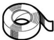
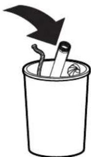
Shut-off ValveDisconnect and discard old flexible gas connector and ducting material.
natural_image
Simple line drawing of a trash bin with a downward arrow and scattered trash (no text or symbols)GAS REQUIREMENTS
WARNING
• Installation must conform to local codes and ordinances, or in their absence, the NATIONAL FUEL GAS CODE, ANSI Z223.
- This gas dryer is equipped with a Valve and Burner Assembly for use only with natural gas. Using conversion kit 14-A048, your local service organization can convert this dryer for use with propane (LP) gas. ALL CONVERSIONS MUST BE MADE BY PROPERLY TRAINED AND QUALIFIED PERSONNEL AND IN ACCORDANCE WITH LOCAL CODES AND ORDINANCE REQUIREMENTS.
- The dryer must be disconnected from the gas supply piping system during any pressure testing of that system at a test pressure in excess of 0.5 PSI (3.4 KPa).
- The dryer must be isolated from the gas supply piping system by closing the equipment shut-off valve during any pressure testing of the gas supply piping of test pressure equal to or less than 0.5 PSI (3.4KPa).
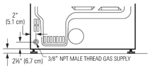
DRYER GAS SUPPLY CONNECTION
text_image
2" (5.1 cm) 2½" (6.7 cm) 3/8" NPT MALE THREAD GAS SUPPLYNOTE: Add to vertical dimension the distance between cabinet bottom to floor.
GAS SUPPLY
- A 1/8" National Pipe Taper thread plugged tapping, accessible for test gauge connection, must be installed immediately upstream of the gas supply connection to the dryer. Contact your local gas utility should you have questions on the installation of the plugged tapping.
- Supply line is to be 1/2" rigid pipe and equipped with an accessible shutoff within 6 feet of, and in the same room with, the dryer.
- Use pipe thread compound appropriate for natural or LP gas or use Teflon® tape.
- Connect flexible metal connector to dryer and gas supply.
IN THE COMMONWEALTH OF MASSACHUSETTS
- This product must be installed by a licensed plumber or gas fitter.
- When using ball-type gas shut-off valves, they shall be the T-handle type.
- A flexible gas connector, when used, must not exceed 3 feet.
ADJUSTING FOR ELEVATION
- Gas clothes dryers input ratings are based on sea level operation and need not be adjusted for operation at or below 2000 ft. elevation. For operation at elevations above 2000 ft., input ratings should be reduced at a rate of 4 percent for each 1000 ft. above sea level.
- Installation must conform to local codes and ordinances or, in their absence, the NATIONAL FUEL GAS CODE, ANSI Z223.
CONNECTING A GAS DRYER (cont.)
CONNECTING THE DRYER TO THE GAS SUPPLY
A Install a female 3/8" NPT elbow at the end of the dryer gas inlet. Install a 3/8" flare union adapter to the female elbow.
IMPORTANT: Use a pipe wrench to securely hold on to the end of the dryer gas inlet to prevent twisting the inlet.
NOTE: Apply pipe compound or Teflon® tape to the threads of the adapter and dryer gas inlet.
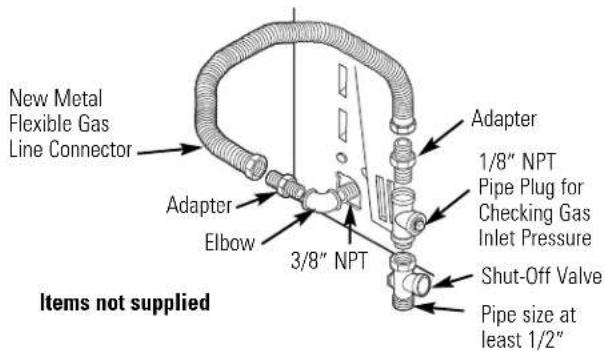
text_image
New Metal Flexible Gas Line Connector Adapter Elbow 3/8" NPT Items not supplied Adapter 1/8" NPT Pipe Plug for Checking Gas Inlet Pressure Shut-Off Valve Pipe size at least 1/2"B Attach the flexible metal gas line connector to the adapter.
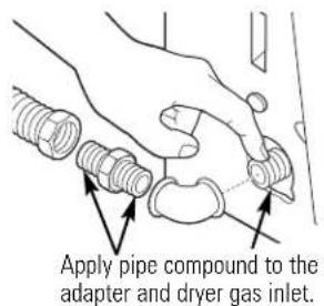
text_image
Apply pipe compound to the adapter and dryer gas inlet.C Tighten the flexible gas line connection, using two adjustable wrenches.
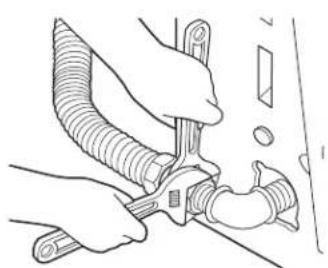
natural_image
Line drawing of hands using a tool to adjust or install a flexible hose (no text or symbols present)CONNECTING THE DRYER TO THE GAS SUPPLY (cont.)
D Install a 1/8" NPT plugged tapping to the dryer gas line shut-off valve for checking gas inlet pressure.
Install a flare union adapter to the plugged tapping.
NOTE: Apply pipe compound or Teflon® tape to the threads of the adapter and plugged tapping.
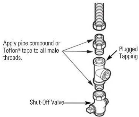
text_image
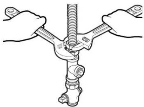
Apply pipe compound or Teflon® tape to all male threads. Plugged Tapping Shut-Off ValveE Tighten all connections, using two adjustable wrenches. Do not overtighten.
natural_image
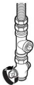
Illustration of hands connecting a mechanical pipe to a valve (no text or symbols present)F Open the gas shut-off valve.
TEST FOR LEAKS
⚠ WARNING – Never use an open flame to test for gas leaks.
Check all connections for leaks with soapy solution or equivalent.
Apply a soap solution. The leak test solution must not contain ammonia, which could cause damage to the brass fittings.
If leaks are found, close the valve, retighten the joint and repeat the soap test.

text_image
Open Gas ValveELECTRICAL CONNECTION INFORMATION FOR GAS DRYERS
A WARNING – To reduce the risk of fire, electrical shock and personal injury:
- Do not use an extension cord or an adapter plug with this appliance.
- The dryer must be electrically grounded in accordance with local codes and ordinances, or in the absence of local codes, in accordance with the NATIONAL ELECTRICAL CODE, ANSI/NFPA NO. 70.
ELECTRICAL REQUIREMENTS FOR GAS DRYERS
This appliance must be supplied with 120V, 60Hz, and connected to a properly grounded branch circuit, protected by a 15- or 20-amp circuit breaker or time-delay fuse.
If electrical supply provided does not meet the above specifications, it is recommended that a licensed electrician install an approved outlet.
A WARNING - This dryer is equipped with a three-prong (grounding) plug for your protection against shock hazard and should be plugged directly into a properly grounded three-prong receptacle. Do not cut or remove the grounding terminal from this plug.
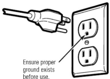
text_image
Ensure proper ground exists before use.If local codes permit, an external ground wire (not provided), which meets local codes, may be added by attaching to the green ground screw on the rear of the dryer, and to an alternate established ground.
Ensure proper ground exists before use.
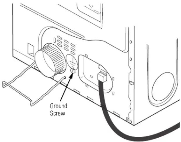
text_image
Ground ScrewCONNECTING AN ELECTRIC DRYER (skip for gas dryers)
TOOLS YOU WILL NEED
□Slip-joint pliers
□Phillips screwdriver
Flat-blade screwdriver
□Level
MATERIALS YOU WILL NEED

□4" dia. metal elbow
Gloves
☐ 3/4" strain relief (UL recognized)
Exhaust hood
☐4" duct clamps (2) or 4" spring clamps (2)
□Duct tape
□Safety glasses
☐Dryer power cord kit (not provided with dryer)
UL rated 120/240V, 30A with 3 or 4 prongs. Identify the plug type as per the house receptacle before purchasing line cord.

☐4" dia. metal duct (recommended)
☐4" dia., UL-listed flexible metal duct (if needed)
FOR YOUR SAFETY:
WARNING
Before making the electrical connection, turn off the circuit breaker(s) or remove the dryer's circuit fuse(s) at the electrical box. Be sure the dryer cord is unplugged from the wall. NEVER LEAVE THE ACCESS COVER OFF THE TERMINAL BLOCK.
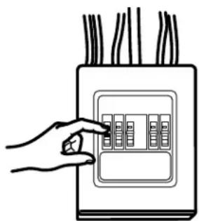
natural_image
Hand placing a button into an electrical outlet panel (no text or symbols visible)ELECTRICAL CONNECTION INFORMATION FOR ELECTRIC DRYERS
A WARNING - To reduce the risk of fire, electrical shock and personal injury:
- Do not use an extension cord or an adapter plug with this appliance.
- The dryer must be electrically grounded in accordance with local codes and ordinances or, in the absence of local codes, in accordance with the NATIONAL ELECTRICAL CODE, ANSI/NFPA NO. 70.
ELECTRICAL REQUIREMENTS FOR ELECTRIC DRYERS
This dryer must be connected to an individual branch circuit, protected by the required time-delay fuses or circuit breakers. A three- or four-wire, single-phase, 120/240V, 60Hz, 30-amp circuit is required.
If the electric supply does not meet the above specifications, then call a licensed electrician.
GROUNDING INSTRUCTIONS
This dryer must be connected to a grounded metal, permanent wiring system, or an equipment-grounding conductor must be run with the circuit conductors and connected to the equipment grounding terminal on the appliance.
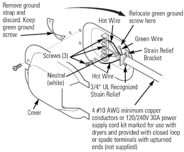
CONNECTING DRYER USING 4-WIRE CONNECTION (MUST BE USED FOR MOBILE HOME INSTALLATION)
NOTE: Since January 1, 1996, the National Electrical Code requires that new constructions utilize a
4-wire connection to an electric dryer. A 4-wire cord must also be used where local codes do not permit grounding through the neutral.
3-wire connection is NOT for use on new construction.
text_image
Remove ground strap and discard. Keep green ground screw Hot Wire Relocate green ground screw here Green Wire Strain Relief Bracket Screws (3) Neutral (white) Hot Wire 3/4" UL Recognized Strain Relief Cover 4 #10 AWG minimum copper conductors or 120/240V 30A power supply cord kit marked for use with dryers and provided with closed loop or spade terminals with upturned ends (not supplied)CONNECTING DRYER USING 4-WIRE CONNECTION (MUST BE USED FOR MOBILE HOME INSTALLATION) (cont.)
- Turn off the circuit breaker(s) (30 amp) or remove the dryer's circuit fuse at the electrical box.
- Be sure the dryer cord is unplugged from the wall receptacle.
- Remove the power cord cover located at the lower back.
- Remove and discard ground strap. Keep the green ground screw for Step 7.
- Install 3/4 in. UL-recognized strain relief to power cord entry hole. Bring power cord through strain relief.
- Connect power cord as follows:
A. Connect the 2 hot lines to the outer screws of the terminal block (marked L1 and L2).
B. Connect the neutral (white) line to the center of the terminal block (marked N).
- Attach ground wire of power cord with the green ground screw (hole above strain relief bracket). Tighten all terminal block screws (3) completely.
- Properly secure power cord to strain relief.
- Reinstall the cover.
If required, by local code, install external ground (not provided) to grounded metal, cold water pipe, or other established ground determined by a qualified electrician.
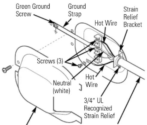
text_image
Green Ground Screw Ground Strap Hot Wire Strain Relief Bracket Screws (3) Neutral (white) Hot Wire 3/4" UL Recognized Strain Relief3 #10 AWG minimum copper conductors or 120/240V 30A power supply cord kit marked for use with dryers and provided with closed loop or spade terminals with upturned ends (not supplied)
- Turn off the circuit breaker(s) (30 amp) or remove the dryer's circuit fuse at the electrical box.
- Be sure the dryer cord is unplugged from the wall receptacle.
- Remove the power cord cover located at the lower back.
- Install 3/4-in. UL-recognized strain relief to power cord entry hole. Bring power cord through strain relief.
- Connect power cord as follows:
A. Connect the 2 hot lines to the outer screws of the terminal block (marked L1 and L2).
B. Connect the neutral (white) line to the center of the terminal block (marked N).
- Be sure ground strap is connected to neutral (center) terminal of block and to green ground screw on cabinet rear. Tighten all terminal block screws (3) completely.
- Properly secure power cord to strain relief.
- Reinstall the cover.
⚠ WARNING – To reduce the risk of fire or personal injury:
- This clothes dryer must be exhausted to the outdoors.
- Use only 4" rigid metal ducting for the home exhaust duct.
- Use only 4 " rigid metal or UL-listed flexible metal (semi-rigid or foil-type) duct to connect the dryer to the home exhaust duct. It must be installed in accordance with the instructions found in "Connecting the Dryer to House Vent" on page 26 of this manual.
- Do not terminate exhaust in a chimney, a wall, a ceiling, gas vent, crawl space, attic, under an enclosed floor, or in any other concealed space of a building.
- Never terminate the exhaust into a common duct with a kitchen exhaust system. A combination of grease and lint creates a potential fire hazard.
- Do not use duct longer than specified in the exhaust length table. Longer ducts can accumulate lint, creating a potential fire hazard.
- Never install a screen in or over the exhaust duct. This will cause lint to accumulate, creating a potential fire hazard.
- Do not assemble ductwork with any fasteners that extend into the duct. These fasteners can accumulate lint, creating a potential fire hazard.
- Do not obstruct incoming or exhausted air.
- Provide an access for inspection and cleaning of the exhaust system, especially at turns and joints. Exhaust system shall be inspected and cleaned at least once a year.
- This dryer comes ready for rear exhausting. If space is limited, use the instructions on pages 29–31 to exhaust directly from the sides or bottom of the cabinet.
EXHAUST SYSTEM CHECKLIST
HOOD OR WALL CAP
- Terminate in a manner to prevent back drafts or entry of birds or other wildlife.
- Termination should present minimal resistance to the exhaust airflow and should require little or no maintenance to prevent clogging.
- Never install a screen in or over the exhaust duct.
- Wall caps must be installed at least 12" above ground level or any other obstruction with the opening pointed down.
SEPARATION OF TURNS
- For best performance, separate all turns by at least 4 ft. of straight duct, including distance between last turn and dampened wall cap.
SEALING OF JOINTS
- All joints should be tight to avoid leaks. The male end of each section of duct must point away from the dryer.
- Do not assemble the ductwork with fasteners that extend into the duct. They will serve as a collection point for lint.
- Duct joints should be made air- and moisture-tight by wrapping the overlapped joints with duct tape or aluminum tape.
- Horizontal runs should slope down towards the outdoors 1/4" per foot.
INSULATION
- Ductwork that runs through an unheated area or is near air conditioning should be insulated to reduce condensation and lint buildup.
TOOLS AND MATERIALS YOU WILL NEED TO INSTALL EXHAUST DUCT
□Phillips-head screwdriver
☐Duct tape or duct clamp
☐ Drill with 1/8" drill bit (for bottom venting)
Hacksaw
☐Rigid or UL-listed flexible metal 4" (10.2 cm) duct
□Vent hood
EXHAUSTING THE DRYER (cont.)
CONNECTING THE DRYER TO HOUSE VENT
RIGID METAL TRANSITION DUCT
- For best drying performance, a rigid metal transition duct is recommended.
- Rigid metal transition ducts reduce the risk of crushing and kinking.
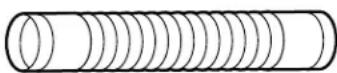
UL-LISTED FLEXIBLE METAL (SEMI-RIGID) TRANSITION DUCT
- If rigid metal duct cannot be used, then UL-listed flexible metal (semi-rigid) ducting can be used (Kit WX08X10077).
- Never install flexible metal duct in walls, ceilings, floors or other enclosed spaces.
- Total length of flexible metal duct should not exceed 8 feet (2.4 m).
- For many applications, installing elbows at both the dryer and the wall is highly recommended (see illustrations at right). Elbows allow the dryer to sit close to the wall without kinking and/or crushing the transition duct, maximizing drying performance.
- Avoid resting the duct on sharp objects.
UL-LISTED FLEXIBLE METAL (FOIL-TYPE) TRANSITION DUCT
- In special installations, it may be necessary to connect the dryer to the house vent using a flexible metal (foil-type) duct. A UL-listed flexible metal (foil-type) duct may be used ONLY in installations where rigid metal or flexible metal (semi-rigid) ducting cannot be used AND where a 4" diameter can be maintained throughout the entire length of the transition duct.
- In Canada and the United States, only the flexible metal (foil-type) ducts that comply with the "Outline for Clothes Dryer Transition Duct Subject 2158A" shall be used.
- Never install flexible metal duct in walls, ceilings, floors or other enclosed spaces.
- Total length of flexible metal duct should not exceed 8 feet (2.4 m).
- Avoid resting the duct on sharp objects.
- For best drying performance:
- Slide one end of the duct over the clothes dryer outlet pipe.
- Secure the duct with a clamp.
- With the dryer in its permanent position, extend the duct to its full length. Allow 2" of duct to overlap the exhaust pipe. Cut off and remove excess duct. Keep the duct as straight as possible for maximum airflow.
- Secure the duct to the exhaust pipe with the other clamp.
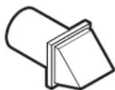
FOR TRANSITION VENTING (DRYER TO WALL), DO:
natural_image
Technical line drawing of a mechanical component or enclosure with no visible text or symbols- DO cut duct as short as possible and install straight into wall.
text_image
•DO wh ne Elbows• DO use elbows when turns are necessary.
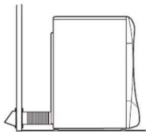
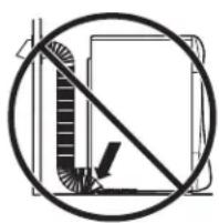
DO NOT:
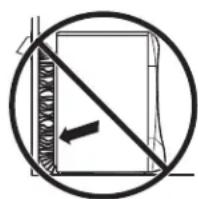
natural_image
Simple line drawing of a prohibition symbol (no text or labels)•DO NOT bend or collapse ducting. Use elbows if turns are necessary.
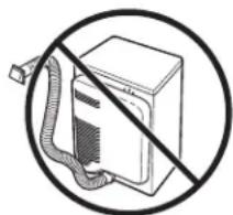
natural_image
Simple line drawing of a computer monitor with a diagonal line crossing through it, no text or symbols present.- DO NOT use excessive exhaust length. Cut duct as short as possible.
•DO NOT crush duct against the wall.
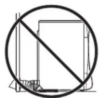
text_image
Diagram showing a diagonal line intersecting a vertical bar with a checkmark, indicating prohibition or restriction.•DO NOT set dryer on duct.
WARNING - USE ONLY METAL
4" DUCT. DO NOT USE DUCT LONGER THAN SPECIFIED IN THE EXHAUST LENGTH TABLE.
Using exhaust longer than specified length will:
- Increase the drying times and the energy cost.
- Reduce the dryer life.
- Accumulate lint, creating a potential fire hazard.
The correct exhaust installation is YOUR RESPONSIBILITY.
Problems due to incorrect installation are not covered by the warranty.
The MAXIMUM ALLOWABLE length of the exhaust system depends upon the type of duct, number of turns, the type of exhaust hood (wall cap) and all conditions noted below.
EXHAUST LENGTH
| RECOMMENDED MAXIMUM LENGTH | |
| Exhaust Hood Types | |
| Recommended Use | only for short-run installations |
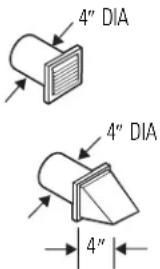 |  |
| No. of 90° Rigid Rigid Elbows Metal Metal | |
| 0 150 Feet 125 Feet1 135 Feet 115 Feet2 125 Feet 105 Feet3 115 Feet 95 Feet4 105 Feet 85 Feet5 95 Feet 75 Feet | |
EXHAUST SYSTEM CHECKLIST
HOOD OR WALL CAP
- Terminate in a manner to prevent back drafts or entry of birds or other wildlife.
- Termination should present minimal resistance to the exhaust airflow and should require little or no maintenance to prevent clogging.
- Never install a screen in or over the exhaust duct. This could cause lint buildup.
- Wall caps must be installed at least 12" above ground level or any other obstruction with the opening pointed down.
SEPARATION OF TURNS
For best performance, separate all turns by at least 4 ft. of straight duct, including the distance between the last turn and the exhaust hood.
TURNS OTHER THAN 90°
- One turn of 45^ or less may be ignored.
- Two 45^ turns should be treated as one 90^ turn.
• Each turn over 45^ should be treated as one 90^ turn.
SEALING OF JOINTS
- All joints should be tight to avoid leaks. The male end of each section of duct must point away from the dryer.
- Do not assemble the ductwork with fasteners that extend into the duct. They will serve as a collection point for lint.
- Duct joints can be made air- and moisture-tight by wrapping the overlapped joints with duct tape.
- Horizontal runs should slope down toward the outdoors 1/2" per foot.
INSULATION
Ductwork that runs through an unheated area or is near air conditioning should be insulated to reduce condensation and lint buildup.
EXHAUSTING THE DRYER (cont.)
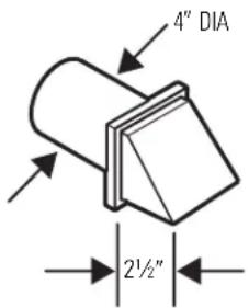
BEFORE YOU BEGIN
- Remove and discard existing plastic or metal foil duct and replace with UL-listed duct.
- Remove any lint from the wall exhaust opening.
text_image
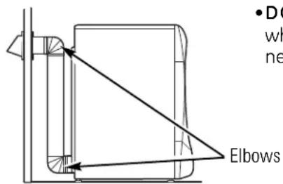
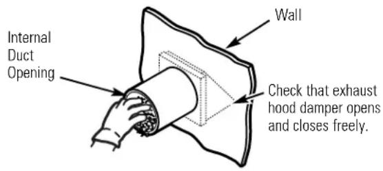
Internal Duct Opening Wall Check that exhaust hood damper opens and closes freely.RECOMMENDED CONFIGURATION TO MINIMIZE EXHAUST BLOCKAGE
Using duct elbows will prevent duct kinking and collapsing.
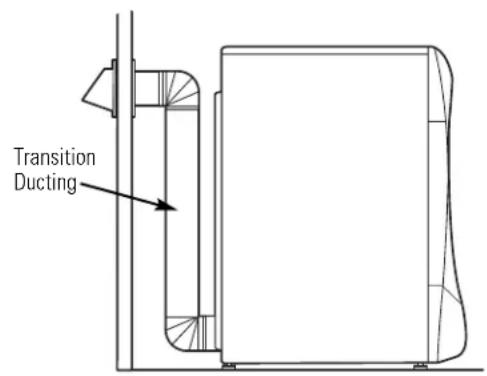
text_image
Transition DuctingSTANDARD REAR EXHAUST
We recommend that you install your dryer before installing your washer. This will permit direct access for easier exhaust connection.
Slide the end of the exhaust duct on the back of the dryer and secure with duct tape or a hose clamp.
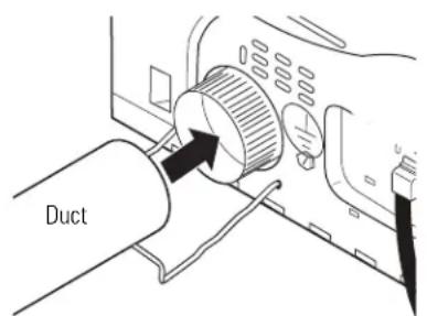
text_image
DuctNOTE: We strongly recommend using rigid metal exhaust duct.
- For straight-line installation, connect the dryer exhaust to the wall, using duct tape.
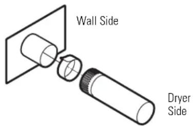
text_image
Wall Side Dryer SideSIDE VENTING:
Dryer Exhaust to right of cabinet for Electric models only.
Dryer Exhaust to left of cabinet for Gas and Electric models.
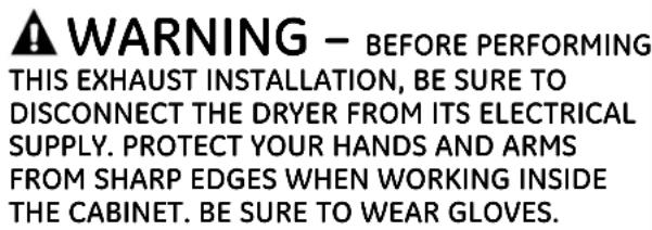
text_image
WARNING - BEFORE PERFORMING THIS EXHAUST INSTALLATION, BE SURE TO DISCONNECT THE DRYER FROM ITS ELECTRICAL SUPPLY. PROTECT YOUR HANDS AND ARMS FROM SHARP EDGES WHEN WORKING INSIDE THE CABINET. BE SURE TO WEAR GLOVES.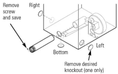
text_image
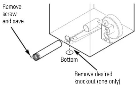
Remove screw and save Right Bottom Left Remove desired knockout (one only)Detach and remove the bottom, right or left side knockout as desired. Remove the screw inside the dryer exhaust duct and save. Pull the duct out of the dryer.
text_image
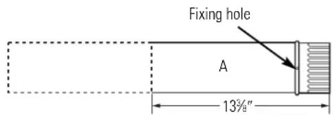
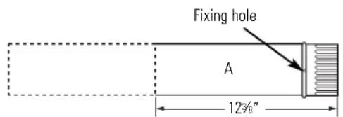
Fixing hole A 13¾"Cut the duct as shown and keep portion A.
TAB LOCATION
text_image
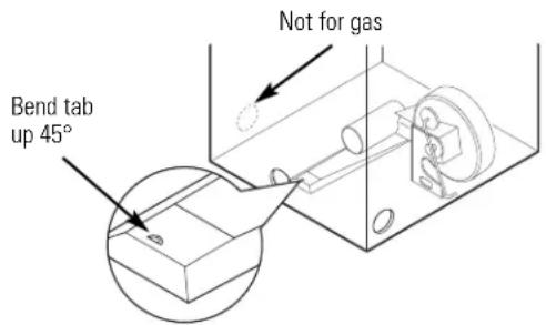
Bend tab up 45° Not for gasThrough the rear opening, locate the tab in the middle of the appliance base. Lift the tab to about 45^ , using a flat-blade screwdriver.
ADDING A NEW DUCT
text_image
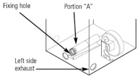
Fixing hole Portion "A" Left side exhaustReconnect the cut portion (A) of the duct to the blower housing. Make sure that the shortened duct is aligned with the tab in the base. Use the screw saved previously to secure the duct in place through the tab on the appliance base.
ADDING ELBOW AND DUCT FOR EXHAUST TO LEFT OR RIGHT SIDE OF CABINET
text_image
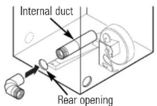
Internal duct Rear opening- Insert the 4" elbow through the rear opening and connect the elbow to the dryer internal duct.
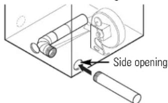
text_image
Side opening- Insert the 4" duct through the side opening and connect it to the elbow.
A CAUTION: Do not pull or damage the electrical wires and do not remove the vinyl cover from the electrical components inside the dryer when inserting the duct. A slight interference may occur between the exhaust and the wire components.
EXHAUSTING THE DRYER (cont.)
SIDE VENTING (cont.)
ADDING ELBOW AND DUCT FOR EXHAUST TO LEFT OR RIGHT SIDE OF CABINET (cont.)
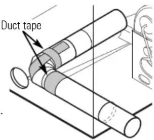
- Apply duct tape as shown on the joint between the dryer internal duct and the elbow, and also the joint between the elbow and the side duct.
text_image
Duct tapeCAUTION:
Internal duct joints must be secured with tape; otherwise, they may separate and cause a safety hazard.
ADDING COVER PLATE TO REAR OF CABINET (SIDE EXHAUST)
text_image
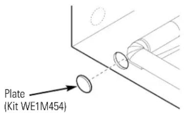
Plate (Kit WE1M454)Connect standard metal elbows and ducts to complete the exhaust system. Cover back opening with a plate (Kit WE1M454) available from your local service provider. Place dryer in final location.
WARNING - NEVER LEAVE THE BACK OPENING WITHOUT THE PLATE. (Kit WE1M454)
BOTTOM VENTING:
Dryer Exhaust to the bottom of cabinet for Gas and Electric models.
WARNING - BEFORE PERFORMING THIS EXHAUST INSTALLATION, BE SURE TO DISCONNECT THE DRYER FROM ITS ELECTRICAL SUPPLY. PROTECT YOUR HANDS AND ARMS FROM SHARP EDGES WHEN WORKING INSIDE THE CABINET. BE SURE TO WEAR GLOVES.
text_image
Remove screw and save Bottom Remove desired knockout (one only)Remove the screw inside the dryer exhaust duct and save. Pull the duct out of the dryer. Detach and remove the bottom knockout.
text_image
Fixing hole A 12%"Cut the duct as shown and keep portion A.
BOTTOM VENTING (cont.)
ADDING A NEW DUCT
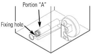
- Reconnect the cut portion A of the duct to the blower housing.
- Tape the elbow in a 90-degree position to prevent rotation.
- Insert the elbow through the rear hole and connect it to portion A. Rotate the elbow through the bottom opening.
text_image
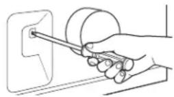
Portion "A" Fixing hole- While holding down the pipe and elbow, using your hand through the rear opening, drill a 1/8" hole through the bottom tab hole and the pipe as shown in the illustration.
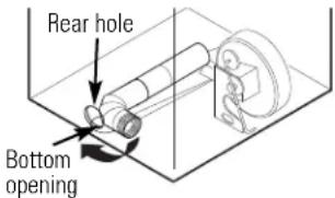
text_image
Rear hole Bottom opening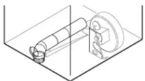
natural_image
Technical line drawing of a mechanical assembly inside a transparent container (no text or symbols)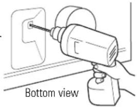
natural_image
Hand using a drill bit to apply electrical socket to a wall socket (no text or symbols visible)NOTE: Make sure the hole is drilled all the way through the elbow and pipe.
CAUTION: Be sure not to pull or damage the electrical wires inside the dryer when inserting the duct.
- While still holding down the pipe and elbow from the rear opening, screw the pipes in place with the previously saved screw.
- Apply duct tape as shown on the joint between the dryer internal duct and the elbow.
NOTE: Make sure the tape covers the screw hole in portion A where it connects to the elbow.
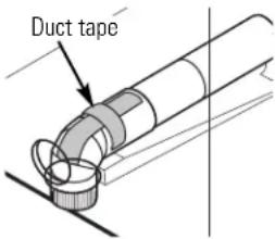
text_image
Duct tapeCAUTION: Internal duct joints must be secured with tape; otherwise, they may separate and cause a safety hazard.
Dryer Exhaust to the bottom of cabinet for Gas and Electric models.
ADDING COVER PLATE TO REAR OF CABINET (BOTTOM EXHAUST)
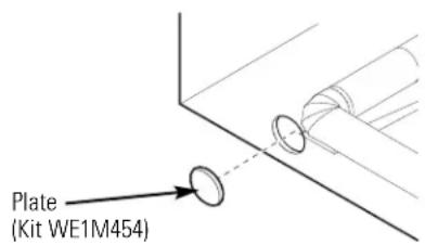
text_image
Plate (Kit WE1M454)Connect standard metal elbows and ducts to complete the exhaust system. Cover back opening with a plate (Kit WE1M454) available from your local service provider. Place dryer in final location.
WARNING - NEVER LEAVE THE BACK OPENING WITHOUT THE PLATE. (Kit WE1M454)
FINAL SETUP
① LEVEL THE DRYER
Stand the dryer upright near the final location and adjust the four leveling legs at the corners to ensure that the dryer is level from side to side and front to rear.
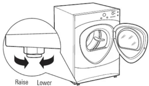
text_image
Raise Lower② ATTACH SERIAL CABLE
Attach the serial cable for washer and dryer connection to the serial port on the back of the dryer.
Attach the other end of the cable to the washer before pushing the washer into its final position.
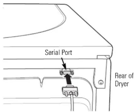
text_image
Serial Port Rear of Dryer3 PLUG DRYER IN
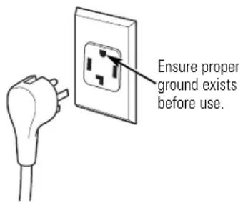
text_image
Ensure proper ground exists before use.4 GROUNDING INSTRUCTIONS
This appliance must be grounded. In the event of malfunction or breakdown, grounding will reduce the risk of electric shock by providing a path of least resistance for electric current. This appliance is equipped with a cord having an equipment-grounding conductor and a grounding plug. The plug must be plugged into an appropriate outlet that is properly installed and grounded in accordance with all local codes and ordinances.
5 DRYER STARTUP
Press the POWER button.
NOTE: If the dryer has been exposed to temperatures below freezing for an extended period of time, allow it to warm up before pressing POWER. Otherwise, the display will not come on. The dryer is now ready for use.
SERVICING
WARNING – Label all wires prior to disconnection when servicing controls. Wiring errors can cause improper and dangerous operation after servicing/installation.
For replacement parts and other information, refer to the back cover for servicing phone numbers.
REVERSING THE DOOR SWING (if desired)
IMPORTANT NOTES
- Read the instructions all the way through before starting.
- Handle parts carefully to avoid scratching paint.
- Provide a non-scratching work surface for the doors.
- Set screws down by their related parts to avoid using them in the wrong places.
- All screws must be hand-tightened.
- Normal completion time to reverse the door swing is 30–60 minutes.
IMPORTANT: Once you begin, do not move the cabinet until door-swing reversal is completed.
These instructions are for changing the hinges from the right side to the left side—if you ever want to switch them back to the right side, follow these same instructions and reverse all references to the left and right.
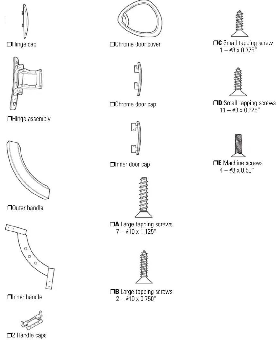
STANDARD REVERSIBILITY KIT
Chrome door cap
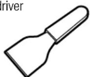
☐Phillips-head screwdriver
☐Putty knife or thin-blade screwdriver
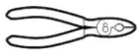
□Pliers
REVERSING THE DOOR SWING (if desired)
DOOR PARTS
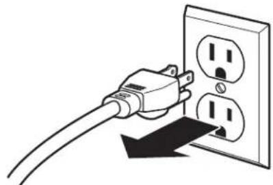
BEFORE YOU START
Unplug the dryer from its electrical outlet.
natural_image
Illustration of a plug inserted into an open electrical outlet with three socket slots (no text or symbols)① REMOVE THE DOOR ASSEMBLY
Remove the side hinge cap by opening the dryer door and removing the screw from behind the hinge (#8 x .375" tapping screw). Then using your hand, pop the hinge cap off the dryer.
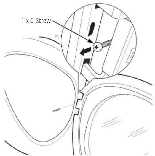
text_image
1 x C Screw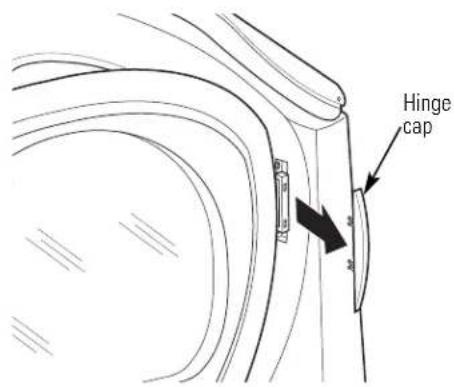
text_image
Hinge cap① REMOVE THE DOOR ASSEMBLY (cont.)
Hold the door and remove the 2 hinge screws (#10 x 0.75" tapping screws). Pull the door away from the dryer front panel.
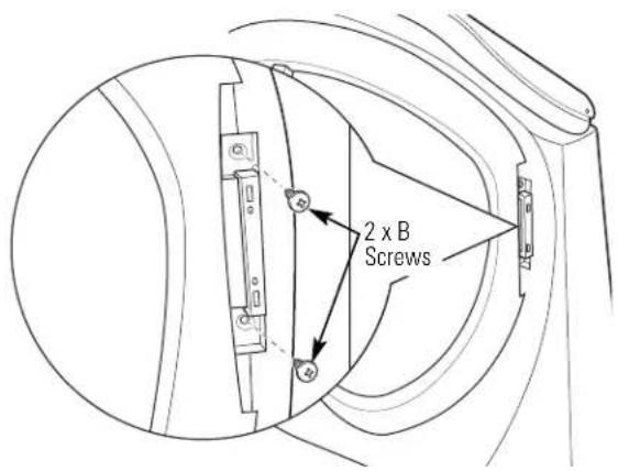
text_image
2 x B Screws② DISASSEMBLE THE DOOR ASSEMBLY
Lay the door down on a soft, protected, flat surface so that the inner part faces upward (door resting on the handle side).
Remove the 7 screws (#10 x 1.125" tapping screws) located around the perimeter of the door.
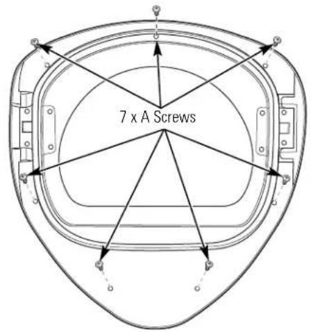
text_image
7 x A ScrewsTurn the door assembly over and separate the chrome cover from the inner door. Put the inner door aside on a soft, protected flat surface.
REVERSING THE DOOR SWING (if desired)
③ REVERSE DOOR HANDLE AND CAPS
A Lay the chrome cover down on a soft, protected, flat surface so that the inner part faces upward (resting on the handle side). Disassemble the door cap from the chrome cover on the handle side by removing 2 screws (#8 × 0.625" tapping screws).
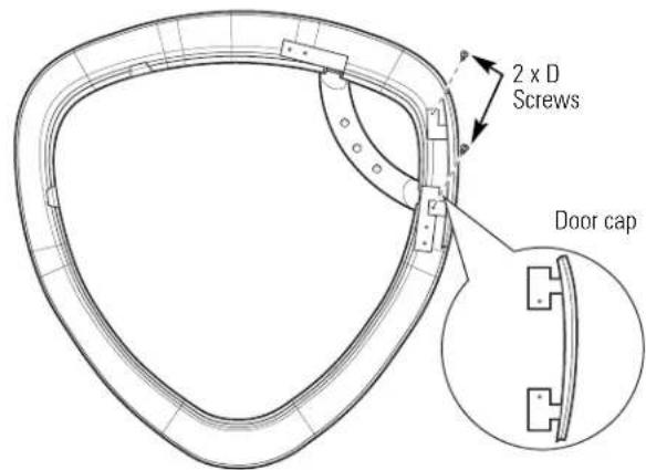
text_image
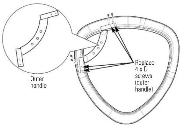
2 x D Screws Door capB Disassemble the inner handle from the outer handle by removing 3 screws (#8 × 0.625" tapping screws). Disassemble the outer handle from the chrome cover by removing 4 screws (#8 × 0.625" tapping screws).
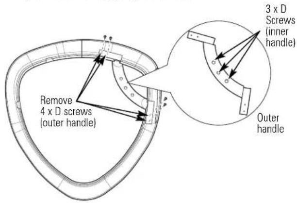
text_image
Remove 4 x D screws (outer handle) 3 x D Screws (inner handle) Outer handle③ REVERSE DOOR HANDLE AND CAPS (CONT.)
C Pop the 2 handle caps out toward you and reassemble on the opposite side of the chrome cover, where you removed the outer handle.
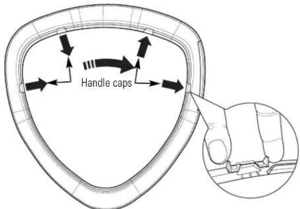
text_image
Handle capsD Assemble the outer handle onto the opposite side of the chrome cover, using 4 screws (#8 × 0.625" tapping screws).
text_image
Outer handle Replace 4 x D screws (outer handle)3 REVERSE DOOR HANDLE AND CAPS (CONT.)
E Reassemble the inner handle to the outer handle, using 3 screws (#8 × 0.625" tapping screws).
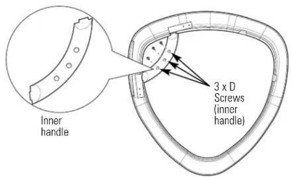
text_image
Inner handle 3 x D Screws (inner handle)F Assemble the new right-side door cap (from reversibility kit), using 2 screws (#8 × 0.625" tapping screws).
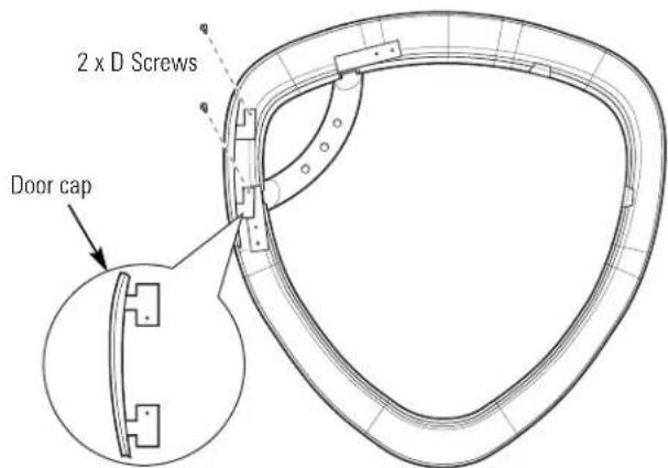
text_image
2 x D Screws Door capPut the chrome cover aside on a soft, protected flat surface.
4 REVERSE HINGE AND CAPS
- Lay the inner door down on a soft, protected flat surface so that the inner part faces up.
- Remove the 2 black plug buttons on the opposite side of the hinge, using a putty knife or thin-blade screwdriver.
- Disassemble the inner door cap from the inner door by removing 2 screws ( 8 × 0.75'' tapping screws).
- Disassemble the hinge from the inner door by removing 4 screws (#8-32 x 0.50" machine screws).
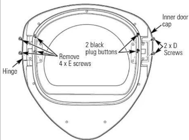
text_image
Hinge Remove 4 x E screws 2 black plug buttons Inner door cap 2 x D Screws- Assemble the hinge to the opposite side of the inner door, using 4 screws (#8-32 x 0.50" machine screws).
- Assemble the new inner door cap (from reversibility kit) on the opposite side of the hinge, using 2 screws ( 8 × 0.75'' tapping screws).
• Install the 2 black plug buttons on the opposite side of the hinge in the 2 remaining holes.
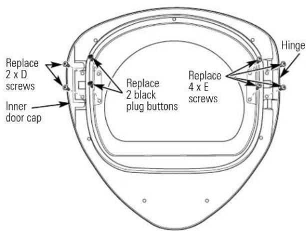
text_image
Replace 2 x D screws Inner door cap Replace 2 black plug buttons Replace 4 x E screws HingeREVERSING THE DOOR SWING (if desired)
⑤ REASSEMBLE DOOR ASSEMBLY
Turn the inner door over and place on a soft, protected flat surface so that the inner part is facing down. Assemble the chrome cover to the inner door by placing them together.
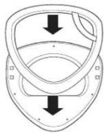
natural_image
Pure diagram of a mechanical component with two downward arrows indicating direction (no text or symbols)Flip the door assembly over and assemble, using 7 screws (#10 × 1.125" tapping screws).
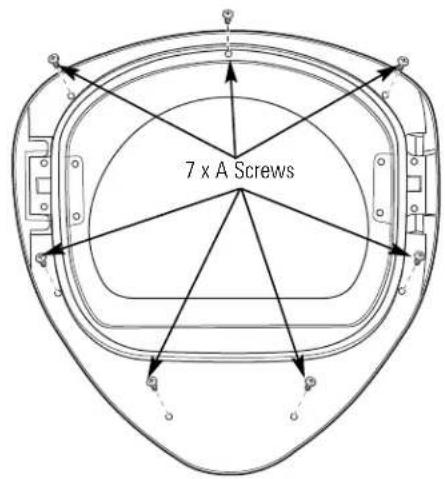
text_image
7 x A Screws6 REVERSE FRONT PANEL PLUG BUTTONS AND STRIKE PLATE
Remove the 2 plug buttons on the dryer front panel, using a putty knife or other flat tool as shown, and reinstall on the opposite side. Switch the strike bracket and its cover by removing 2 screws (#8 × 0.625" tapping screws) for each and reinstalling on opposite sides.
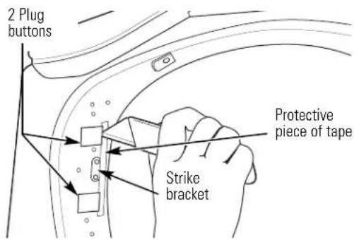
text_image
2 Plug buttons Protective piece of tape Strike bracketNOTE: Apply a protective piece of tape to the side of the plug button where the putty knife blade will be inserted to prevent scratching.
⑦ REINSTALL DOOR ASSEMBLY
Place the door back on the dryer front panel, making sure the latch is engaged and the hinge is sitting in the two openings in the dryer front. Assemble the door to the front cabinet, using 2 screws (#10 × 0.75" tapping screws).
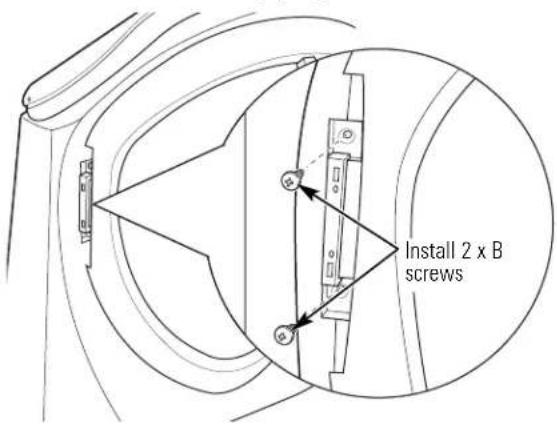
text_image
Install 2 x B screwsInstall the new left-hand hinge cap (from the reversibility kit) onto the hinge, by opening the dryer door and screwing the hinge cap into place.
NOTE: Save the remaining caps and covers in case you want to reverse the hinge again.
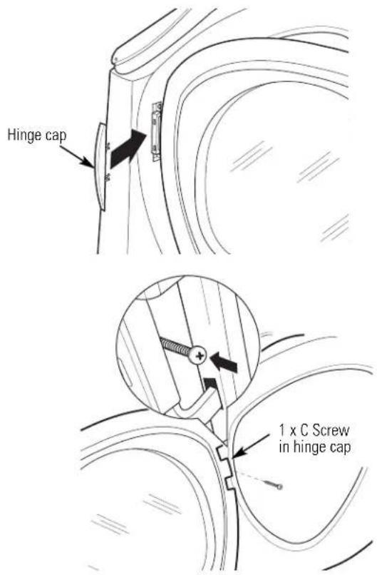
text_image
Hinge cap 1 x C Screw in hinge capSTACKING THE WASHER AND DRYER (if desired)
BEFORE YOU BEGIN
Read these instructions completely and carefully.
- IMPORTANT – Save these instructions for local electrical inspector's use.
- IMPORTANT - Observe all governing codes and ordinances.
- Note to Installer – Be sure to leave these instructions with the Consumer.
- Note to Consumer – Keep these instructions for future reference.
- Service must be performed by a qualified installer.
- Proper installation is the responsibility of the installer.
FOR YOUR SAFETY:
⚠ WARNING -
- Electric Shock Hazard. Disconnect power before installing. Failure to do so could result in serious injury or death.
- Potential Personal Injury. More than two people are recommended to lift the dryer into position because of its weight and size. Failure to do so could result in personal injury or death.
- Avoid Tipping and Rupture of Utility Services. Dryer must be securely attached to the washer. DO NOT place the washer on top of the dryer. Failure to do so could result in personal injury/death or property damage.
- Mobile Home or Manufactured Home Installation – Stacking of a gas dryer is not permitted in a mobile home or manufactured home.
MINIMUM CLEARANCE OTHER THAN ALCOVE OR CLOSET INSTALLATION
Minimum clearance to combustible surfaces and for air opening are: 0" both sides, 1" front and 3" rear. Consideration must be given to provide adequate clearance for installation and service.
REQUIREMENTS FOR ALCOVE OR CLOSET INSTALLATION
- Your dryer is approved for installation in an alcove or closet, as stated on a label on the dryer back.
- The dryer MUST be vented to the outdoors. See the EXHAUSTING THE DRYER section.
- Minimum clearance between dryer cabinet and adjacent walls or other surfaces is:
0" either side 3" front and rear
- Minimum vertical space from floor to overhead shelves, cabinets, ceilings, etc., is 52".
- Closet doors must be louvered or otherwise ventilated and have at least 60 square inches of open area equally distributed. If the closet contains both a washer and a dryer, doors must contain a minimum of 120 square inches of open area equally distributed.
- The closet should be vented to the outdoors to prevent gas pocketing in case of gas in the supply line.
- No other fuel-burning appliance shall be installed in the same closet with the dryer (gas models only).
NOTE: WHEN THE EXHAUST DUCT IS LOCATED AT THE REAR OF THE DRYER, MINIMUM CLEARANCE FROM THE WALL IS 5.5 INCHES.
STACKING THE WASHER AND DRYER (if desired) (cont.)
KIT CONTENTS
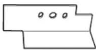
Right hand bracket
☐ 4 #12 x 1" screws
□Left hand bracket

☐ 4 #8 x 1/2" screws
□4 rubber pads
TOOLS YOU WILL NEED
□Phillips screwdriver
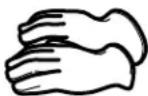
Gloves
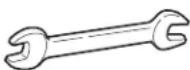
Open-ended wrench
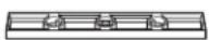
Level
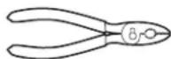
□Pliers
INSTALLATION PREPARATION
Remove the packaging.
Flatten the product carton to use as a pad to lay the dryer down on its side. Continue using the carton to protect the finished floor in front of the installation location.
INSTALLING THE STACK BRACKET KIT

REMOVE THE DRYER LEVELING LEGS
A. Carefully lay the dryer on its side. Use the packing material so you don't scratch the finish on the dryer.
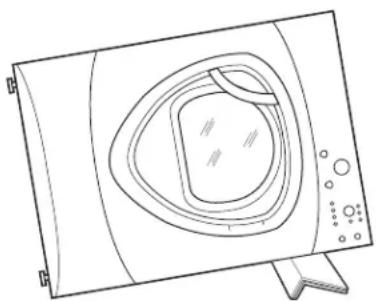
natural_image
Line drawing of a washing machine with control panel and buttons (no text or symbols)B. Use an open-end wrench or pliers to remove the dryer leveling legs.
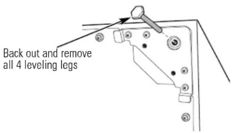
text_image
Back out and remove all 4 leveling legs
INSTALL RUBBER PADS TO DRYER BASE
Locate the 4 rubber pads in the parts package. Remove the adhesive backing and firmly place over on the bracket where you removed the leveling legs.
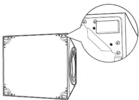
natural_image
Technical line drawing of a rectangular electronic device with mounting holes and a close-up inset showing internal components (no text or symbols)3 INSTALL BRACKET TO DRYER
A. Align the holes in the left bracket with the holes in the bottom left corner of the dryer. Use a Phillips screwdriver to install the 2 #12 x 1" tapping screws.
B. Repeat the above step with the right bracket on the bottom right corner of the dryer.
C. Set the dryer upright.
NOTE: Make sure to set the dryer on a piece of packing material so the brackets that are attached to the bottom of the dryer do not damage the floor.
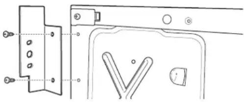
natural_image
Technical line drawing of a door handle and bracket assembly (no text or symbols)4 INSTALL DRYER AND BRACKET ON WASHER
A. Lift the dryer on top of the washer. Be careful not to scratch the top of the washer with the brackets. Protect the washer control panel with cardboard or other protection. Be sure to lift the dryer high enough to clear the washer control panel.
WARNING – Potential
Personal Injury. More than two people are recommended to lift the dryer into position because of its weight and size. Failure to do so could result in personal injury or death.
B. Align the holes in the bracket with the holes in the back of the washer. Using a Phillips screwdriver, attach the 2 #8 × 1/2" tapping screws. Repeat on both sides of the washer.
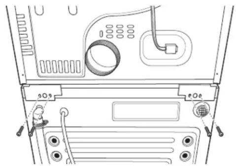
natural_image
Diagram of a computer rear panel showing internal components including a coiled cable, drive, and ventilation slots (no text or labels)5 FINALIZE THE INSTALLATION
A. Refer to the washer Installation Instructions to complete the washer installation.
B. Refer to the dryer Installation Instructions to complete the dryer installation.
C. Carefully slide or walk the stacked washer and dryer into place. Use felt pads or other sliding device to assist moving and to protect flooring.
WARNING – Potential Personal Injury. Do not push on the dryer once installed to top of the washer. Pushing on the dryer may result in pinched fingers.
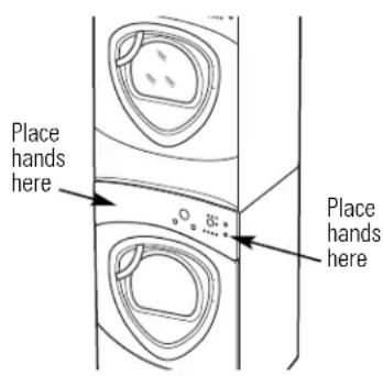
text_image
Place hands here Place hands hereINSTALLING THE PEDESTAL (if desired)
CAUTION — Due to the size and weight of these products, and to reduce the risk of personal injury or damage to the product, TWO PEOPLE ARE REQUIRED FOR PROPER INSTALLATION.
KIT CONTENTS
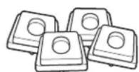
□4 Support pads
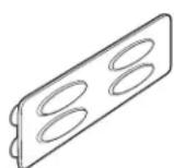
□Drawer divider
□4 Mounting screws
TOOLS YOU WILL NEED
□Phillips-head screwdriver
☐7 mm Socket wrench
☐ 9/16" Open-end wrench or adjustable wrench
INSTALLATION PREPARATION
Remove the packaging.
The drawer divider is taped at the top of the shipping carton. Remove the divider and set aside for final installation.
Flatten the product carton to use as a pad to lay the washer or dryer down on its side. Continue using the carton to protect the finished floor in front of the installation location.
1 REMOVE THE LEVELING LEGS
A Carefully lay the washer or dryer on its side to access the leveling legs on the bottom of the appliance.
IMPORTANT: Do not lay the washer or dryer on its back! Do not remove the shipping bolts on the back side of the washer. The bolts must remain in place until the washer is returned to an upright position.
B Use an open-end wrench to remove the washer or dryer leveling legs.

text_image
Back out and remove all 4 leveling legs2 PREPARE THE PEDESTAL
A Pull the drawer out as far as it will go.
B Remove screws from drawer slides. Slide drawer out of the base and set aside.
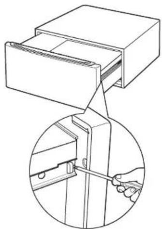
natural_image
Technical line drawing of a mechanical device with an inset showing a hand using a tool to adjust or install a component (no text or symbols present)FOR DRYERS ONLY:
C Locate the 4 support pads from the parts package. Each pad has 2 protrusions that fit into the holes on top of the pedestal. Press the rubber pads into each set of corner holes on the top of the pedestal as shown.
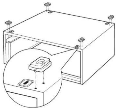
natural_image
Technical line drawing of a mechanical assembly with mounting holes and a circular component (no text or symbols)NOTE: The support pads should be installed on the dryer only. DO NOT INSTALL THESE PADS ON THE WASHER PEDESTAL.
3 INSTALL THE PEDESTAL TO THE WASHER OR DRYER
A Place the pedestal against the bottom of the unit. Check to be sure the drawer front is at the front of the washer.
B Align the holes in the pedestal with the holes in the bottom of the unit. Use a Phillips screwdriver to install the 4 bolts through the pedestal and into the unit—do not tighten.
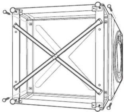
natural_image
Technical line drawing of a mechanical frame with diagonal braces and mounting holes (no text or symbols)C Slide the pedestal toward the unit, until it is aligned front to back. Use a 7 mm socket wrench to securely tighten the bolts.
INSTALLING THE PEDESTAL (if desired) (cont.)
4 LEVEL THE WASHER OR DRYER
A Stand the washer or dryer upright. Move it close to its final location.
B Make sure that the washer or dryer is level by placing a level on top. Check side to side and front to back.
C Use an open ended wrench to adjust the legs in and out. Tighten the lock nut against the bottom of the pedestal.
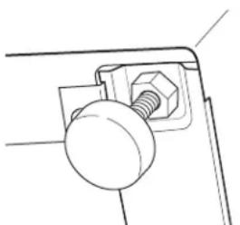
natural_image
Technical line drawing of a mechanical clamp or bracket with a spherical component (no text or symbols)NOTE: To minimize vibration, the locking nuts must be tight.
6 REMOVE SHIPPING SCREWS
Remove the 4 shipping screws on the back side of the washer.
7 FINALIZE THE INSTALLATION
Refer to the washer or dryer Installation Instructions to complete the installation.
5 REINSTALL THE DRAWER
A Check to be sure the slides are closed.
B Slide the drawer into the opening. Align the drawer supports to the slides on each side.
C Reinstall the original screws into each drawer slide. Tighten both screws.
D Open the drawer fully. Slide drawer divider into slots in the center of the drawer. The drawer should slide smoothly when you push it closed.
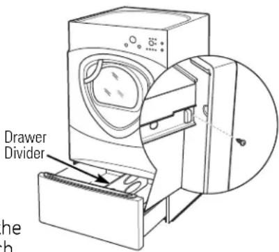
text_image
Drawer Divider the h
Troubleshooting Tips Save time and money! Review the charts on the following pages, or visit GEAppliances.com. You may not need to call for service.
PROBLEM Possible Causes What To Do
| Dryer shakes or makes noise | Some shaking/noise is normal. Dryer may be sitting unevenly | ·Move dryer to an even floor space, or adjust leveling legs as necessary until even. |
| Clothes take too long to dry dryer venting is correct. | Improper or obstructed ducting | ·Check the Installation Instructions to make sure the ·Make sure ducting is clean, free of kinks and unobstructed. ·Check to see if outside wall damper operates easily. |
| Improper sorting ·Separate heavy items from lightweight items (generally, a well-sorted washer load is a well-sorted dryer load). | ||
| Large loads of heavy fabrics ·Large, heavy fabrics contain more moisture and take (like beach towels) longer to dry. Separate large, heavy fabrics into smaller loads to speed drying time. | ||
| Controls improperly set ·Match control settings to the load you are drying. | ||
| Lint filter is full | ·Clean lint filter before every load. | |
| Blown fuses or tripped circuit breaker | ·Replace fuses or reset circuit breakers. Since most dryers use 2 fuses/breakers, make sure both are operating. | |
| Overloading/combining loads | ·Do not put more than one washer load in the dryer at a time. | |
| Underloading | ·If you are drying only one or two items, add a few items to ensure proper tumbling. | |
| The DRY dryness level was chosen but load is still damp | Load consists of a mixture of heavy and light fabrics | ·When combining heavy and light fabrics in a load, choose MORE DRY. |
| Exhaust system is blocked | ·Inspect and clean exhaust system. | |
| Control pads not responding | Controls accidentally put in service mode | ·Press START/PAUSE. |
| Controls accidentally put in lock mode | ·Hold the LOCK button for 3 seconds to unlock the dryer. | |
| Controls performed an ·Reset the in-house breaker. incorrect operation | ||
| Dryer doesn't start | Control panel is “asleep” | ·This is normal. Press POWER to activate the control panel. |
| Dryer is unplugged | ·Make sure the dryer plug is pushed completely into the outlet. | |
| Fuse is blown/circuit breaker is tripped | ·Check the building's fuse/circuit breaker box and replace fuse or reset breaker. NOTE: Electric dryers use two fuses or breakers. | |
| Dryer was accidentally paused when starting Delay Start | ·If the light on the START/PAUSE button is flashing, the dryer is paused. Press START/PAUSE to restart the countdown. | |
| No numbers displayed during cycle, only lights | Dryer is continuously monitoring the amount of moisture in the clothes | ·This is normal. When the dryer senses a low level of moisture in the load, the dryer will display the dry time remaining. |
Before you call for service...
| PROBLEM Possible Causes What To Do | ||
| Time Remaining The estimated time may change • This is normal.jumped to a when a smaller load than usuallower number is drying | ||
| Cannot make a selection and the dryer beeps twice trying to select is incompatible with the chosen dry cycle | The DRYNESS LEVEL, TEMP or OPTION that you are | • This is normal. |
| Dryer is running but 00 is displayed in Time Remaining | The EXTEND TUMBLE option was chosen | • This is normal. During extended tumbling, the time remaining is not displayed. The extended tumbling option lasts approximately 20 minutes. |
| Clean Lint Filter (message) | POWER button was activated | • Press START/PAUSE to begin a dry cycle and the message will disappear. |
| Dryer doesn't heat | Fuse is blown/circuit breaker is tripped; the dryer may tumble but not heat | • Check the building's fuse/circuit breaker box and replace both fuses or reset both breakers. Your dryer may tumble if only one fuse is blown or one breaker tripped. |
| Gas service is off | • Make sure gas shutoff at dryer and main shutoff are fully open. | |
| LP gas supply tank is empty or there has been a utility interruption of natural gas (gas models) | • Refill or replace tank. Dryer should heat when utility service is restored. | |
| Inconsistent drying times | Type of heat | • Drying time will vary according to the type of heat used. If you recently changed from an electric to a gas (natural or LP) dryer, or vice versa, the drying time could be different. |
| Type of load and drying conditions | • The load size, types of fabric, wetness of clothes and the length and condition of the exhaust system will affect drying times. | |
| Glow at the rear of the drum | Heaters behind the drum | • This is normal. Under certain drying conditions and room ambient lighting, the glow of the heaters may be visible at the rear of the drum. |
| Clothes are still wet and dryer shut off after a short time | The door was opened mid-cycle. The load was then removed from the dryer and a new load put in without selecting a new cycle | • A dry cycle must be reselected each time a new load is put in. |
| Small load | • When drying 3 items or less, choose SPEED DRY or TIMED DRY. | |
| Load was already dry except for collars and waistbands | • Choose SPEED DRY or TIMED DRY to dry damp collars and waistbands. In the future, when drying a load with collars and waistbands, choose MORE DRY. | |
| Dryer is not level | • Move dryer to an even floor space or adjust leveling legs as necessary until even. | |
| Clothes are wrinkled | Overdrying | • Select a shorter drying time.• Remove items while they still hold a slight amount of moisture. Select a LESS DRY or DAMP setting. |
| Letting items sit in dryer after cycle ends | • Remove items when cycle ends and fold or hang immediately, or use the EXTEND TUMBLE option. | |
| Overloading | • Separate large loads into smaller ones. | |
| Clothes shrink | Some fabrics will naturally shrink when washed. Others can be safely washed, but will shrink in the dryer | To avoid shrinkage, follow garment care labels exactly.Some items may be pressed back into shape after drying.If you are concerned about shrinkage in a particular item, do not machine wash or tumble dry it. |
| Greasy spots on clothes | Improper use of fabric softener | Follow directions on fabric softener package. |
| Drying dirty items Use your dryer to dry only clean items. Dirty items can with clean ones stain clean items and the dryer. | ||
| Clothes were not completely clean Sometimes stains which cannot be seen when the clothes are wet appear after drying. Use proper washing procedures before drying. | ||
| Lint on clothes | Lint filter is full | Clean lint screen before each load. |
| Improper sorting | Sort lint producers (like chenille) from lint collectors (like corduroy). | |
| Static electricity can attract lint | See suggestions in this section under STATIC. | |
| Overloading | Separate large loads into smaller ones. | |
| Paper, tissue, etc., left in pockets | Empty all pockets before laundering clothes. | |
| Static occurs | No fabric softener was used | Try a fabric softener.Bounce® Fabric Conditioner Dryer Sheets have been approved for use in all GE Dryers when used in accordance with the manufacturer's instructions. |
| Overdrying | Try a fabric softener.Adjust setting to LESS DRY or DAMP. | |
| Synthetics, permanent press and blends can cause static | Try a fabric softener. | |
| Collars and waistbands still wet at end of cycle | The dryness monitor senses that the body of the clothes is dry | Choose SPEED DRY or TIMED DRY to dry damp collars and waistbands. In the future, when drying a load with collars and waistbands, choose MORE DRY. |
| Slight variation in metallic color | This is normal | Due to the metallic properties of paint used for this unique product, slight variations of color may occur due to viewing angles and lighting conditions. |
| Door is too foggy to see clothes during a steam cycle | Steam condenses on inner door | This is normal. |
| Water seen on inside of door and top of lint filter when opening door after steam cycle | Steam condenses on these surfaces | This is normal. |
| Small areas on clothes are damp after steam cycle | Steam condenses on inner drum | Select a shorter cycle. |
| Cycle or cycle time selected too long for size of load | Manually reduce cycle time for given cycle. | |
Before you call for service...
| PROBLEM Possible Causes What To Do | ||
| Small amount of water on floor in front of dryer | Inadequate load size for steam cycle selected, excess steam condenses inside cabinet and leaks out | Select a shorter cycle. Manually reduce cycle time for given cycle. |
| Water on floor in back of dryer valve | Loose water hose connection to | Tighten connection. |
| Hose missing rubber washer at connection with valve | Install rubber washer provided with hose. | |
| Dryer makes water noises generator | Water valve is open filling steam | This is normal. |
| Steam generator is dispensing steam into drum | This is normal. | |
| Water drips from door when opened after a Steam Cycle | Steam condenses on inner door | This is normal. |
| Cannot see steam at beginning of cycle | Steam released at different time in cycle | This is normal. |
| Garments still wrinkled after steam cycle | Too many garments | Load fewer garments; manually increase time. |
| Dryer continues to tumble after display says Complete | Extend Tumble was selected | Ensure Extend Tumble option is not selected. |
All warranty service provided by our Factory Service Centers, or an authorized Customer Care® technician. To schedule service, on-line, visit us at GEAppliances.com, or call 800.GE.CARES (800.432.2737).
Please have serial number and model number available when calling for service.
Staple your receipt here. Proof of the original purchase date is needed to obtain service under the warranty.
For The Period Of: We Will Replace:
| One YearFrom the date of the original purchase to replace the defective part. | Any part of the dryer which fails due to a defect in materials or workmanship. During this limited one-year warranty, GE will also provide, free of charge, all labor and related service costs |
| Second YearFrom the date of the original purchase | Any part of the dryer which fails due to a defect in materials or workmanship. During this additional one-year limited warranty, you will be responsible for any labor or related service costs. |
| Second through Fifth YearFrom the date of the original purchase | The extra-large or super-capacity dryer drum and main electronic control board if any of these parts should fail due to a defect in materials or workmanship. During this additional three-year limited warranty, you will be responsible for any labor or related service costs. |
What Is Not Covered (in the United States):
■Service trips to your home to teach you how to use the product.
■Improper installation, delivery or maintenance.
■Failure of the product if it is abused, misused or used for other than the intended purpose or used commercially.
■Replacement of the light bulb after its expected useful life.
■Replacement of house fuses or resetting of circuit breakers.
■Damage to the product caused by accident, fire, floods or acts of God.
■Incidental or consequential damage caused by possible defects with this appliance.
■Damage caused after delivery.
■Product not accessible to provide required service.
EXCLUSION OF IMPLIED WARRANTIES—Your sole and exclusive remedy is product repair as provided in this Limited Warranty. Any implied warranties, including the implied warranties of merchantability or fitness for a particular purpose, are limited to one year or the shortest period allowed by law.
This warranty is extended to the original purchaser and any succeeding owner for products purchased for home use within the USA. If the product is located in an area where service by a GE Authorized Servicer is not available, you may be responsible for a trip charge or you may be required to bring the product to an Authorized GE Service location for service. In Alaska, the warranty excludes the cost of shipping or service calls to your home.
Some states do not allow the exclusion or limitation of incidental or consequential damages. This warranty gives you specific legal rights, and you may also have other rights which vary from state to state. To know what your legal rights are, consult your local or state consumer affairs office or your state's Attorney General.
Warrantor: General Electric Company. Louisville, KY 40225
GE Dryer Warranty. (For customers in Canada)
All warranty service provided by our Factory Service Centres or an authorized technician. For service, call 1.800.561.3344.
Please have serial number and model number available when calling for service.
For The Period Of: We Will Replace:
| One YearFrom the date of the original purchase to replace the defective part. | Any part of the dryer which fails due to a defect in materials or workmanship. During this limited one-year warranty, GE will also provide, free of charge, all labor and related service costs |
| Second YearFrom the date of the original purchase | Any part of the dryer which fails due to a defect in materials or workmanship. During this additional one-year limited warranty, you will be responsible for any labor or related service costs. |
| Second through Fifth YearFrom the date of the original purchase | The extra-large or super-capacity dryer drum and main electronic control board if any of these parts should fail due to a defect in materials or workmanship. During this additional three-year limited warranty, you will be responsible for any labor or related service costs. |
What Is Not Covered (in Canada):
■Service trips to your home to teach you how to use the product.
■Improper installation, delivery or maintenance.
■Failure of the product if it is abused, misused or used for other than the intended purpose or used commercially.
■Replacement of the light bulb after its expected useful life.
■Replacement of house fuses or resetting of circuit breakers.
■Damage to the product caused by accident, fire, floods or acts of God.
■Incidental or consequential damage caused by possible defects with this appliance.
■Damage caused after delivery.
■Product not accessible to provide required service.
EXCLUSION OF IMPLIED WARRANTIES—Your sole and exclusive remedy is product repair as provided in this Limited Warranty. Any implied warranties, including the implied warranties of merchantability or fitness for a particular purpose, are limited to one year or the shortest period allowed by law.
This warranty is extended to the original purchaser and any succeeding owner for products purchased in Canada for home use within Canada. In-home warranty service will be provided in areas where it is available and deemed reasonable by Mabe to provide.
WARRANTOR IS NOT RESPONSIBLE FOR CONSEQUENTIAL DAMAGES.
Warrantor: MABE CANADA INC.
1 Power (alimentation)
natural_image
Diagram of a car interior showing a seatbelt mechanism inside a vehicle (no text or labels)Lumière de tambour
natural_image
Simple line drawing of a circular object with two side handles, resembling a tray or container (no text or symbols)natural_image
Diagram of a mechanical component with an inset showing a close-up view of a curved component (no text or symbols present)Enfoncez les potences
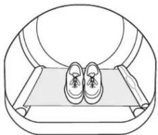
natural_image
Line drawing of a person's feet resting on a treadmill inside a circular frame (no text or symbols)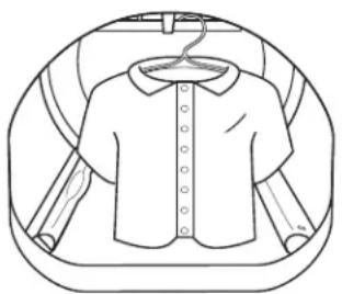
natural_image
Line drawing of a short-sleeve shirt with collar and button details, enclosed in a circular frame (no text or symbols)natural_image
Diagram of a mechanical component inside a circular housing, showing internal components and a rectangular block (no text or symbols)natural_image
Line drawing of a washing machine with a circular component above it (no text or symbols)natural_image
Line drawing of a washing machine with airflow arrows indicating motion (no text or symbols)EMPLACEMENT DE VOTRE SÉCHEUSE
DÉGAGEMENTS MINIMUMS AUTRES QUE POUR UNE INSTALLATION ENCASTRÉE
natural_image
Illustration of two black cables tied at a junction with a coiled cable (no text or symbols)natural_image
Technical line drawing of a mechanical component with a magnified inset showing internal structure (no text or symbols)natural_image
Illustration of a hand connecting pipe fittings to a valve (no text or symbols present)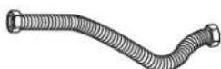
□Tuyau de raccordement
souple
natural_image
Hand placing a component into an electrical box with wires (no text or symbols visible)natural_image
Simple line drawing of a trash bin with a downward arrow and a cigarette inside (no text or symbols)EXIGENCES RELATIVES AU GAZ

AVERTISSEMENT
natural_image
Illustration of a hand holding two threaded fasteners with directional arrows indicating movement (no text or symbols)natural_image
Line drawing of hands using a wrench to adjust a component (no text or symbols present)RACCORDEMENT DE LA SÉCHEUSE À L'ALIMENTATION EN GAZ (SUITE)
natural_image
Illustration of hands connecting a mechanical clamp to a vertical spring (no text or symbols)natural_image
Hand placing a button into an electrical control box (no text or symbols visible)RENSEIGNEMENTS SUR LES RACCORDS ÉLECTRIQUES POUR SÉCHEUSES ÉLECTRIQUES
natural_image
Technical line drawing of a mechanical component or enclosure with no visible text or symbols•COUPEZ
natural_image
Pure technical line drawing of a mechanical assembly without any text, numbers, or symbols•UTILISEZ des
natural_image
Simple line drawing of a prohibition symbol (no text or labels)•N'ÉCRASEZ PAS
natural_image
Diagram of a device with a diagonal line crossing through it, no text or symbols present•N'UTILISEZ PAS une
text_image
Diagram showing a cross-section with a diagonal line and an arrow, indicating a restriction or absence of a device.•N'ÉCRASEZ PAS
natural_image
Simple line drawing of a diagonal line crossing a vertical wall, with no text or symbols present.•N'INSTALLEZ PAS
ÉVACUATION LATÉRALE (suite)
AJOUTER UN COUDE ET UN CONDUIT POUR L'ÉVACUATION SUR LA GAUCHE ET LA DROITE DE L'APPAREIL (suite)
text_image
Plaque (Ensemble WE1M454)ÉVACUATION PAR LE DESSOUS (suite)
natural_image
Technical line drawing of a mechanical assembly inside a transparent enclosure (no text or symbols)text_image
Plaque (Ensemble WE1M454)natural_image
Illustration of a hand holding an electrical outlet with a plug, showing a close-up of the outlet (no text or symbols present)natural_image
Simple line drawing of a curved, elongated object resembling a bent or curved strip (no text or symbols)Poignée externe
natural_image
Simple line drawing of a curved pipe or elbow with two flanged ends and four circular holes (no text or symbols)□Poignée interne
☐A Grandes vis taraudeuses
7 - #10 x 1,125 po
□2
☐B Grandes vis taraudeuses
2 - #10 x 0,75 po
natural_image
Illustration of a plug inserted into an open electrical outlet (no text or symbols)① COMMENT RETIRER LA PORTE
text_image
7 x A Visnatural_image
Pure diagram of a mechanical component with two downward arrows indicating direction (no text or symbols)
text_image
7 x A vis6 COMMENT INVERSER LES CAPUCHONS ET LA GÂCHE DU PANNEAU AVANT
natural_image
Line drawing of a washing machine with control panel and door (no text or symbols)natural_image
Technical line drawing of a rectangular frame with mounting holes and a close-up inset showing internal components (no text or symbols)3 COMMENT INSTALLER LE SUPPORT SUR LA SÉCHEUSE
natural_image
Technical line drawing of a door handle assembly with mounting holes and internal components (no text or symbols)4 COMMENT INSTALLER LA SÉCHEUSE ET LE SUPPORT SUR LA LAVEUSE
natural_image
Top-down line drawing of a vehicle rear compartment showing engine, air gap, and exhaust components (no text or symbols)5 COMMENT TERMINER L'INSTALLATION
natural_image
Technical line drawing of a mechanical device with an inset showing a hand holding a tool (no text or symbols present)POUR LES SÉCHEUSES UNIQUEMENT :
natural_image
Technical line drawing of a mechanical assembly with mounting holes and a circular component (no text or symbols)natural_image
Technical line drawing of a mechanical frame with diagonal braces and mounting holes (no text or symbols)natural_image
Simple line drawing of a mechanical component with a bolt and nut (no text or symbols)natural_image
Technical line drawing of a washing machine with a circular inset showing internal components (no text or symbols)
Garant : General Electric Company. Louisville, KY 40225
Au Canada, contactez : Manager, Consumer Relations, Mabe Canada Inc.
Suite 310, 1 Factory Lane
Moncton, N.B. E1C 9M3
Prolongation de garantie
Aux É.-U.: GEAppliances.com
GE Appliances, Appliance Park
Louisville, KY 40225
Director, Consumer Relations, Mabe Canada Inc.
Suite 310, 1 Factory Lane
Moncton, N.B. E1C 9M3

NSF Protocol P154 Sanitization Performance of Residential Clothes Dryers
natural_image
Diagram of a car's seat and window frame showing the wheel and seat (no text or symbols)Lámpara del tambor
natural_image
Line drawing of a circular mechanical component with two side brackets (no text or symbols)Built-In Rack Dry System (sistema de tendedero incorporado)
natural_image
Diagram of a mechanical component with an inset showing a close-up of a slot or slot (no text or symbols present)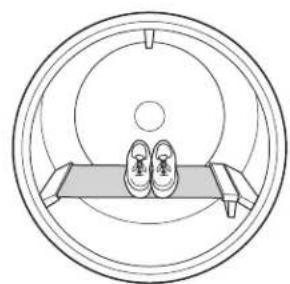
natural_image
Diagram of a circular mechanical or architectural component with two slippers on a base, no text or symbols present.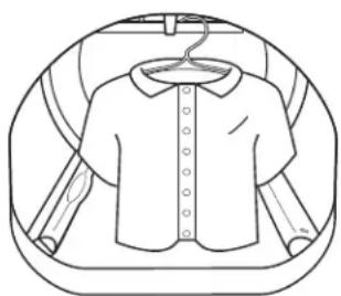
natural_image
Line drawing of a short-sleeve shirt with collar, enclosed in a circular frame (no text or symbols)natural_image
Simple line drawing of a car wheel and dashboard (no text or symbols)natural_image
Line drawing of a computer monitor with an open screen showing internal components (no text or symbols)natural_image
Line drawing of a washing machine with airflow arrows indicating direction (no text or symbols)natural_image
Illustration of two black cables with coiled cable ties (no text or symbols)natural_image
Technical line drawing of a mechanical component with a magnified inset showing internal structure (no text or symbols)natural_image
Illustration of a hand holding a valve with tubing, no text or symbols presentnatural_image
Hand placing a panel into an electrical box with wires (no text or symbols visible)natural_image
Simple line drawing of a trash bin with a downward arrow and a cigarette inside (no text or symbols)natural_image
Illustration of a hand connecting two threaded fasteners to a mechanical component (no text or symbols)natural_image
Line drawing of hands using a tool to adjust or install a flexible hose (no text or symbols present)CÓMO CONECTAR LA SECADORA AL SUMINISTRO DE GAS (cont.)
natural_image
Illustration of hands connecting a mechanical assembly to a vertical spring (no text or symbols)natural_image
Hand placing a button into an electrical control box (no text or symbols visible)natural_image
Technical line drawing of a mechanical component or enclosure with no visible text or symbolsnatural_image
Simple line drawing of a prohibition symbol (no text or labels)natural_image
Simple line drawing of a server unit with a diagonal line crossing it, no text or symbols present.text_image
Diagram showing a crossed-out box with a diagonal line and an arrow indicating leftward direction, enclosed in a circle.natural_image
Simple line drawing of a crossed-out door with diagonal stripe and no text or symbolsnatural_image
Technical line drawing of a mechanical assembly inside a transparent container (no text or symbols)text_image
Elevar Bajar② CONECTE EL CABLE SERIAL
natural_image
Simple line drawing of a curved, elongated object resembling a bent or segmented beam (no text or symbols)□Manija exterior
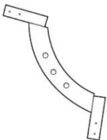
natural_image
Simple line drawing of a curved pipe or elbow with two rectangular ends and four circular holes (no text or symbols)□Manija interior

□2 tapas de la manija
natural_image
Illustration of a plug inserted into an electrical outlet with three socket outlets (no text or symbols)natural_image
Pure diagram of a mechanical component with two downward arrows indicating direction (no text or symbols)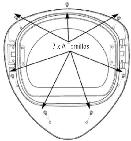
text_image
7 x A Tornillos6 CÓMO INVERTIR LOS BOTONES OBTURADORES DEL PANEL FRONTAL Y LA PLACA DE CERRADO
natural_image
Line drawing of a microwave oven with control panel and vent slots (no text or symbols)natural_image
Technical line drawing of a rectangular electronic device with mounting holes and a close-up inset showing internal components (no text or symbols)3 CÓMO INSTALAR EL SOPORTE EN LA SECADORA
natural_image
Technical line drawing of a door handle and bracket assembly (no text or symbols)4 CÓMO INSTALAR LA SECADORA Y EL SOPORTE EN LA LAVADORA
natural_image
Diagram of a rear panel with labeled components including a coiled cable, socket, and power plug (no text or symbols present)natural_image
Technical line drawing of a mechanical component with an inset showing a hand using a tool to adjust or install a part (no text or symbols present)SÓLO PARA SECADORAS:
natural_image
Technical line drawing of a mechanical assembly with mounting holes and a circular inset showing internal components (no text or symbols)natural_image
Technical line drawing of a mechanical frame with diagonal braces and mounting holes (no text or symbols)natural_image
Technical line drawing of a mechanical component with a bolt and nut (no text or symbols)6 QUITE LOS TORNILLOS DE EMPAQUE
Garante: General Electric Company. Louisville, KY 40225

Have a question or need assistance with your appliance? Try the GE Appliances Website 24 hours a day, any day of the year! For greater convenience and faster service, you can now download Owner's Manuals, order parts or even schedule service on-line. In Canada: www.GEAppliances.ca
Schedule Service
In the U.S.: GEAppliances.com
Expert GE repair service is only one step away from your door. Get on-line and schedule your service at your convenience any day of the year! Or call 800.GE.CARES (800.432.2737) during normal business hours. In Canada, call 1.800.561.3344
Real Life Design Studio
In the U.S.: GEAppliances.com
GE supports the Universal Design concept—products, services and environments that can be used by people of all ages, sizes and capabilities. We recognize the need to design for a wide range of physical and mental abilities and impairments. For details of GE's Universal Design applications, including kitchen design ideas for people with disabilities, check out our Website today. For the hearing impaired, please call 800.TDD.GEAC (800.833.4322).
In Canada, contact: Manager, Consumer Relations, Mabe Canada Inc.
Suite 310, 1 Factory Lane
Moncton, N.B. E1C 9M3
Extended Warranties
In the U.S.: GEAppliances.com
Purchase a GE extended warranty and learn about special discounts that are available while your warranty is still in effect. You can purchase it on-line anytime, or call 800.626.2224 during normal business hours. GE Consumer Home Services will still be there after your warranty expires. In Canada, call 1.888.261.2133
Parts and Accessories
In the U.S.: GEAppliances.com
Individuals qualified to service their own appliances can have parts or accessories sent directly to their homes (VISA, MasterCard and Discover cards are accepted). Order on-line today, 24 hours every day or by phone at 800.626.2002 during normal business hours.
Instructions contained in this manual cover procedures to be performed by any user. Other servicing generally should be referred to qualified service personnel. Caution must be exercised, since improper servicing may cause unsafe operation.
Customers in Canada should consult the yellow pages for the nearest Mabe service center, or call 1.800.661.1616.

Contact Us
In the U.S.: GEAppliances.com
If you are not satisfied with the service you receive from GE, contact us on our Website with all the details including your phone number, or write to: General Manager, Customer Relations
GE Appliances, Appliance Park
Louisville, KY 40225
In Canada: www.GEAppliances.ca, or write to:
Director, Consumer Relations, Mabe Canada Inc.
Suite 310, 1 Factory Lane
Moncton, N.B. E1C 9M3
Register Your Appliance
In the U.S.: GEAppliances.com
Register your new appliance on-line—at your convenience! Timely product registration will allow for enhanced communication and prompt service under the terms of your warranty, should the need arise. You may also mail in the pre-printed registration card included in the packing material. In Canada: www.GEAppliances.ca