DG10C45BE - Sink Concept - Free user manual and instructions
Find the device manual for free DG10C45BE Concept in PDF.

User questions about DG10C45BE Concept
0 question about this device. Answer the ones you know or ask your own.
Ask a new question about this device
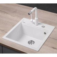
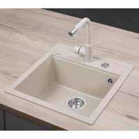
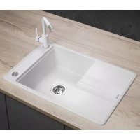
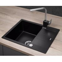
Download the instructions for your Sink in PDF format for free! Find your manual DG10C45BE - Concept and take your electronic device back in hand. On this page are published all the documents necessary for the use of your device. DG10C45BE by Concept.
USER MANUAL DG10C45BE Concept
natural_image
Line drawing of a safe with a circular dial and horizontal panel, no text or symbols presentZlew kuchenny / Kitchen sink /
natural_image
Illustration of a coffee cup and pencil on a desk with a dashed line indicating writing or drawing (no text or symbols present)2.
natural_image
Silhouette of a drill bit with a screw, shown in a technical diagram without any text or symbols.3.
natural_image
Illustration of a hand tool cutting through a curved ramp, with dashed lines indicating motion (no text or symbols)
natural_image
Abstract illustration of a paintbrush touching a flat surface (no text or symbols)4.
natural_image
Diagram showing a container being lowered into a sink, with a downward arrow indicating the process (no text or symbols present)5.
natural_image
Diagram showing a tool interacting with a pipe and screwdriver, no text or symbols present7.
CZ
ZÁRUKA
natural_image
Illustration of a coffee cup and pencil on a desk with a dashed line indicating writing or drawing (no text or symbols present)2.
natural_image
Silhouette of a drill bit with a screw, shown in a technical diagram without any text or symbols.3.
natural_image
Illustration of a hand tool cutting through a curved ramp, with dashed lines indicating motion (no text or symbols)
natural_image
Abstract illustration of a paintbrush touching a screen (no text or symbols)4.
Po okrajoch otvoru aplikujte sanitárny silikón.
natural_image
Simple line drawing of a rectangular basin with a downward arrow indicating flow or movement (no text or symbols)5.
natural_image
Diagram of a mechanical clamp or clamping device with no visible text or symbols7.
ZÁRUKA
natural_image
Illustration of a coffee cup and pencil on a desk with a dashed line indicating writing or drawing (no text or symbols present)2.
natural_image
Silhouette of a drill bit with a screw, shown in a technical diagram without any text or symbols.3.
natural_image
Illustration of a hand tool cutting through a curved ramp, with dashed lines indicating motion (no text or symbols)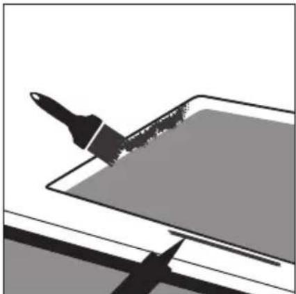
natural_image
Abstract illustration of a paintbrush touching a screen (no text or symbols)4.
natural_image
Simple line drawing of a container with an arrow pointing downward into a rectangular basin (no text or symbols)5.
natural_image
Diagram of a mechanical assembly with a tool, screwdriver, and pipe connection (no text or symbols)7.
PL
GWARANCJA
Thank you for purchasing a Concept product. We wish you much joy with your new appliance every day you use it. Please read the instruction manual carefully before initial use. To refer to this manual any time you need to, we recommend you to keep it in a safe place. And please pass it to any future owner of the appliance. Follow the recommendations in the manual and then use the new product successfully.
TABLE OF CONTENTS
- Important safety information
- Cleaning and maintenance
- Sink installation
• Installation of drain pipes - Warranty
CLEANING AND MAINTENANCE
Concept granite sinks contain more than 80 % crushed stone and 15-20 % binder. Thanks to this technology, they are very strong and can withstand external pressure. The sink surface is non-porous and smooth which greatly facilitates cleaning and maintenance.
After each use, clean the sink with water and non-abrasive liquid cleaners. After cleaning, rinse the sink surface with water and dry. Remove larger dirt and debris with vinegar solution, or with detergent containing vinegar. After use, dry the sink surface with a soft cloth. Regular drying protects the sink from unwanted scale deposits.
From time to time, wash the product with low concentration non-abrasive milk suitable for granite sinks. Rinse the surface with warm water and dry with a soft cloth.
Although the granite surface of sinks is durable and well protected against external influences, daily and regular care of the sink prolongs its life.
IMPORTANT SAFETY INFORMATION
Although the surface of the sink is heat resistant up to 280 °C, remember that the cookware may be heated to higher temperatures. In addition, if hot dishes are placed on a wet surface, the risk of irreversible damage to the exterior of the sink increases. We recommend placing hot dishes on the mats intended for this purpose.
Do not throw pots, pans or sharp metal products into the sink.
Do not leave aggressive foods such as salt, vinegar, mustard, red wine and black tea on the surface of the sink for extended periods of time. Immediately after pouring into the sink, rinse it with warm water.
EN
SINK INSTALLATION
Please follow the following instruction during product installation: The warranty does not cover damages caused by incorrect installation.
These instructions are for installation of sinks that are placed on the kitchen counter top only.
Before product installation, make sure it is not damaged in any way.
The product should be installed by a qualified professional.
1.
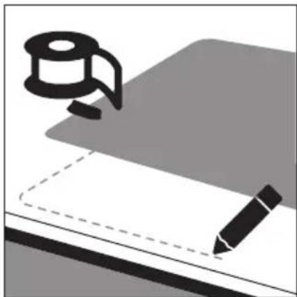
Select a location suitable for the sink. The worktop surface must be horizontal and have sufficient space under it. Place the template, which is always included in the package, and fix it with adhesive tape. Then trace the template with a pencil.

natural_image
Illustration of a coffee cup and pencil on a desk with a dashed line indicating writing or drawing (no text or symbols present)2.
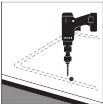
In each corner, drill a hole of 10 mm.

natural_image
Silhouette of a drill bit with a screw, shown in a technical diagram without any text or symbols.3.
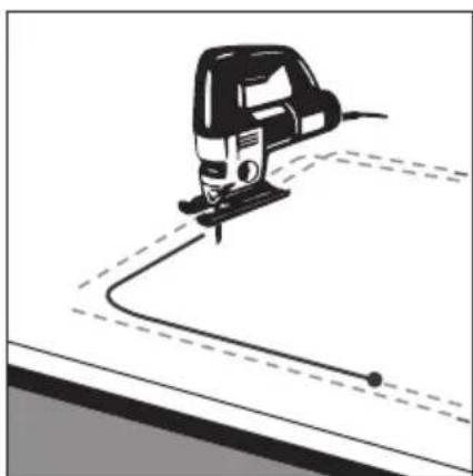
Using a reciprocating saw, cut the sink hole.

natural_image
Illustration of a hand tool cutting through a curved ramp, with dashed lines indicating motion (no text or symbols)
natural_image
Abstract illustration of a paintbrush touching a screen (no text or symbols)4.
Apply sanitary silicone along the edge of the hole.
natural_image
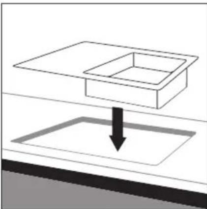
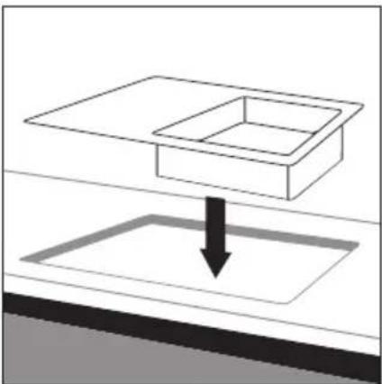
Simple line drawing of a rectangular basin with a downward arrow indicating flow or movement (no text or symbols)5.
Place the sink in the hole. Check that the sink is positioned correctly.
6.
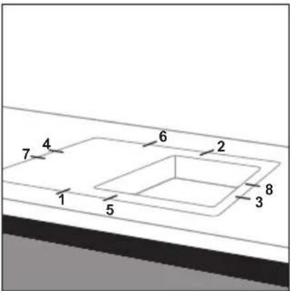
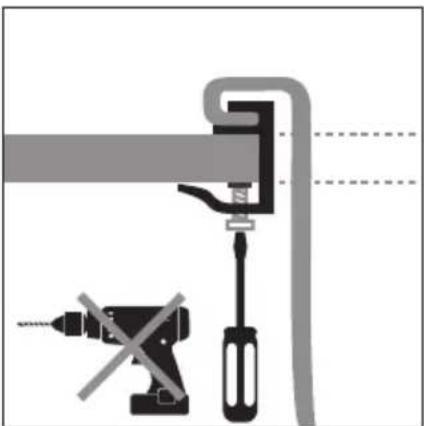
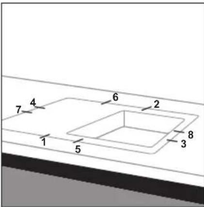
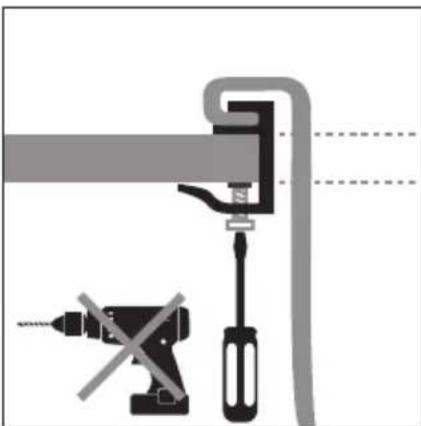
Place the enclosed sink holders in the order shown on the diagram and tighten them as close as possible to the surface of the kitchen counter top.
natural_image
Diagram showing a pipe clamp securing a screwdriver and a tool, with no visible text or symbols7.
Tighten only manually so the sink is firmly anchored. Do not use electric drills or other devices without a torque regulator. Carefully remove any excess silicone from the surface of the counter top and sink.
EN
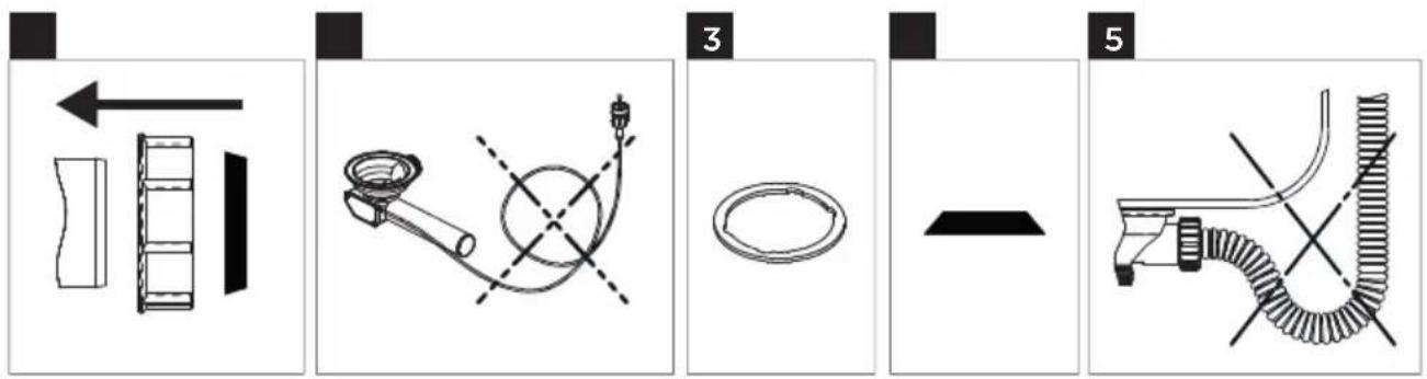
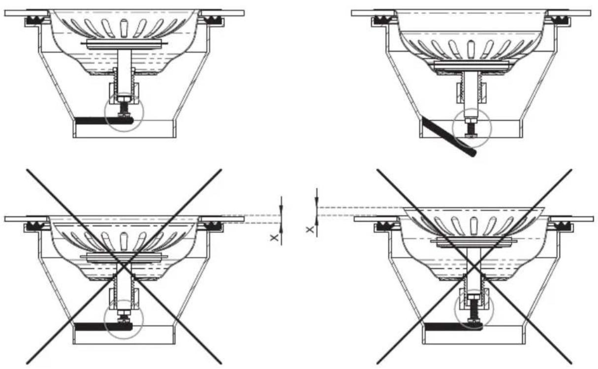
INSTALLATION OF DRAIN PIPES
Detailed drawing of all parts of the drain pipe.
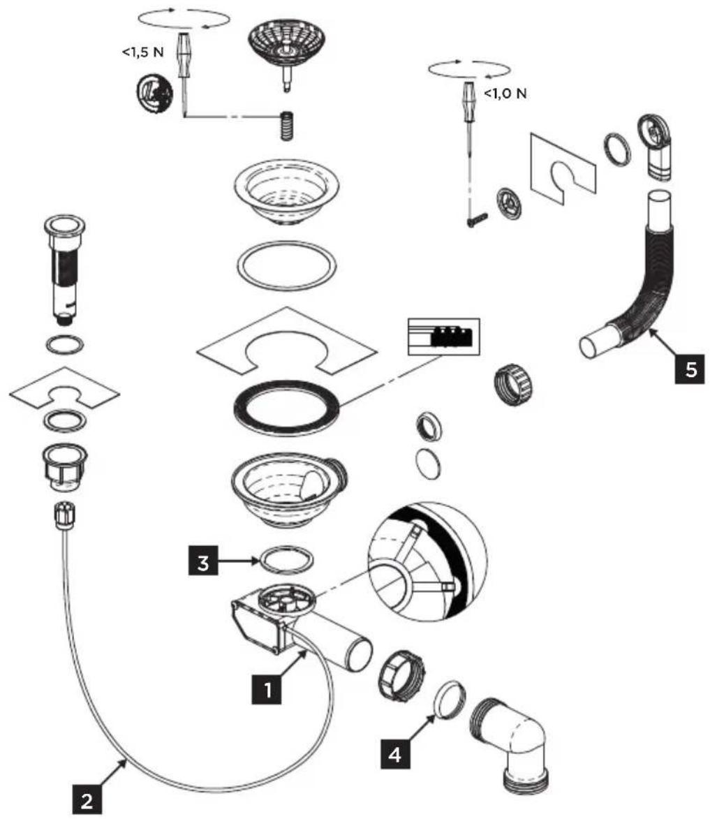

The package contains two types of gasket.
Gasket A - 1 mm, sink upper installation and gasket B - 2 mm, sink lower installation.
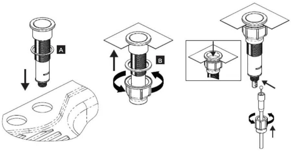
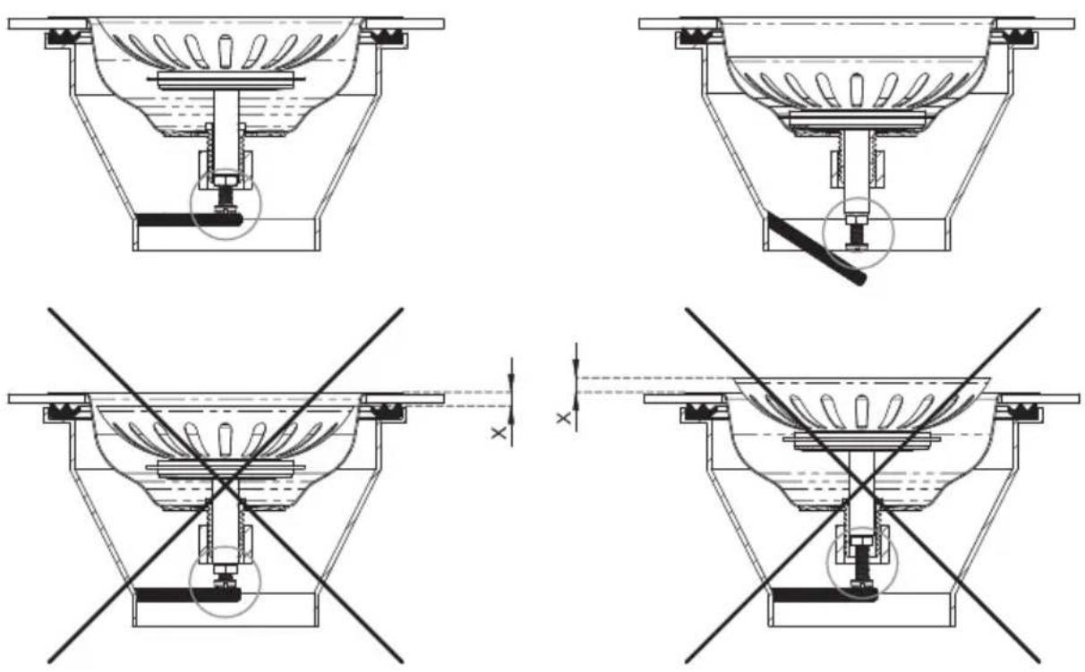
Adjust the stainless steel drain to the optimum position by the screw.
EN
WARRANTY
The manufacturer is responsible for manufacturing and material defects during the warranty period specified by the manufacturer. In the event that such defects occur, please return the sink to the seller with enclosed documents of its acquisition. Keep these documents throughout the warranty period.
The warranty does not cover defects caused by incorrect assembly or maintenance. Damages from failure to follow the manufacturer's instructions are not covered by the warranty.
ACKNOWLEDGMENT
Thank you for purchasing a Concept product. We wish you much joy with your new appliance every day you use it. Please read the instruction manual carefully before initial use. To refer to this manual any time you need to, we recommend you to keep it in a safe place. And please pass it to any future owner of the appliance. Follow the recommendations in the manual and then use the new product successfully.
TABLE OF CONTENTS
- Important safety information
- Cleaning and maintenance
- Sink installation
• Installation of drain pipes - Warranty
CLEANING AND MAINTENANCE
Concept granite sinks contain more than 80 % crushed stone and 15-20 % binder. Thanks to this technology, they are very strong and can withstand external pressure. The sink surface is non-porous and smooth which greatly facilitates cleaning and maintenance.
After each use, clean the sink with water and non-abrasive liquid cleaners. After cleaning, rinse the sink surface with water and dry. Remove larger dirt and debris with vinegar solution, or with detergent containing vinegar. After use, dry the sink surface with a soft cloth. Regular drying protects the sink from unwanted scale deposits.
From time to time, wash the product with low concentration non-abrasive milk suitable for granite sinks. Rinse the surface with warm water and dry with a soft cloth.
Although the granite surface of sinks is durable and well protected against external influences, daily and regular care of the sink prolongs its life.
IMPORTANT SAFETY INFORMATION
Although the surface of the sink is heat resistant up to 280 °C, remember that the cookware may be heated to higher temperatures. In addition, if hot dishes are placed on a wet surface, the risk of irreversible damage to the exterior of the sink increases. We recommend placing hot dishes on the mats intended for this purpose.
Do not throw pots, pans or sharp metal products into the sink.
Do not leave aggressive foods such as salt, vinegar, mustard, red wine and black tea on the surface of the sink for extended periods of time. Immediately after pouring into the sink, rinse it with warm water.
HU
SINK INSTALLATION
Please follow the following instruction during product installation: The warranty does not cover damages caused by incorrect installation.
These instructions are for installation of sinks that are placed on the kitchen counter top only.
Before product installation, make sure it is not damaged in any way.
The product should be installed by a qualified professional.
1.
Select a location suitable for the sink. The worktop surface must be horizontal and have sufficient space under it. Place the template, which is always included in the package, and fix it with adhesive tape. Then trace the template with a pencil.
natural_image
Illustration of a coffee cup and pencil on a desk with a dashed line indicating writing or drawing (no text or symbols present)2.
In each corner, drill a hole of 10 mm.
natural_image
Silhouette of a drill bit with a screw, shown in a technical diagram without any text or symbols.3.
Using a reciprocating saw, cut the sink hole.
natural_image
Illustration of a hand tool cutting through a curved ramp, with dashed lines indicating motion (no text or symbols)
natural_image
Abstract illustration of a paintbrush touching a screen (no text or symbols)4.
Apply sanitary silicone along the edge of the hole.

natural_image
Simple line drawing of a rectangular basin with a downward arrow indicating flow or movement (no text or symbols)5.
Place the sink in the hole. Check that the sink is positioned correctly.
6.
Place the enclosed sink holders in the order shown on the diagram and tighten them as close as possible to the surface of the kitchen counter top.
natural_image
Diagram of a mechanical clamp or clamping device with no visible text or symbols7.
Tighten only manually so the sink is firmly anchored. Do not use electric drills or other devices without a torque regulator. Carefully remove any excess silicone from the surface of the counter top and sink.
INSTALLATION OF DRAIN PIPES
Detailed drawing of all parts of the drain pipe.

The package contains two types of gasket.
Gasket A - 1 mm, sink upper installation and gasket B - 2 mm, sink lower installation.

Adjust the stainless steel drain to the optimum position by the screw.
WARRANTY
The manufacturer is responsible for manufacturing and material defects during the warranty period specified by the manufacturer. In the event that such defects occur, please return the sink to the seller with enclosed documents of its acquisition. Keep these documents throughout the warranty period.
The warranty does not cover defects caused by incorrect assembly or maintenance. Damages from failure to follow the manufacturer's instructions are not covered by the warranty.
DANKSAGUNG
natural_image
Illustration of a pen writing on a notepad with a spool of paper nearby (no text or symbols)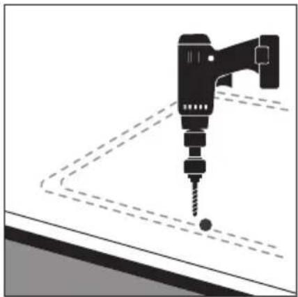
natural_image
Silhouette of a drill bit with a screw, shown against a plain background (no text or symbols)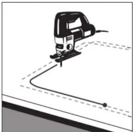
natural_image
Illustration of a hand tool cutting through a curved path with dashed lines (no text or symbols)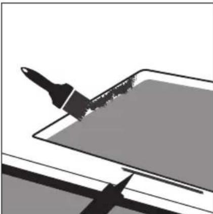
natural_image
Abstract illustration of a paintbrush touching a screen (no text or symbols)4.
natural_image
Simple line drawing of a rectangular basin with a downward arrow indicating flow or movement (no text or symbols)5.
natural_image
Diagram of a mechanical clamp or tool assembly with no visible text or symbols7.
GARANTIE
natural_image
Illustration of a coffee cup and pencil on a desk with a dashed line indicating writing or drawing (no text or symbols present)2.
natural_image
Silhouette of a drill bit with a screw, shown in a technical diagram without any text or symbols.3.
natural_image
Illustration of a hand tool cutting through a curved ramp, with dashed lines indicating motion (no text or symbols)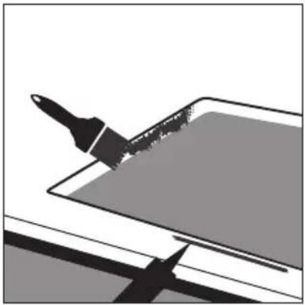
natural_image
Abstract illustration of a paintbrush touching a surface with a brush tip, no text or symbols present.4.
natural_image
Diagram showing a container being lowered into a sink, with a downward arrow indicating the process (no text or symbols present)5.
natural_image
Diagram showing a tool and screwdriver assembly with no visible text or symbols7.
GARANTÍA
natural_image
Illustration of a coffee cup and pencil on a notepad, no text or symbols present2.
natural_image
Silhouette of a drill bit with a screw and base, shown in black and white (no text or symbols)3.
natural_image
Illustration of a hand tool cutting through a curved path with dashed lines (no text or symbols)
natural_image
Abstract illustration of a paintbrush touching a screen (no text or symbols)4.
natural_image
Simple line drawing of a rectangular basin with a downward arrow indicating flow or movement (no text or symbols)5.
natural_image
Diagram of a mechanical clamp or clamping device with no visible text or symbols7.
IT
GARANZIA
natural_image
Illustration of a coffee cup and pencil on a desk with a dashed line indicating writing or drawing (no text or symbols present)2.
natural_image
Silhouette of a drill bit with a screw, shown in a technical diagram without any text or symbols.3.
natural_image
Illustration of a hand tool cutting through a curved ramp, with dashed lines indicating motion (no text or symbols)
natural_image
Abstract illustration of a paintbrush touching a screen (no text or symbols)4.
natural_image
Simple line drawing of a rectangular basin with a downward arrow indicating flow or movement (no text or symbols)5.
natural_image
Diagram of a mechanical clamp or tool assembly with no visible text or symbols7.
FR
GARANTIE
W: www.my-concept.pl

Jindřich Valenta—Concept
Vysokomýtská 1800,
565 01 Choceň, Czech Republic
T: +420 465 471 400
E: info@my-concept.cz
W: www.my-concept.cz