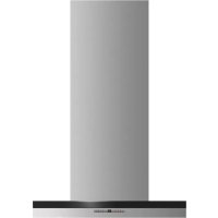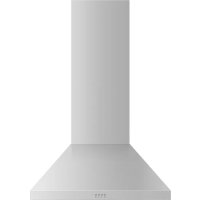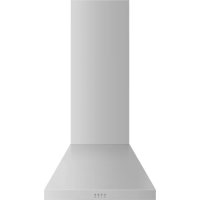
HC24PCX1 - Fan Fisher & Paykel - Free user manual and instructions
Find the device manual for free HC24PCX1 Fisher & Paykel in PDF.


User questions about HC24PCX1 Fisher & Paykel
0 question about this device. Answer the ones you know or ask your own.
Ask a new question about this device
Download the instructions for your Fan in PDF format for free! Find your manual HC24PCX1 - Fisher & Paykel and take your electronic device back in hand. On this page are published all the documents necessary for the use of your device. HC24PCX1 by Fisher & Paykel.
USER MANUAL HC24PCX1 Fisher & Paykel
HC36PCB1, HC36PCR1 & HC36PCW1
USER GUIDE
US CA
Safety and warnings 5
Control panel 8
Care and cleaning 9
Parts and accessories 12
Warranty and service 13
Registration
To register your product visit our website: fisherpaykel.com/register
WARNING!

Electric Shock Hazard
Failure to follow this advice may result in electric shock or death.
- Always disconnect the appliance from the mains power supply before carrying out any maintenance or repairs. Failure to do so can result in death, electric shock, fire or injury to persons.
- Do not immerse cord or plugs in water or other liquid.
! WARNING!
Weight Hazard
Failure to follow this advice may result in personal injury
- The appliance is heavy. Please ensure adequate care is taken when installing the appliance to prevent personal injury. The appliance must be installed onto a solid wall, stud, beam or truss.
- Product weight: HC24 42 lb (19 kg), HC30 35 lb (21.5 kg), HC36 37 lb (23.8 kg).
READ AND SAVE THESE INSTRUCTIONS
WARNING!
When using this appliance always exercise basic safety precautions including the following:
General
- CAUTION: FOR GENERAL VENTILATING USE ONLY. DO NOT USE TO EXHAUST HAZARDOUS OR EXPLOSIVE MATERIALS AND VAPORS.
- This appliance is not intended for use by persons (including children) with reduced physical, sensory or mental capabilities, or lack of experience and knowledge, unless they have been given supervision or instruction concerning the use of the appliance by a person responsible for their safety.
- Children should be supervised to ensure they do not play with the appliance. Cleaning and user maintenance shall not be made by children without supervision.
- Never use the range hood without the filters in place.
- CAUTION: accessible parts may become hot when used with cooking appliances.
- Remove all packaging, including protective wrappings, before use.
- The range hood may stop working during an electrostatic discharge (eg lightning). Switch off the electricity supply to the range hood and reconnect after one minute.
Cleaning
• There is a fire risk if cleaning is not carried out in accordance with the instructions.
- Unplug or disconnect the appliance from the power supply before servicing or cleaning.
- Never use abrasive or oil based cleaners.
- Wear gloves to protect against sharp edges.
- When replacing the bulb, let the bulb cool, and ensure that power to the range hood has been turned off.
- Use new bulbs according to that indicated on the range hood nameplate.
Fire
WARNING! TO REDUCE THE RISK OF FIRE, ELECTRIC SHOCK, OR INJURY TO PERSONS, OBSERVE THE FOLLOWING:
- Installation work and electrical wiring must be done by qualified person(s) in accordance with all applicable codes and standards, including fire-rated construction.
- Sufficient air is needed for proper combustion and exhausting of gases through the flue (chimney) of fuel burning equipment to prevent back drafting. Follow the heating equipment manufacturer's guideline and safety standards such as those published by the National Fire Protection Association (NFPA), and the American Society for Heating, Refrigeration and Air Conditioning Engineers (ASHRAE), and the local code authorities.
- When cutting or drilling into wall or ceiling, do not damage electrical wiring and other hidden utilities.
- Ducted fans must always be vented to the outdoors.
- Use this unit only in the manner intended by the manufacturer. If you have questions, contact the manufacturer. For residential use only.
- Before servicing or cleaning unit, switch power off at service panel and lock the service disconnecting means to prevent power from being switched on accidentally. When the service disconnecting means cannot be locked, securely fasten a prominent warning device, such as a tag, to the service panel.
• This unit must be grounded. - Never leave frying food unattended since grease can overheat and catch fire. The risk of fire is even greater in the case of used oil.
- Do not use replacement parts that have not been recommended by the manufacturer (e.g. parts made at home using a 3D printer).
WARNING: TO REDUCE THE RISK OF INJURY TO PERSONS IN THE EVENT OF A RANGE TOP GREASE FIRE, OBSERVE THE FOLLOWING*:
- SMOTHER FLAMES with a close-fitting lid, cookie sheet, or metal tray, then turn off the burner. BE CAREFUL TO PREVENT BURNS. If the flames do not go out immediately, EVACUATE AND CALL THE FIRE DEPARTMENT.
- NEVER PICK UP A FLAMING PAN - You may be burned.
- DO NOT USE WATER, including wet dishcloths or towels – a violent steam explosion will result.
-
Use an extinguisher ONLY if:
-
You know you have a Class ABC extinguisher, and you already know how to operate it.
- The fire is small and contained in the area where it started.
• The fire department is being called. - You can fight the fire with your back to an exit.
- When product is used in recirculation mode, use only conversion kit number 792162 Recirculation diverter and 792163 Recirculation carbon filter.
WARNING: TO REDUCE THE RISK OF A RANGE TOP GREASE FIRE:
- Never leave surface units unattended at high settings. Boilovers cause smoking and greasy spillovers that may ignite. Heat oils slowly on low or medium settings.
• Always turn hood ON when cooking at high heat or when flambéing food (ie Crepes Suzette, Cherries Jubilee, Peppercorn Beef Flambé) - Clean ventilating fans frequently. Grease should not be allowed to accumulate on fan or filter.
- Use proper pan size. Always use cookware appropriate for the size of the surface element.
Control panel
text_image
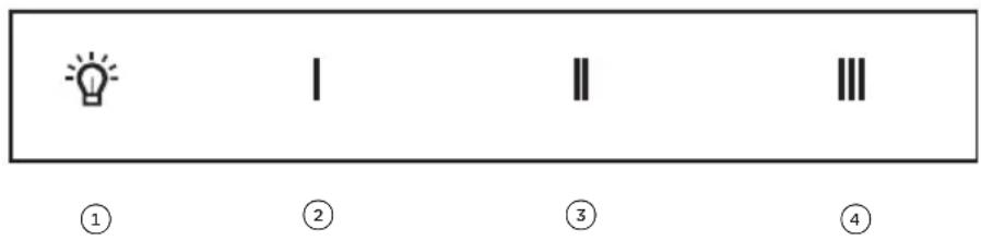
① ② ③ ④CONTROL PANEL FEATURES
① Light
② Fan speed 1
③ Fan speed 2
④ Fan speed 3
This range hood should be cleaned regularly using a mild, liquid detergent and a clean soft cloth to avoid a build-up of grease occurring. Avoid the use of corrosive chemicals, abrasive cleaning products, hard brushes and steel wool pads. Grease deposits are corrosive which can cause damage.
In areas of high humidity or coastal environments, cleaning should be carried out more frequently. Disconnect the product from the power source before undergoing any cleaning.
Do not operate the hood without filters in place.
Aluminum filters
- Clean the filters at least once a month. Filters may need to be cleaned more frequently depending on the cooking methods used and frequency of use.
- Aluminum filters should be removed and cleaned with hot soapy water or in a dishwasher.
- If washed in a dishwasher, the filter should be placed in an upright position to prevent food from falling on them.
• After rinsing and drying, refit the filters.
Carbon filters - for use in recirculation mode
Active carbon filters are disposable items designed to remove grease and odors from cooking vapors before the air is channeled back into the kitchen. The active carbon filters must be replaced periodically to work properly, at least once every six months, depending on the frequency with which the ventilation hood is used.
Fully saturated carbon filters can become a barrier to air movement therefore limiting ventilation hood performance. In the event of fire, grease laden filters could be flammable and therefore regular replacement is recommended.
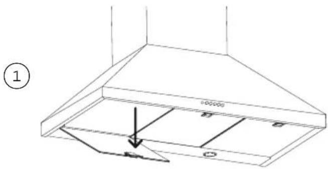
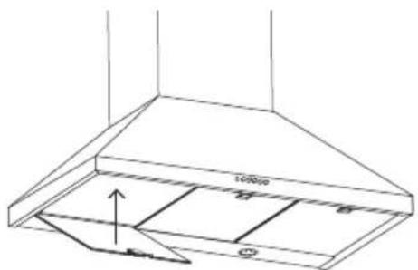
Removing the aluminium filters
text_image
①Pull the catch and tilt the filter downwards until it disengages from the supports.
Replacing the aluminium filters
natural_image
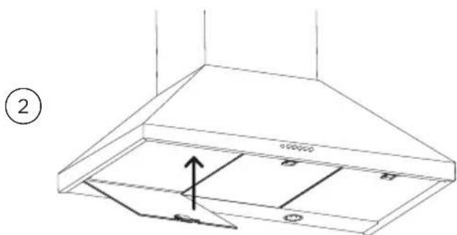
Technical line drawing of a ceiling structure with ventilation duct and mounting points (no text or symbols)Place the filter into the support at the rear of the range hood. Push the filter back into place.
Replacing the light bulb
①
natural_image
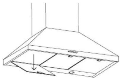
Technical line drawing of a ceiling structure with ventilation duct and mounting brackets (no text or symbols)Remove the aluminum filters.
②
natural_image
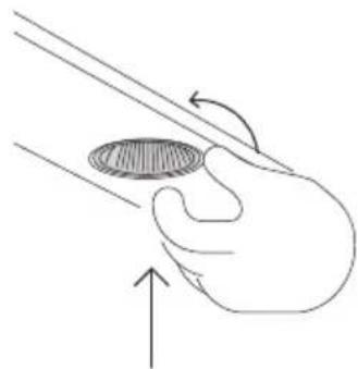
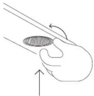
Illustration of a hand holding a circular object with an arrow indicating rotation (no text or symbols)Lightly push the light bulb up and rotate anti-clockwise to remove.
③
natural_image
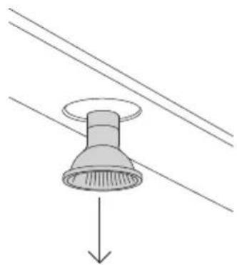
Simple line drawing of a ceiling lamp with a down arrow, no text or symbols presentReplace light bulb with a light bulb no more powerful.
Refer to range hood rating plate for detail.
④
natural_image
Technical line drawing of a ceiling structure with ventilation duct and mounting bracket (no text or symbols)Refit the aluminum filters.
| ITEM REFERENCE NUMBER | |
| LED bulb 792579 | |
| Recirculation carbon filter 793162 | |
| Recirculation diverter 793163 | |
| OPTIONAL ACCESSORIES REFERENCE NUMBER | |
| Coverduct extension black 793223 | |
| Coverduct extension white 793224 | |
| Coverduct extension red 793225 | |
| Coverduct stainless 791774 |
Before you call for service or assistance
Check the things you can do yourself. Refer to the installation guide and user guide and check that:
- Your product is correctly installed.
- You are familiar with its normal operation.
If after checking these points you still need assistance or parts, please refer to the Service & Warranty book for warranty details and your nearest Service Center, Customer Care, or contact us through our website www.fisherpaykel.com
Complete and keep for safe reference:
Model
Serial No.
Purchase Date
Purchaser
Dealer
City
State
Zip
Country
FISHER & PAYKEL
WALL RANGE HOOD, CHIMNEY PYRAMID
CLASSIC
HC24PCX1, HC30PCX1, HC30PCB1, HC30PCR1, HC30PCW1, HC36PCX1,
HC36PCB1, HC36PCR1 & HC36PCW1
INSTALLATION GUIDE
US CA
Safety and warnings 4
Components list 6
Prior to installation 7
Product dimensions-24" models 8
Product dimensions - 30" models 10
Product dimensions - 36" models 12
Installation height 14
Attachment dimensions 15
Venting options 16
Recirculation installation 17
Chimney extension 18
Electrical requirements 19
Prepare range hood 20
Attach brackets and mounting screws 21
Hang range hood 22
Electrical connection 23
Attach chimney 24
Final checklist 25
Registration
To register your product visit our website: fisherpaykel.com/register
WARNING!
Electric Shock Hazard
Failure to follow this advice may result in electric shock or death.
- Installation work and electrical wiring must be done by qualified person(s) in accordance with all applicable codes and standards, including fire-rated construction.
- To reduce the risk of fire or electric shock, do not use this fan with any solid-state speed control device.
WARNING!
Weight Hazard
Failure to follow this advice may result in personal injury
- The appliance is heavy. Please ensure adequate care is taken when installing the appliance to prevent personal injury. The appliance must be installed onto a solid wall, stud, beam or truss.
- Product weight: HC24 42 lb (19 kg), HC30 35 lb (21.5 kg), HC36 37 lb (23.8 kg).
READ AND SAVE THESE INSTRUCTIONS
WARNING!
When using this appliance always exercise basic safety precautions including the following:
General
- Please read the entire set of instructions before installing or using this appliance.
- Please make this information available to the person installing the appliance.
• Always switch the power off prior to installation, servicing or cleaning of the appliance. - The room must have adequate ventilation when the range hood is used at the same time as appliances burning gas or other fuels.
- Stainless steel or powdercoat is very easily damaged during installation if abraded or knocked by tools. It is recommended to protect the top of the appliance with cardboard or polystyrene during the installation to minimise the risk of damage occurring.
- To reduce the risk of damage occurring to the cooktop, it is recommended that the surface of the cooktop is protected with cardboard or a similar object during installation of the range hood.
- Attention should be given to ensure that any applicable regulations concerning the discharge of exhaust air are fulfilled.
- Before connecting any pipes, consult municipal ordinances to ensure that any applicable regulations concerning the discharge of exhaust air are adhered to and request permission from the person in charge of the building.
- Exhaust air must not be discharged into an existing flue that is used for exhausting fumes from appliances burning gas or other fuels.
WARNING! TO REDUCE THE RISK OF FIRE, ELECTRIC SHOCK, OR INJURY TO PERSONS, OBSERVE THE FOLLOWING:
- Installation work and electrical wiring must be done by qualified person(s) in accordance with all applicable codes and standards, including fire-rated construction.
- Sufficient air is needed for proper combustion and exhausting of gases through the flue (chimney) of fuel burning equipment to prevent back drafting.
Follow the heating equipment manufacturer's guideline and safety standards such as those published by the National Fire Protection Association (NFPA), and the American Society for Heating, Refrigeration and Air Conditioning Engineers (ASHRAE), and the local code authorities.
- When cutting or drilling into wall or ceiling, do not damage electrical wiring and other hidden utilities.
- Ducted fans must always be vented to the outdoors.
• This unit must be grounded. - Wear gloves to protect against sharp edges.
Electrical
- This appliance must be installed and connected to the mains power supply only by a qualified person according to these installation instructions and in compliance with any applicable local building and electricity regulations. Failure to install the appliance correctly could invalidate any warranty or liability claims.
- To comply with electrical safety regulations, the appliance must be plugged into a socket near the appliance. The socket must be accessible, or have an accessible isolating switch, to enable the end user to isolate the appliance from the power for the purpose of internal cleaning or maintenance.
- A power outlet should be within 750mm of the motor assembly and can either be on the wall, behind the chimney or in the ceiling.
- If the supply cord of this equipment is damaged, it must only be replaced by the manufacturer, its service agent or similarly qualified person in order to avoid a hazard.
- Ducting accessories are not supplied. All ducting must comply with local requirements and building codes.
- Electrical wiring must be done by qualified person(s) in accordance with all applicable codes and standards and the unit must be grounded.
• Installation work and electrical wiring must be done by qualified person(s) in accordance with all applicable codes and standards, including fire-rated construction.
Fire
- WARNING: To reduce the risk of fire, use only metal ductwork. Do not use flexible plastic ducting.
- CAUTION: To reduce risk of fire and to properly exhaust air, be sure to duct air outside – do not vent exhaust air into spaces within walls or ceilings or into attics, crawl spaces, or garages.
- To reduce the risk of fire and electric shock, install this range hood only with the integral blowers supplied with this range hood.
- The 8' metal duct adapter supplied with this rangehood must be used for connecting any ducting to this rangehood. Ducting should not be fitted onto the plastic blower outlet.
natural_image
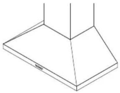
Isometric line drawing of a metal frame with no text or symbolsRange hood (1)
text_image
FISHER & PAYCEL WALL RANGE HOODO, CHIPM&T PYRANID —— 1997 BEEFRED HOSPITAL CABBAGE & CHEESE & CHEESE & CHEESE 2004 BEEFRED HOSPITAL CABBAGE & CHEESE & CHEESE & CHEESE 2014Installation guide (1)

natural_image
Simple line drawing of a 3D rectangular box with a vertical line inside (no text or symbols)Chimney (1)
natural_image
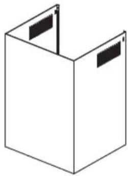
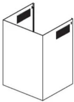
Simple line drawing of a 3D box with two side panels (no text or symbols)Upper chimney (1)
natural_image
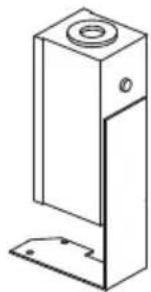
Technical line drawing of a vertical rectangular device with a circular top and mounting base (no text or symbols)Power connection box (1)
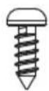
3/8" (10 mm)
Self tapping
screw (4)
natural_image
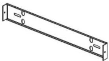
Isometric line drawing of a rectangular metal beam with two circular cutouts (no text or symbols)Upper chimney bracket (1)
natural_image
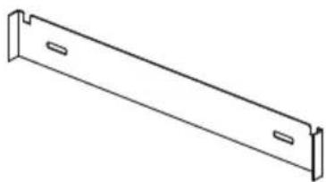
Simple line drawing of a metal bracket with two notches (no text or symbols)Chimney bracket (1)
1 3/16" (30 mm)
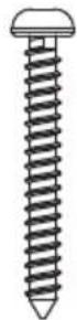
Self tapping screw (10)
1 3/16" (30 mm)
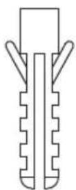
Expansion plug (10)
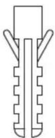
1 3/4"(44 mm)
Drywall expansion plug (8)
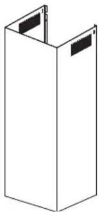
natural_image
Simple line drawing of a rectangular box with two side tabs (no text or symbols)Coverduct extension
Optional accessory- not included with the appliance and must be purchased separately
The manufacturer is not liable for any damage caused by not following these instructions.
- Unpack the range hood.
- Ensure the voltage (V) and the frequency (Hz) indicated on the rating plate match the voltage and frequency of the installation site.
- Check that the area behind the installation surface to be drilled is clear of any electrical cables or pipes etc.
- The range hood surfaces can be damaged during installation if grazed or knocked by tools. Please take care to protect the surfaces during installation.
- Protect the cooktop surface with cardboard, or the like, to prevent damage occurring whilst the range hood is being installed above.
- The wall used for mounting the range hood should have sufficient strength and a flat surface.
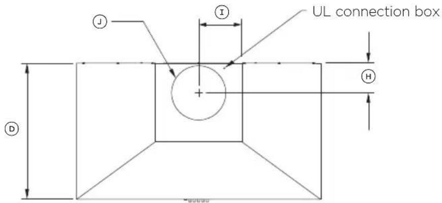
text_image
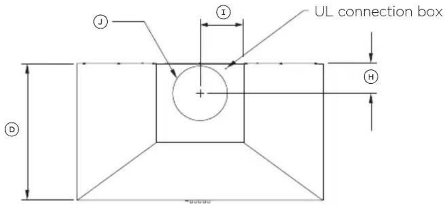
UL connection box J I H DPLAN

text_image
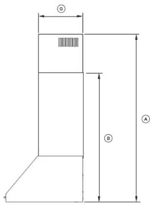
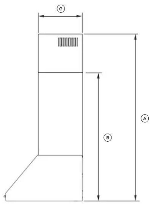
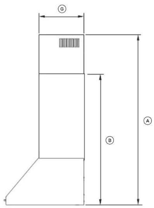
G B A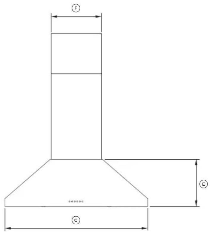
text_image
F E CFRONTPROFILE
text_image
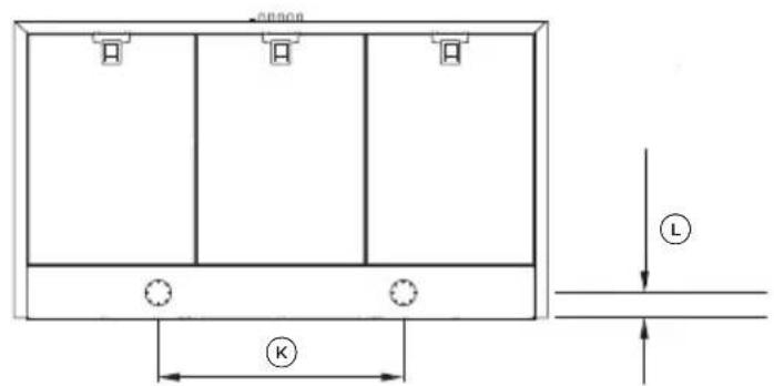
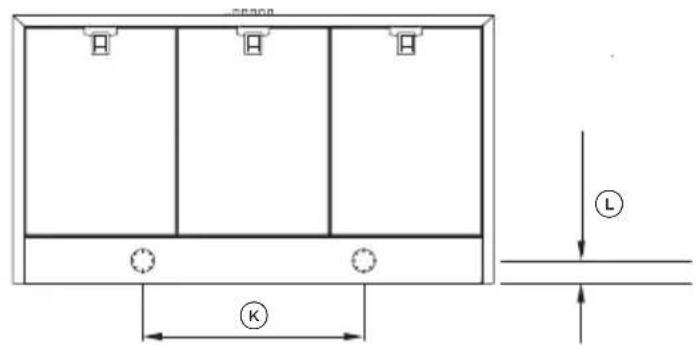
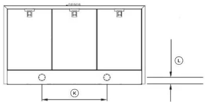
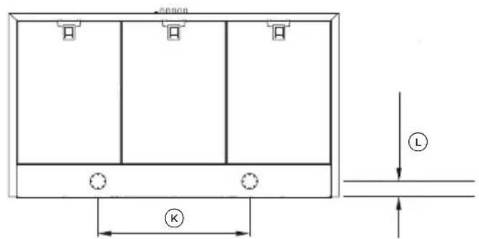
censor K LBOTTOM
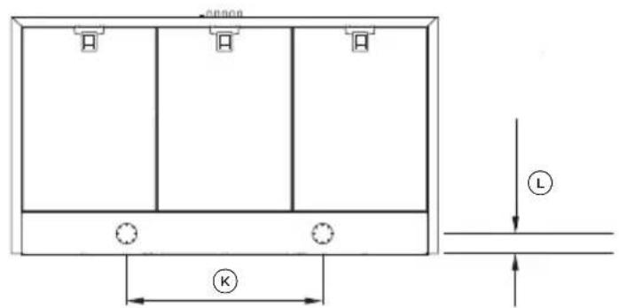
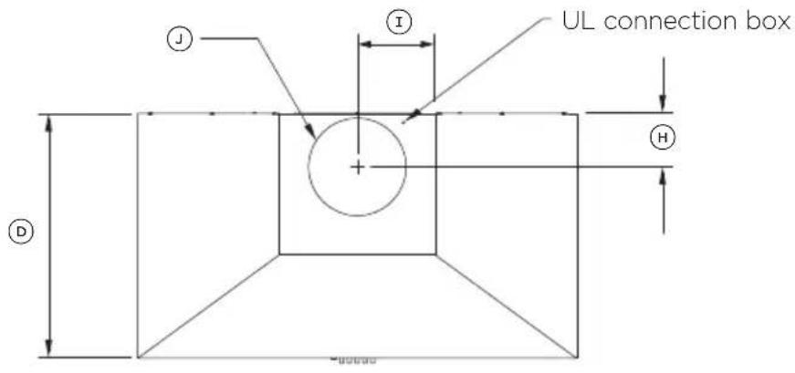
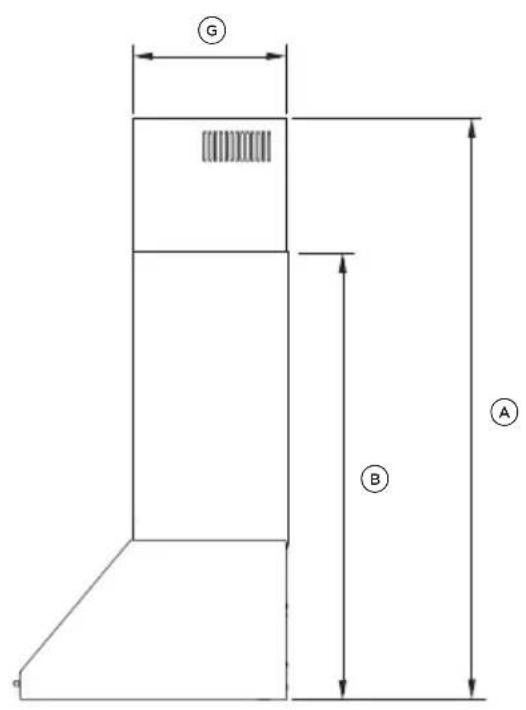
| PRODUCT DIMENSIONS | HC24 | |
| IN | MM | |
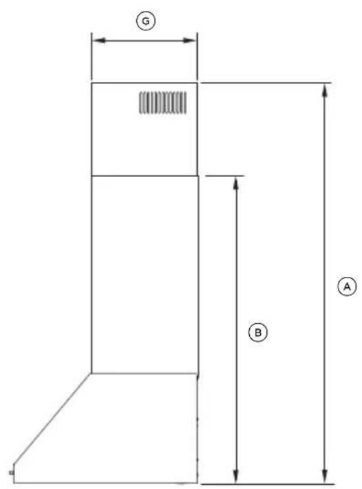
| A Maximum overall height of product | 38 3/8 | 975 |
| B Minimum overall height of product 25 1/16 636 | ||
| C Overall width of product | 23 9/16 | 598 |
| D Overall depth of product 19 11/16 500 | ||
| E Height of product 11 3/4 298 | ||
| F Width of chimney 12 5/8 320 | ||
| G Depth of chimney 11 7/16 290 | ||
| H Distance from center of ducting outlet to back of product | 4 5/16 | 110 |
| I Distance from center of ducting outlet to side of chimney | 6 5/16 | 160 |
| J Diameter of ducting outlet | 7 7/8 | 200 |
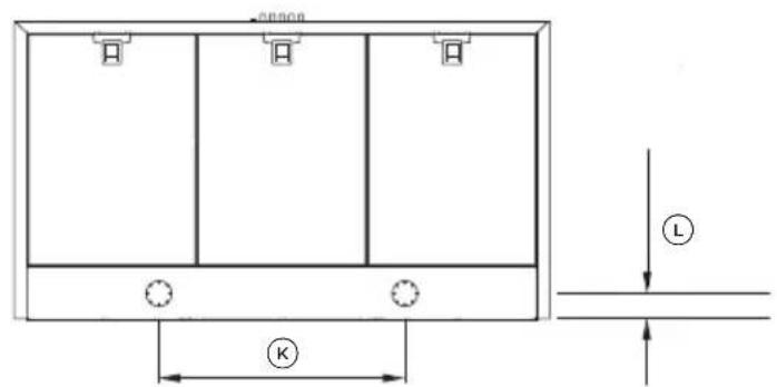
| K Distance between center of lights | 16 1/4 | 413 |
| L Distance between center of lights and back of product | 1 5/8 | 42 |
Actual product dimensions may vary by ± 1/16' (2 mm).
*Maximum overall height of product with chimney extension= 57" 1450mm.
text_image
UL connection box I J H DPLAN
text_image
G B A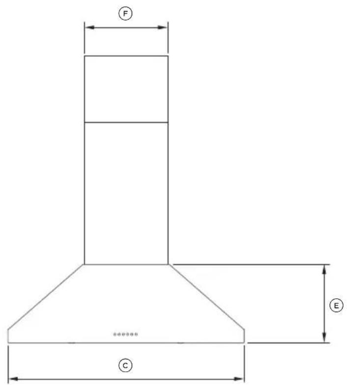
text_image
F E CFRONTPROFILE
text_image
censor K LBOTTOM
| PRODUCT DIMENSIONS | HC30 | |
| IN | MM | |
| A Maximum overall height of product | 38 3/8 | 975 |
| B Minimum overall height of product 25 1/16 636 | ||
| C Overall width of product 29 3/4 755 | ||
| D Overall depth of product 19 11/16 500 | ||
| E Height of product 11 3/4 298 | ||
| F Width of chimney 12 5/8 320 | ||
| G Depth of chimney | 11 7/16 | 290 |
| H Distance from center of ducting outlet to back of product | 4 5/16 | 110 |
| I Distance from center of ducting outlet to side of chimney | 6 5/16 | 160 |
| J Diameter of ducting outlet | 7 7/8 | 200 |
| K Distance between center of lights | 16 1/4 | 413 |
| L Distance between center of lights and back of product | 1 5/8 | 42 |
Actual product dimensions may vary by ± 1/16' (2 mm).
*Maximum overall height of product with chimney extension= 57" 1450mm.
text_image
UL connection box J I H DPLAN
text_image
G B A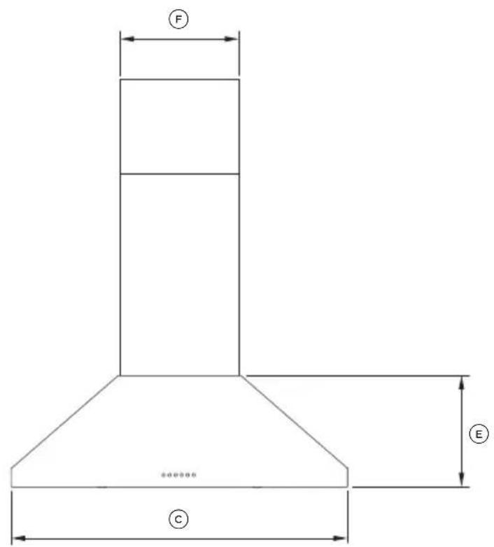
text_image
F E CFRONTPROFILE
text_image
censor K LBOTTOM
| PRODUCT DIMENSIONS | HC36 | |
| IN | MM | |
| A Maximum overall height of product | 38 3/8 | 975 |
| B Minimum overall height of product 25 1/16 636 | ||
| C Overall width of product | 35 3/8 | 898 |
| D Overall depth of product 19 11/16 500 | ||
| E Height of product 11 3/4 298 | ||
| F Width of chimney 12 5/8 320 | ||
| G Depth of chimney | 11 7/16 | 290 |
| H Distance from center of ducting outlet to back of product | 4 5/16 | 110 |
| I Distance from center of ducting outlet to side of chimney | 6 5/16 | 160 |
| J Diameter of ducting outlet | 7 7/8 | 200 |
| K Distance between center of lights | 16 1/4 | 413 |
| L Distance between center of lights and back of product | 1 5/8 | 42 |
Actual product dimensions may vary by ± 1/16' (2 mm).
*Maximum overall height of product with chimney extension= 57" 1450mm.
text_image
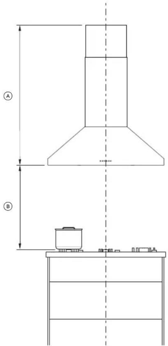
A B| HEIGHT DIMENSIONS IN MM | |||
| A Ducted installation | |||
| • Minimum height | 25 1/16 | 636 | |
| • Maximum hieght | 38 3/8 | 975 | |
| Recirculation | |||
| • Minimum height | 26 5/8 | 676 | |
| • Maximum hieght | 38 3/8 | 975 | |
| B Height top of cooktop to base of product | 26-30 | 660-762 | |
*Maximum height can be extended with the optional chimney extension
This range hood must be installed no lower than the minimum height indicated in the table above. Minimum installation height may be greater if required by the cooktop, refer to your cooktop installation instructions.
Installation at the minimum height will improve the efficiency of capturing cooking odours, grease and smoke. Installation above the minimum height is the users preference, it is not recommended to install above the maximum height indicated in the table above.
text_image
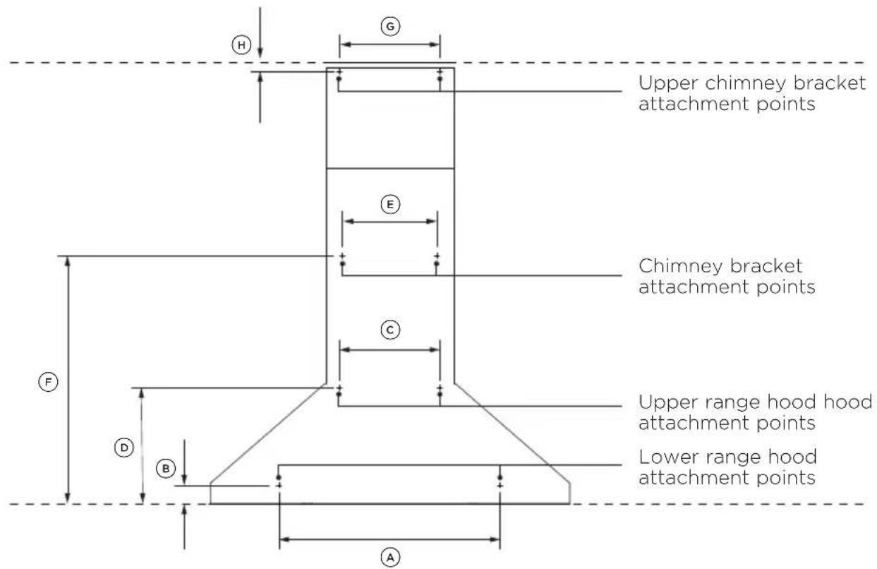
Upper chimney bracket attachment points Chimney bracket attachment points Upper range hood hood attachment points Lower range hood attachment points| ATTACHMENT DIMENSIONS IN MM | |||
| A | Lower range hood attachment point width 20 508 | ||
| B | Lower range hood attachment point height | 1 3/4 | 45 |
| C | Upper range hood attachment point width | 9 7/8 | 250 |
| D | Upper range hood attachment point height | 11 1/4 | 286 |
| E | Chimney bracket attachment point width | 9 7/8 | 250 |
| F | Chimney bracket attachment point height | 31 1/4 | 794 |
| G | Upper chimney bracket attachment point width | 9 7/8 | 250 |
| H | Upper chimney bracket attachment point height | 1 | 25 |
Attention should be given to ensure that any applicable regulations concerning the discharge of exhaust air are fulfilled.
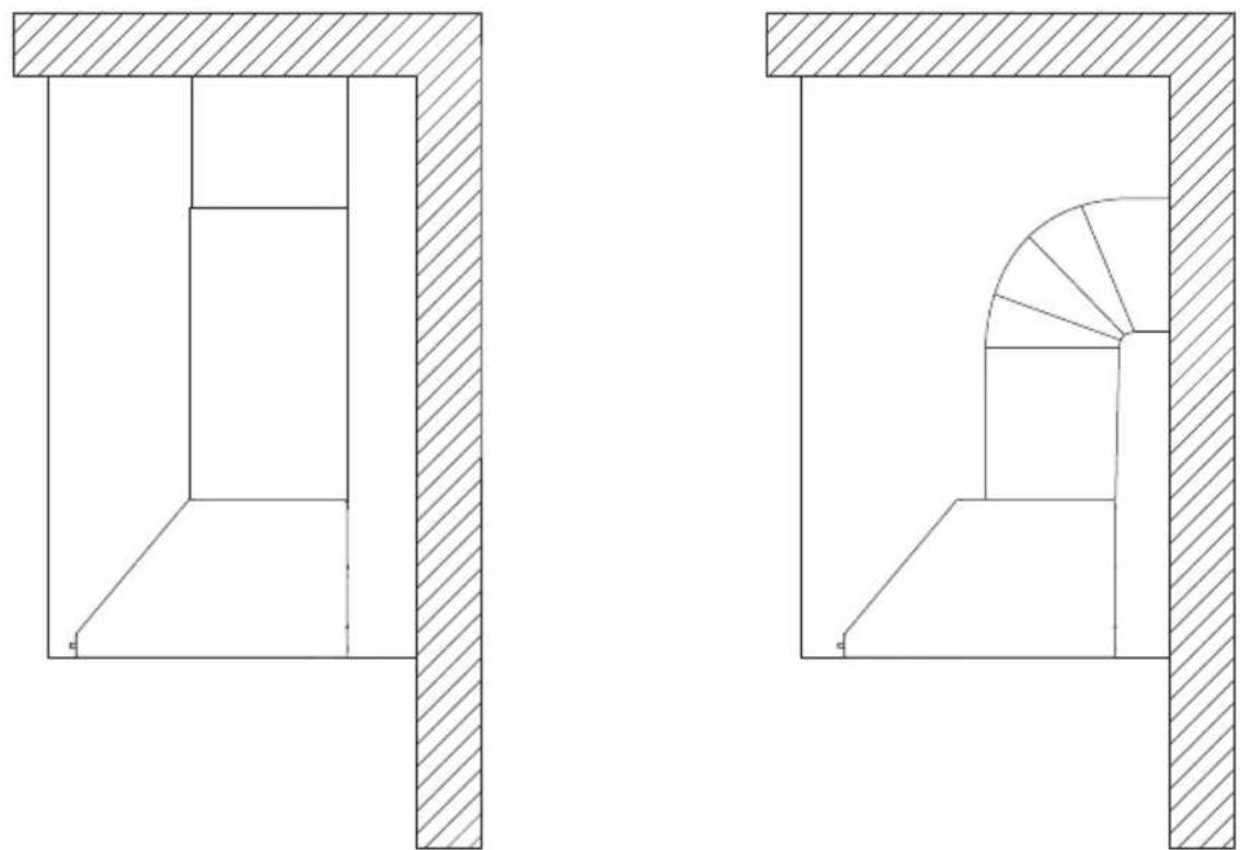
Ducted
It is recommended that 8" (203mm) diameter, rigid or semi-rigid ducting is used. This will require a 8 1/4" (210mm) (min) round hole in the ceiling or wall. Care should be taken to position the hole correctly.
For optimal efficiency use the shortest and straightest duct route possible and use rigid or semi-rigid ducting for reduced noise and increased airflow. Flexible metal ducting should only be used as a last resort (ie in difficult installations) and if used ensure that it is straight, smooth and extended as much as possible.
natural_image
Technical drawing showing two mechanical assembly views with hatched sections and internal components (no text or symbols)Recirculating
To enable the product to operate with the air recirculating, purchase a recirculation diverter and carbon filters (refer to the “Parts and accessories” section). This recirculation diverter is required to channel the air out the side vents at the top of the chimney and the carbon filters are required to remove odors.
A ducting hole is not required in the wall or ceiling if the ventilation hood is installed to operate with exhaust air recirculating.
①
natural_image
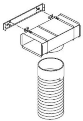
Technical line drawing of a mechanical assembly with a cylindrical component (no text or symbols)Centre and secure the chimney brackets using two 30mm self tapping screws per bracket.
②
natural_image
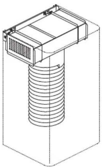
Technical line drawing of a mechanical component with coiled spring and housing (no text or symbols)Align recirculation adapter to the upper bracket. Fit using 30mm Phillips screws.
For installation of the remaining chimney duct and hood refer to “Attach brackets and mounting screws” and “Attach chimney” sections for instructions.
natural_image
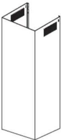
Simple line drawing of a rectangular box with two side tabs (no text or symbols)The 33 1/2" (850mm) chimney extension is an optional extra used when extra height is required in high ceiling situations. Suits models HC24PCX, HC30PCB1, HC30PCR1, HC30PCX1, HC30PCW1, HC36PCB1, HC36PCR1, HC36PCX1, HC36PCW1. Coverduct extensions are available depending on the color of rangehood (refer to the "Parts and accessories" section).
The extension replaces the existing upper cover that is supplied with the rangehood. Coverduct extension is to be installed following the same steps as the upper cover extension (refer to “Attach brackets and mounting screws” and “Attach chimney” sections for installation instructions)
text_image
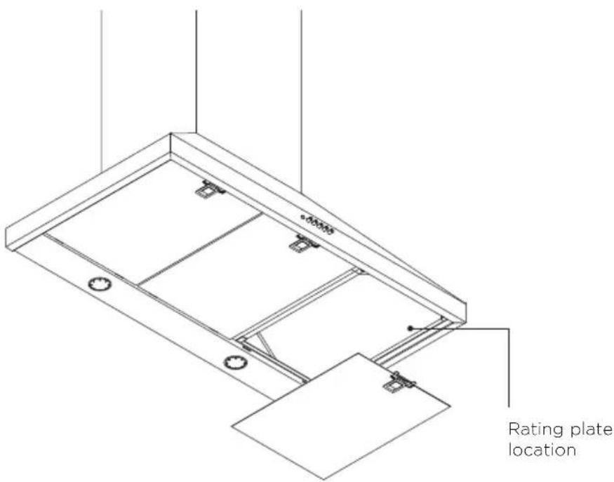
ANSYS Rating plate locationBefore connecting the range hood to the power supply, ensure the voltage and frequency indicated on the rating plate match that of the installation location.
Warning: Failure to install the screws or fixing device in accordance with these instructions may result in an electrical hazards.
natural_image
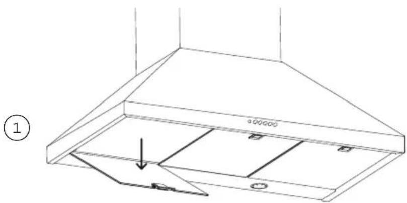
Technical line drawing of a ceiling structure with ventilation duct and mounting holes (no text or symbols)Remove the filters -pull the catch and tilt the filter downwards until it disengages from the supports.
1
natural_image
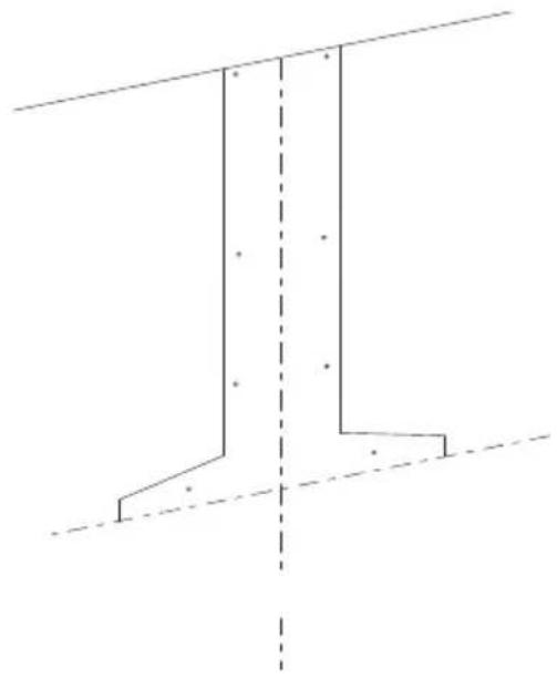
Pure geometric line drawing of a structural L-shape with dashed symmetry lines (no text or symbols)Temporarily mark the height of the bottom of the range hood and the centre of the cooktop on the wall according to the information provided in "Installation height".
②
natural_image
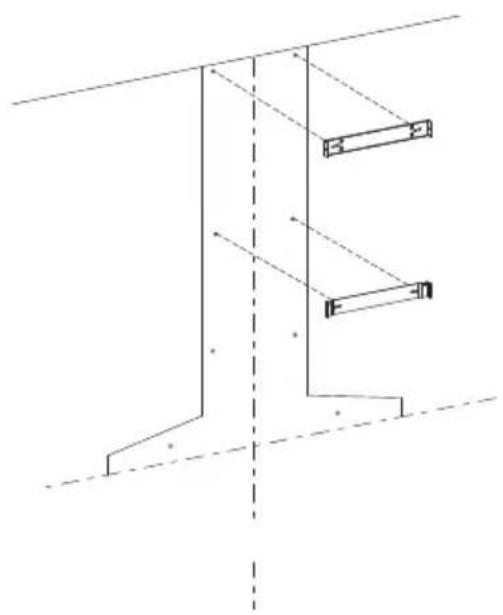
Pure architectural line drawing of a staircase with no text, numbers, or symbolsAttach the chimney bracket and upper chimney bracket (if using the upper chimney). Use the 1 3/16" (30mm) screws and expansion plugs if attaching to masonry.
③
text_image
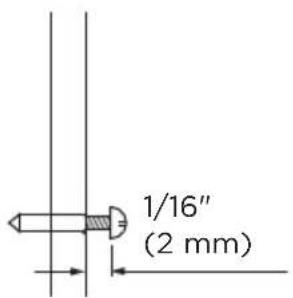
1/16" (2 mm)Attach the upper hood mounting screws. Use the 1 3/16" (30mm) screws and expansion plugs if attaching to masonry.
Ensure that there is a 1/16" (2mm) gap between the screw head and the wall.
natural_image
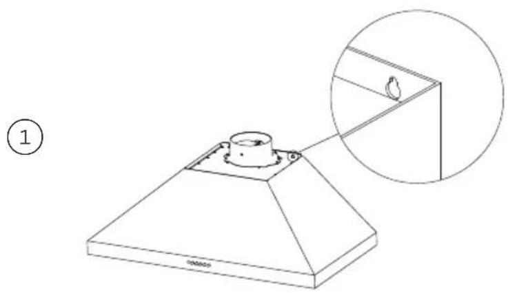
Technical line drawing of a conical lamp or fixture with a base, showing a close-up inset detail (no text or symbols)Hang the range hood off the upper range hood mounting screws with 1/16" (2mm) gap. Hang off the keyhole attachment points on the back of the range hood then tighten the screws.
natural_image
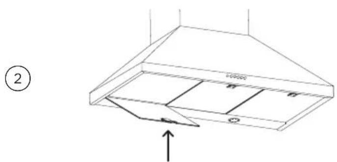
Technical line drawing of a ceiling structure with ventilation duct and mounting points (no text or symbols)Attach the lower range hood mounting screws to fix the range hood to the wall. Refit the filters.
natural_image
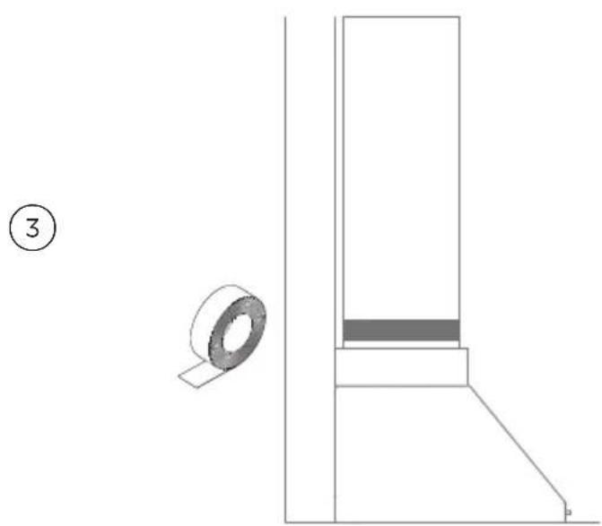
Technical line drawing of a mechanical assembly with a circular component and a rectangular block (no text or symbols)Attach ducting to the ducting adapter using aluminium duct tape.
natural_image
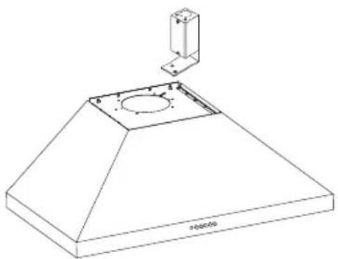
Technical line drawing of a conical mechanical component with a mounting bracket and circular cutout (no text or symbols)① Run three wires from the power connection box on the rangehood to the power point.
② Two wires for the power supply and one for the ground wire.
Open the power connection box on the range hood and secure the power conductor with a strain relief (not included).
③ Connect the power conductors to the conductors for the range hood, black to black and white to white.
④ Connect the grounding wire (green or bare) to the ground conductor (green) of the range hood power connection box.
Secure all the connections with wire nuts.
Replace the power connection box cover.
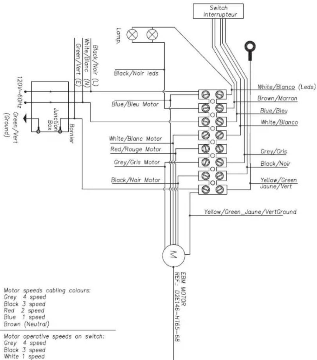
text_image
Switch Interrupteur Lamp. Black/Noir leds White/Blanco (Leds) Brown/Marran Blue/Bleu White/Blanco Blue/Bleu Motor Grey/Gris Blue/Noir Yellow/Green Jaune/Vert Green/Vert (Ground) 120V~60Hz junction Box Barnier M EBM MOTOR REF.: D2E146-HT65-68 Yellow/Green_Jaune/VertGround Motor speeds cabling colours: Grey 4 speed Black 3 speed Red 2 speed Blue 1 speed Brown (Neutral) Motor operative speeds on switch: Grey 4 speed Black 3 speed White 1 speed①
natural_image
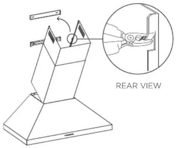
Technical line drawing of a mechanical assembly with an inset showing a close-up of a component being cut (no text or symbols present)Bend the tabs on the chimney.
②
natural_image
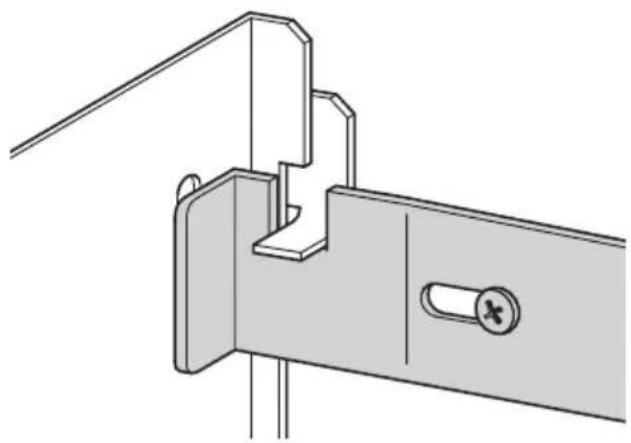
Technical line drawing of a mechanical bracket or latch mechanism (no text or symbols)Place chimney around the range hood chassis and hang off the chimney bracket.
③
natural_image
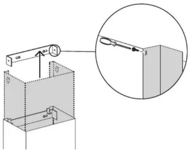
Technical diagram showing a mechanical assembly with an inset close-up of a tool interacting with a component (no text or symbols present)Extend the upper chimney and attach to the upper chimney bracket with 10mm screws.
TO BE COMPLETED BY THE INSTALLER
Range hood is correctly installed and all connections are secure.
Connections have not pierced any electrical or water lines within the wall.
Ducting has not been crushed or bent in any area's.
Flexible ducting has been pulled taut and any excess removed (if required).
Power mains switch is accessible to the customer and switched on.
Operation of the product has been tested, refer to user guide.
Complete and keep for safe reference:
Model
Serial no.
Purchase date
Purchaser
Dealer address
Installer's name
Installer's signature
Installation company
Installation date
FISHERPAYKEL.COM
© Fisher & Paykel Appliances 2024. All rights reserved.
The models shown in this guide may not be available in all markets and are subject to change at any time.
The product specifications in this guide apply to the specific products and models described at the date of issue. Under our policy of continuous product improvement, these specifications may change at any time.
For current details about model and specification availability in your country, please go to our website or contact your local Fisher & Paykel dealer.
FISHER & PAYKEL
HOTTE CHEMINÉE MURALE DE FORME PYRAMIDALE
CLASSIQUE
HC24PCX1, HC30PCX1, HC30PCB1, HC30PCR1, HC30PCW1, HC36PCX1, HC36PCB1, HC36PCR1 & HC36PCW1
GUIDE D'UTILISATION
US CA
natural_image
Line drawing of a ceiling structure with ventilation duct and ventilation grilles (no text or symbols)Retirez les filtres en aluminium.
②
natural_image
Hand holding a circular object with an arrow indicating rotation (no text or symbols)natural_image
Simple line drawing of a ceiling lamp with a conical shade and downward arrow, no text or symbols present.natural_image
Technical line drawing of a ceiling structure with ventilation duct and mounting bracket (no text or symbols)natural_image
Isometric line drawing of a metal HVAC chimney (no text or symbols)Hotte (1)
text_image
PIRES & PATIEL HOTTE CHEMINE MURALE DE FORME SYTRAPICALS —— JOURNAL HOTTEL & PATIEL SYTRAPICALSnatural_image
Simple line drawing of a 3D rectangular box with a vertical slot on top (no text or symbols)Cheminée (1)
natural_image
Simple line drawing of a 3D box with two side compartments (no text or symbols)natural_image
Technical line drawing of a mechanical component with mounting base (no text or symbols)natural_image
Isometric line drawing of a rectangular metal bracket with cutouts and mounting holes (no text or symbols)natural_image
Simple line drawing of a metal bracket with two side slots (no text or symbols)natural_image
Simple line drawing of a rectangular box with two side slots (no text or symbols)text_image
Boîtier de raccordement UL J I H DEN PLAN
text_image
G A B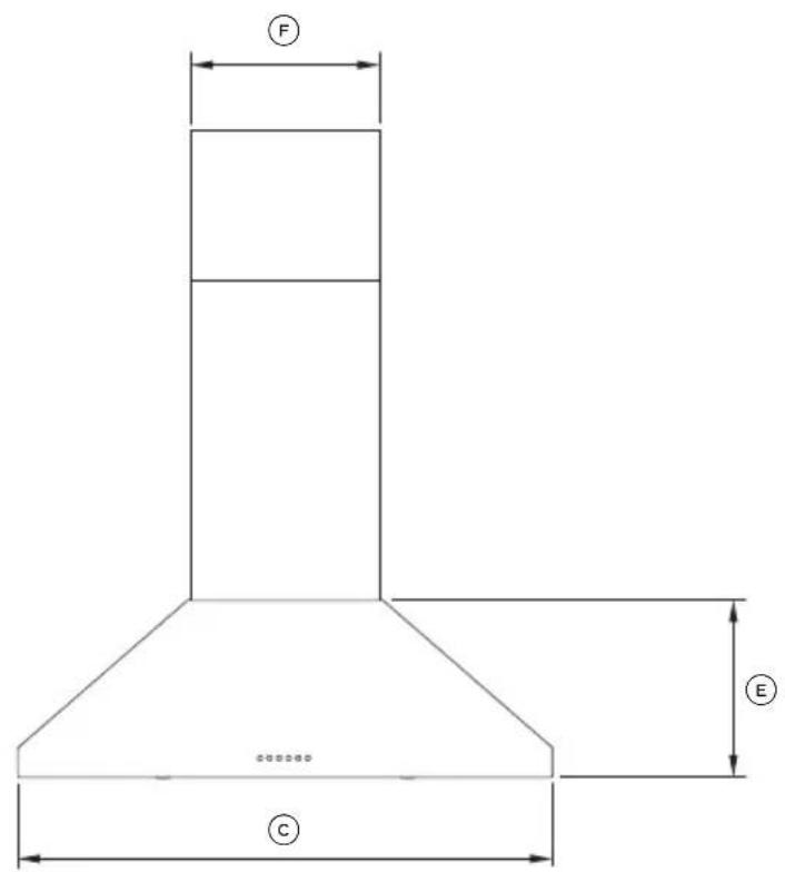
text_image
F E CAVANTPROFIL
text_image
C2008 K LDESSOUS
text_image
Boîtier de raccordement UL J I H DEN PLAN
text_image
G B A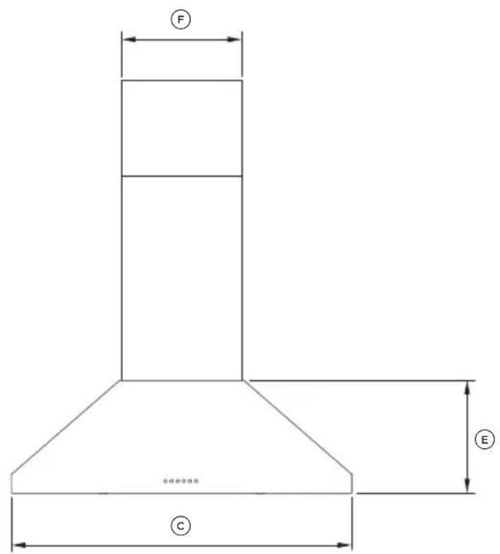
text_image
F E CAVANTPROFIL
text_image
censor L KDESSOUS
text_image
Boîtier de raccordement UL J I H DEN PLAN
text_image
G B A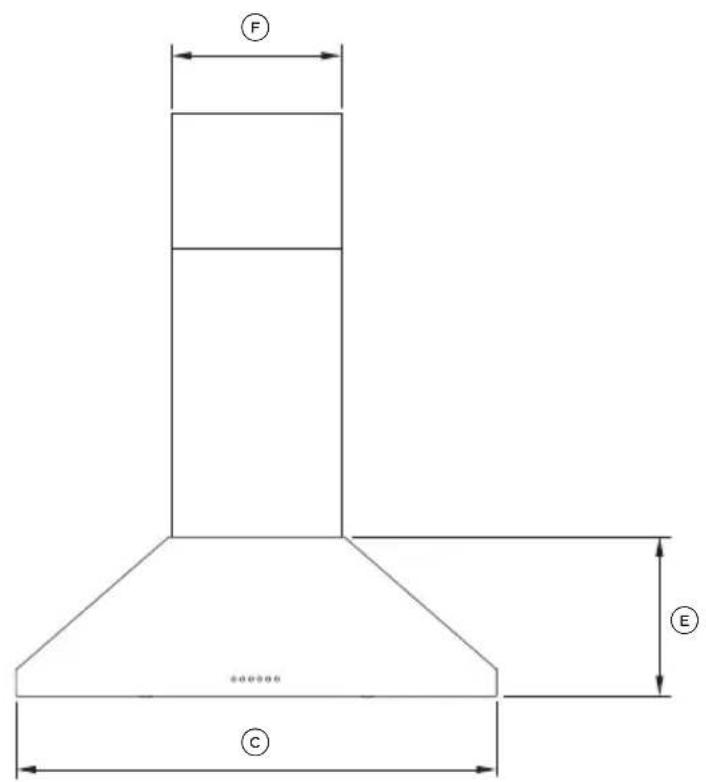
text_image
F E CAVANTPROFIL
text_image
censor L KDESSOUS
natural_image
Pure technical line drawing of a mechanical part with hatched sections and dimension lines (no text or symbols)