
VLS 504A AC - Refrigerator VESTFROST - Free user manual and instructions
Find the device manual for free VLS 504A AC VESTFROST in PDF.




| Product type | Vaccine refrigerator |
| Brand | Vestfrost |
| Model | VLS 504A AC |
| Supply voltage | 220-240 V |
| Frequency | 50 Hz |
| Electrical protection | Fuse/circuit breaker 10-13 A |
| Refrigerant | Flammable hydrocarbons (type indicated on rating plate) |
| Minimum room volume | 1 m³ per 8 g of refrigerant |
| Storage temperature range | +2 °C to +8 °C |
| Thermostat type | Electronic, factory set |
| Temperature display | Solar thermometer |
| Switch | On/Off |
| Voltage stabilizer recommendation | Yes, to protect against fluctuations |
| Cleaning | Hot water, unscented detergent, soft cloth |
| Seal maintenance | Clean regularly with clean water |
| Condensation drainage | Via internal drain plug |
| Defrosting | Manual, without sharp-edged tools |
| Spare parts | Order with product type and number |
| Standards | EU Directives 2014/35/EU and 2014/30/EU |
Frequently Asked Questions - VLS 504A AC VESTFROST
User questions about VLS 504A AC VESTFROST
0 question about this device. Answer the ones you know or ask your own.
Ask a new question about this device
Download the instructions for your Refrigerator in PDF format for free! Find your manual VLS 504A AC - VESTFROST and take your electronic device back in hand. On this page are published all the documents necessary for the use of your device. VLS 504A AC by VESTFROST.
USER MANUAL VLS 504A AC VESTFROST
12
RESPONSIBLE CONSUMPTION AND PRODUCTION

Vestfrost Solutions is working towards reaching the UN - Global Sustainable Development Goals by 2030.
The Sustainable Development Goals are the blueprint to achieve a better and more sustainable future for all.
In order to implement Goal no 12 "Responsible Consumption and Production", this manual has been printed on recycled paper.

ILR Refrigerator Model VLS 204A/304A/354A/404A/504A AC
GB Instructions for use
As the appliance contains flammable refrigerant, as stated on nameplate, it is essential to ensure that the refrigerant pipes are not damaged.
The quantity and type of the refrigerant used in your appliance is indicated on the rating plate.
Standard EN378 specifies that the room in which you install your appliance must have a volume of 1 m3 per 8 g of hydrocarbon refrigerant used in the appliances. This is to avoid the formation of flammable gas/air mixtures in the room where the appliance is located in the event of a leak in the refrigerant circuit.
WARNING:
Ventilation openings in the appliance or in built-in structures must be kept clear.
WARNING:
Do not use other mechanical devices or means to accelerate the defrosting process or to remove rime other than those recommended by the manufacturer.
WARNING:
Do not damage the refrigerant system.
WARNING:
The appliance may not be exposed to rain.
WARNING:
This appliance is not intended for use by persons (including children) with reduced physical, sensory or mental capabilities, or lack of experience and knowledge, unless they have been given supervision or instructions concerning use of the appliance by a person responsible for their safety. Children should be supervised to ensure that they do not play with the appliance.
WARNING:
Children must not play with, on, or around the appliance.
WARNING:
Children must not clean the appliance or carry out general maintenance unless they are at least 8 years old and are being supervised.
WARNING:
Always keep the keys in a separate place and out of reach of children.
WARNING:
Before servicing or cleaning the appliance, switch off the circuit breaker.

WARNING:
Danger: risk of fire or explosion. Flammable refrigerant used, as stated on the nameplate. To be repaired only by trained personnel.
WARNING:
Do not store explosive substances such as aerosol cans with a flammable propellant in this appliance.
WARNING:
When positioning the appliance, ensure the power cord is not trapped or damaged.
WARNING:
Do not locate multiple portable socket-outlets or portable power supplies at the rear of the appliance.
WARNING:
Do not use electrical appliances inside the food storage compartments of the appliance, unless they are of the type recommended by the manufacturer.
WARNING:
Appliance uses flammable insulation blowing gas. For information about safe disposal, please contact your local disposal service. See section for Disposal.
Contents
WARNING 2
Get to know your Refrigerator ....5
HIGHLY IMPORTANT! 6
Placing the Fridge-tag ® 7
General information 8
Voltage stabilizers 9
Electrical connection ......9
Operation and function ......10
Loading the appliance ....11
Maintenance and cleaning ....12
Condensation water drainage ....13
Trouble shooting ....14
Warranty, spare parts and service .....15
Disposal 16
| PQS Code | Model PQS Performance specificationsSpecification reference: | PQS Independent type-testing protocolProduct verification protocol: | |
| E003/109 VLS | 204A AC E003 | /RF03.4 E003/RF03-VP.3 | |
| E003/110 VLS | 304A AC E003 | /RF03.4 E003/RF03-VP.3 | |
| E003/111 VLS | 354A AC E003 | /RF03.4 E003/RF03-VP.3 | |
| E003/112 VLS | 404A AC E003 | /RF03.4 E003/RF03-VP.3 | |
| E003/113 VLS | 504A AC E003 | /RF03.4 E003/RF03-VP.3 | |
Get to know your Refrigerator
WARNING!
HIGHLY IMPORTANT!
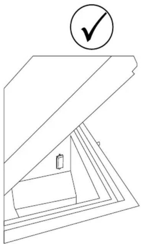
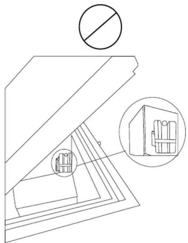
- Make sure NEVER to place any commodities up against the sensor cover.
Eg. Water-pack
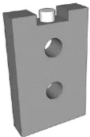
fig. 2
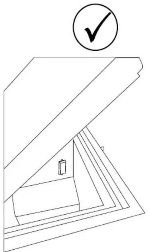
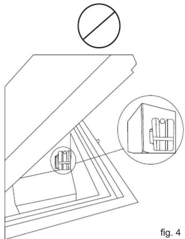
fig. 4 fig. 3
Placing the Fridge-tag ®
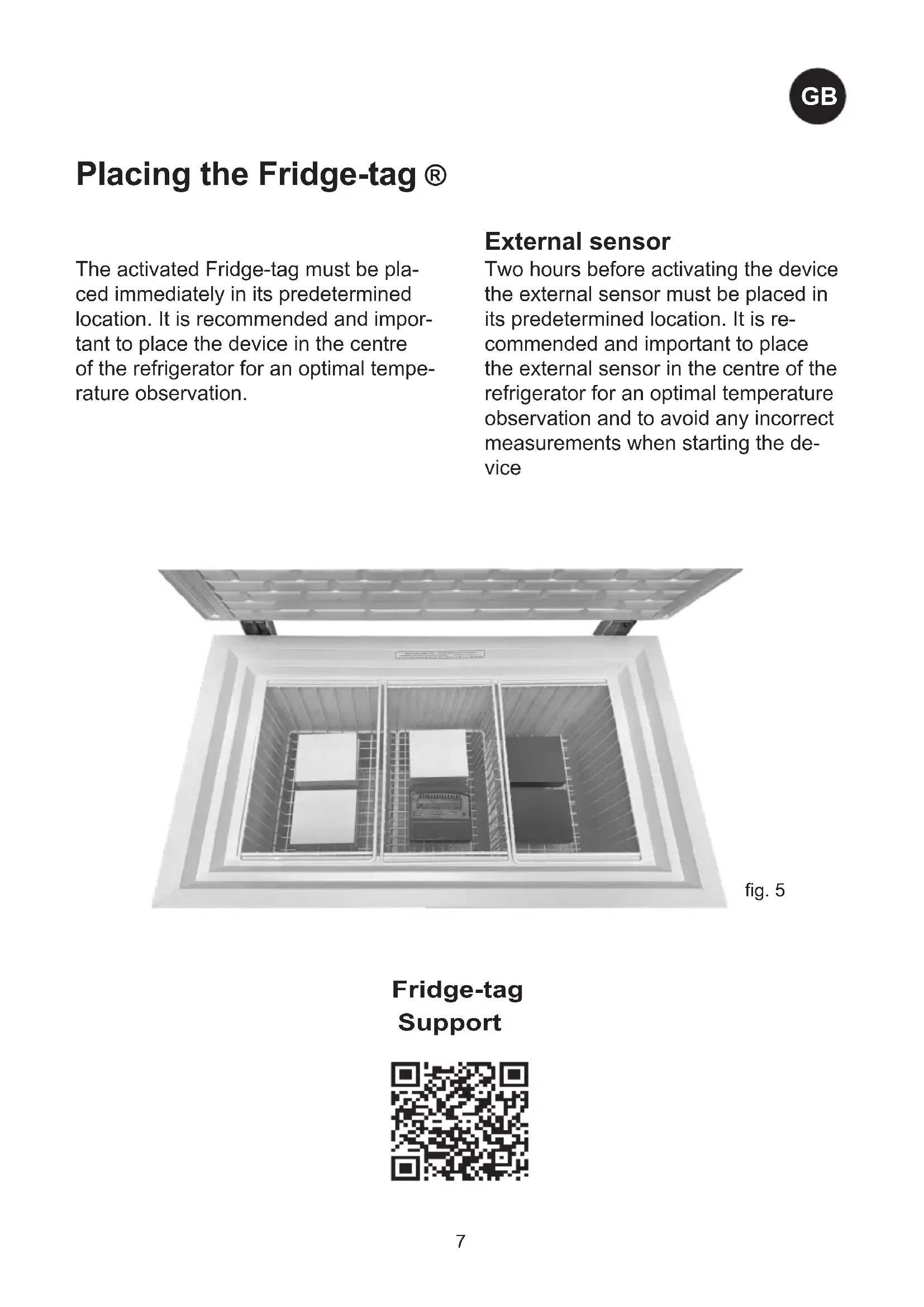
The activated Fridge-tag must be placed immediately in its predetermined location. It is recommended and important to place the device in the centre of the refrigerator for an optimal temperature observation.
External sensor
Two hours before activating the device the external sensor must be placed in its predetermined location. It is recommended and important to place the external sensor in the centre of the refrigerator for an optimal temperature observation and to avoid any incorrect measurements when starting the device
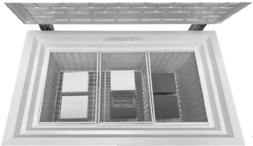
fig. 5
Fridge-tag
Support
General information
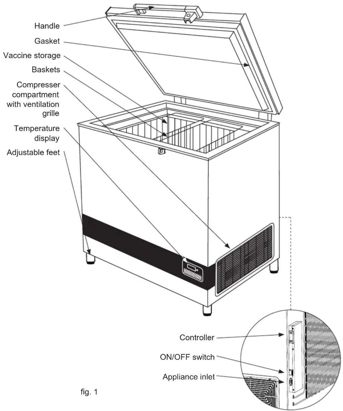
The VLS A AC is an ice-lined vaccine refrigerator. It has one compartment for vaccine storage (+2 to +8°C) equipped with baskets that are recommended to be used.
Power supply
The VLS A AC line is equipped with a heavy-duty compressor that can operate at voltages 22% below nominal voltage. See the rating plate. If voltage variations go beyond this range, it is recommended to use an automatic voltage stabilizer.
Technical data
See the rating plate, which is placed at the rear side of the appliance.
Unpacking
- Unpack the appliance and check that it has not been damaged. If you observe any damage, inform your supervisor.
- Check the rating for correct voltage and frequency.
- Open and remove all internal packing material.
Adjustable feet
Level the appliance by screwing the adjustable feet up or down.
If the appliance is to be placed on a soft surface, e.g. floorboards or a carpet, it is best to recheck whether the appliance is still level after a period of time as the underlying surface may give under the weight of the appliance.
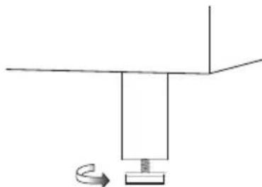
fig. 6
Location
The appliance must be placed in a well ventilated room, not in direct sunlight and away from other heating sources.
When installing the appliance please ensure that the floor is level. Please see figure 6 for further directions.
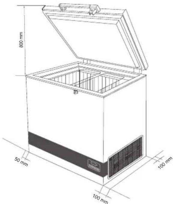
fig. 7
There must be at least 30 mm clearance between the base of the appliance and the floor.
IMPORTANT! There must be free access to the ventilation grille (fig.8).
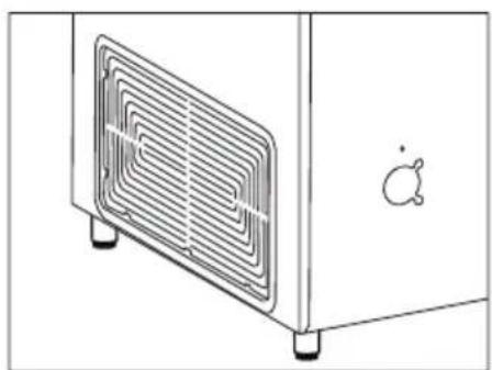
fig. 8
Voltage stabilizers
It is highly recommended that all cold chain equipment running on AC current is installed with a voltage stabilizer, in order to safeguard the equipment against voltage fluctuations.
Stabilizers should be selected and installed as per the input voltage available.
Instructions to User:
- Every refrigeration unit must be connected to an individual stabilizer.
- Bypassing of Stabilizer is not recommended, as such practice may lead to damage of the CCE and in turn safety of vaccines and hence must be avoided.
- Proper earthing should be available and connected.
- Emphasize on repairing stabilizers immediately. Identify authorized Vestfrost service provider in case of technical assistance is required.
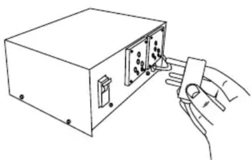
The voltage stabilizer is also provided with arrangement to cut off its output voltage to the ILR in case the mains voltage goes below or above as per designed input voltage range. The output is restored automatically after the factory set delay 3 to 6 minutes (WHO/PQS E007/VS01.4 specifications) when the mains voltage is within the recommended range and remains within.
Electrical connection
Wiring and connections in power supply systems must be all applicable (local and national) electrical codes. Consult these codes lengths and sizes prior to cabinet installation.
This device complies with relevant EU directives including Low Voltage Directive 2014/35/EU and Electromagnetic Compatibility Directive 2014/30/EU
The socket should be freely accessible.
Connect the appliance only to 220/240 V / 50Hz alternating current via a correctly installed earthed socket.
The socket must be fused with a 10-13 A fuse.
If the appliance is to be operated in a non-European country, check on the rating plate whether the indicated voltage and current type correspond to the values of your mains supply.
Information regarding voltage, current or power is given on the rating plate.
The power cord may be replaced by a technician only.
The rating plate provides various technical information as well as type and serial number.
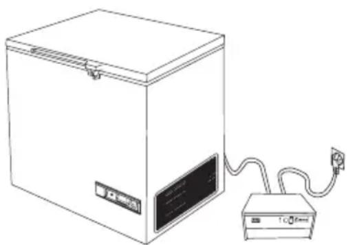
Connect the appliance to a voltage stabilizer and connect the voltage stabilizer to the wall socket. (Fig 9+10)
Operation and function
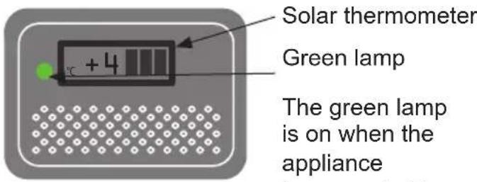
fig. 11 the power supply.
Starting procedure
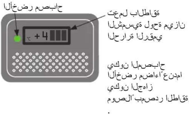
Connect the mains lead to the power supply/voltage stabilizer. The green lamp must light (fig. 11) to indicate that the appliance is operating. The electronic thermostat makes a self-test, 20 seconds before the compressor starts.
Temperature control
It is recommended to check the inside temperature with an accurate thermometer twice a day. The inside temperature must be checked regularly according to WHO's standards and specifications.
Cool down of the appliance
Before the appliance is loaded with vaccines, the ice-lining must be frozen. To ensure that the ice-lining is frozen, do the following:
- Place a thermometer in the top basket.
- Let the refrigerator run for at least 48 hours before loading vaccine.
- Check the temperature in the vaccine compartment (must be between +2° and +8°C).
The temperature in the vaccine compartment must always be monitored on the thermometer and be within the range +2° to +8°C. Due to tolerance of the thermostat you should always control the temperature during cool down.
Controller
The appliance has a controller that controls the temperature in the vaccine compartment. The controller is factory adjusted to a default setpoint, what in most ambient environments will keep the vaccine compartment within desired thresholds of +2° to +8°C.
If the cooler is not used for a longer period of time, it is recommended to use the ON/OFF switch to turn the cooler OFF. This disconnects the power from mains.
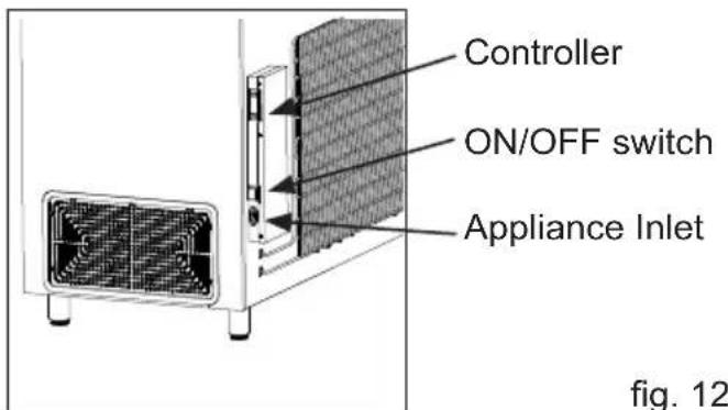
In case cooler is turned OFF, make sure the vaccine compartment is cleaned and dried thoroughly afterwards, this to prevent problems with odors or mold. To prevent odors taking hold it is highly recommended to keep the lid slightly open.
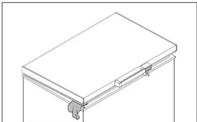
fig. 13
Loading the appliance
Loading vaccines
When the temperature in the vaccine compartment has stabilized, i.e. and the temperature is between +2° and +8°C and the compressor stops and starts, vaccines can be loaded. The vaccines should be placed and arranged in the baskets.
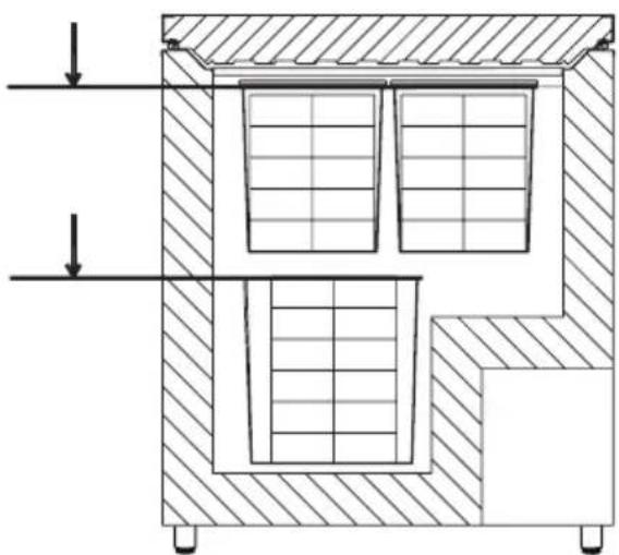
To ensure air-circulation and prevent too low vaccine temperature, direct contact to the inside walls must be avoided. The Vaccine load in the baskets shall not be above top of the baskets. (fig. 15)
Vaccine storage
Below points are recommended vaccine storage advice outlined by Unicef.
- Keep the vaccine boxes containing the vaccines in neat rows.
- Different vaccines should be kept separately to facilitate easy identification.
- Keep about 2 cm space between boxes of vaccines for circulation of air.
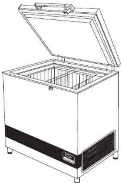
fig. 14
- Store freeze-sensitive vaccines (DPT, TT, IPV, Penta and Hep. B) away from the bottom of the ILR to avoid freezing. Always keep the vaccines in the basket provided in the ILR. OPV, RVV, BCG, JE and Measles vaccine to be stored at bottom of basket of the ILR. ● Vaccine should be stored as per their heat and cold sensitivity.
Do not load the vaccine above top of the baskets.
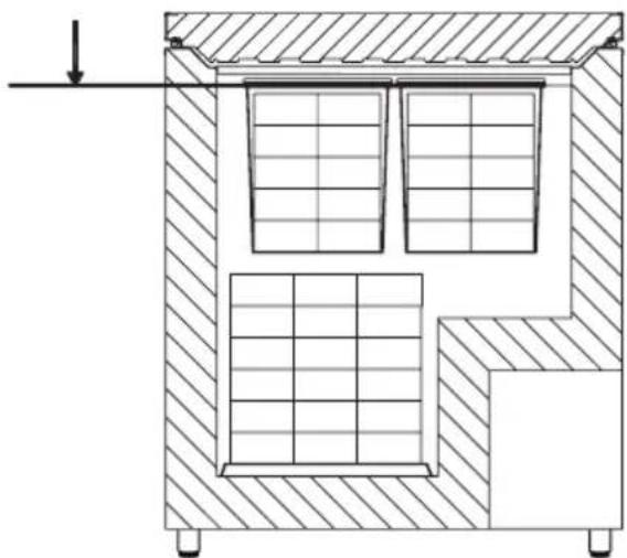
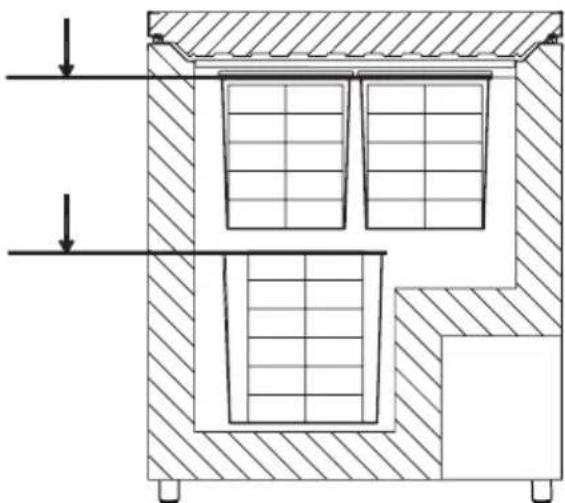
fig. 15
Maintenance and cleaning
Daily maintenance:
The temperature in the vaccine compartment must always be monitored on the thermometer every day. Please note that the vaccine in the appliance must not freeze.
Weekly maintenance:
During normal use, water can accumulate at the bottom of the appliance; remove with a cloth or through the drainage hole. Wipe off water droplets on the inside wall at the same time.
Check if lid gasket is sealing tight to the top frame when the lid is closed. A tight sealing lid reduces accumulation of water and formation of rime significantly.
Monthly maintenance:
Clean the grille on the right side of the refrigerator once each month. Clean vaccine compartment with lukewarm water and mild detergent. Clean outside of refrigerator with lukewarm water and mild detergent.
Yearly maintenance:
Electric connections and components are to be checked and cleaned once a year or more if necessary.
Cleaning
Disconnect the power supply before cleaning. The best way to clean the appliance is by using lukewarm water with a small amount of unscented detergent. Never use cleaning agents that scour. Use a soft cloth. Rinse with clean water and dry thoroughly. It is important to prevent water from running into the control panel.
The gasket around the lid must be cleaned regularly to prevent discolouration and prolong service life. Use clean water. After cleaning the sealing strip, check that it continues to provide a tight seal.
If the appliance is not being used for any period of time, switch off the appliance, disconnect the power supply, empty the appliance, clean the inside, and leave the lid open to allow air circulation and prevent bad odor.
Condensation water drainage
Due to humidity in the air combined with cold surfaces inside the vaccine compartment, it should be expected that condensation will form on the sides of the inner lining. The condensation will be collected at the bottom, from where it regularly needs to be drained. If the bottom of the vaccine compartment is covered with condensation water, drainage/drying should be initiated.
Condensation increases if:
• Equipment is opened too frequently. - Lid not closing properly. - Lid gasket is defective. • High level of humidity.
Drainage of condensation water is recommended to be performed in the morning between 7am to 9am when the ambient temperatures are expected to be lowest. Proceed as follows:
IMPORTANT!
Before condensation drainage, vaccines must be moved to another working ILR or cold box with conditioned icepacks.
- Disconnect the power supply by switching off the ON/OFF power button or disconnect plug from power socket.
- Open the drainage plug, placed inside the vaccine compartment.
- Place a tray under the condensation water drain.
- Once all condensation and water droplets have been carefully removed from the lining, clean the inside of the cabinet, as well as the lid, lid gasket, and the outside of the cabinet, using water with a mild, perfume-free detergent. Dry the vaccine compartment with a soft cloth, and ensure no moisture remains after cleaning.
- Reinsert the internal drainage plug, and check that the lid gasket is not faulty.
- Reconnect the power supply using the ON/OFF power button and/or reconnect the power plug.
- Once the appliance has regained the required safe temperatures for storing vaccines (2°C–8°C), place the vaccines in neat rows with space between them.
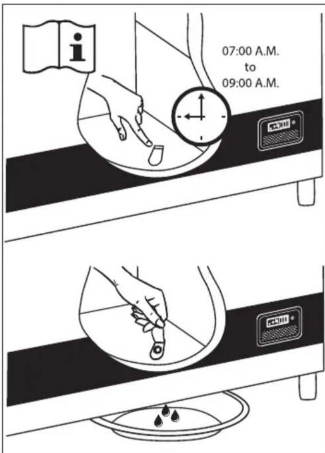
Fig. 16
Troubleshooting
| Fault Possible cause Remedy | ||
| Compressor is not running | Be patient, it is most likely that the compressor will start within a few minutes. | If this is not the case, check the following:- Check that power is connected- Check the fuse and replace it if necessary.- If the above is OK, call technical supervisor. |
| Compressor is running, and the temperature is too high | The ventilation grille is blocked.The lid is not closed properly.The temperature in the room in which the appliance is installed is too high. | Ensure unhindered air circulation.Ensure that the lid is closed properly.Shield the appliance against direct sun light and ensure more ventilation to the room. |
| No temperature is displayed | The micro processor control unit is brokenPower not connected | Change the micro processor control unit.Check power outlet - Check power plug is connected. |
Warranty, spare parts, and service
Warranty disclaimer
Faults and damage caused directly or indirectly by incorrect operation, misuse, insufficient maintenance, incorrect installation, or incorrect mains connections. Fire, accident, lightning, voltage variation, or other electrical interference, including defective fuses or faults in mains installations, are not covered by the warranty.
Repairs performed by anyone other than approved service centers, and any other faults or damage that the manufacturer can substantiate are caused by reasons other than manufacturing or material faults, are not covered by the warranty.
Please note that changes to the construction of the appliance or changes to the component equipment of the appliance will invalidate the warranty and product liability, and the appliance cannot be used lawfully. The approval stated on the rating plate will also be invalidated.
Before calling for technical assistance, please check whether you are able to rectify the fault yourself. If your request for assistance is unwarranted, e.g., if the appliance has failed as a result of a blown fuse or incorrect operation, you will be charged the costs incurred by your call for technical assistance.
Spare parts
When ordering spare parts, please state the type, serial, and product numbers of your appliance. This information is given on the rating plate (Fig. 17). The rating plate contains various technical information, including type and serial numbers.
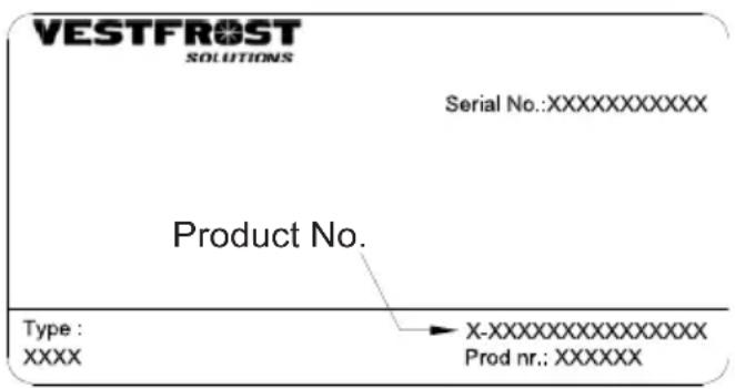
fig. 17
Disposal
Information for Users on Collection and Disposal of Old Equipment and used Batteries

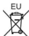
These symbols on the products, packaging, and/or accompanying documents mean that used electrical and electronic products and batteries should not be mixed with general household waste. For proper treatment, recovery and recycling of old products and used batteries, please take them to applicable collection points, in accordance with your national legislation and the Directives 2012/19/EU and 2006/66/EC.
By disposing of these products and batteries correctly, you will help to save valuable resources and prevent any potential negative effects on human health and the environment which could otherwise arise from inappropriate waste handling.
For more information about collection and recycling of old products and batteries, please contact your local municipality, your waste disposal service or the point of sale where you purchased the items.
Penalties may be applicable for incorrect disposal of this waste, in accordance with national legislation.
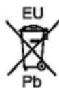
For business users in the European Union.
If you wish to discard electrical and electronic equipment, please contact your dealer or supplier for further information.
Information on Disposal in other Countries outside the European Union
These symbols are only valid in the European Union. If you wish to discard this product, please contact your local authorities or dealer and ask for the correct method of disposal.
Note for the battery symbol:
This symbol might be used in combination with a chemical symbol. In this case it complies with the requirement set by the Directive for the chemical involved.
Warning
WARNING:
fig. 2
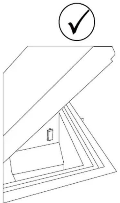
fig. 3 fig. 4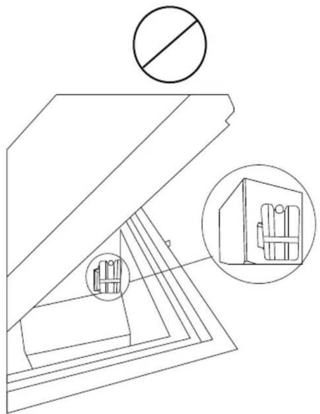
fig. 5
Fridge-tag Support
fig. 6
Location
fig. 8
fig. 9 fig. 10
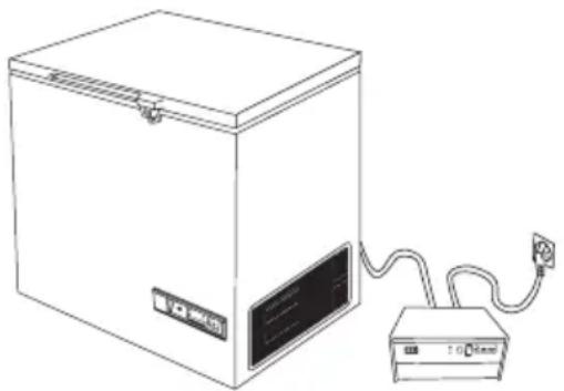
fig. 13
fig. 14
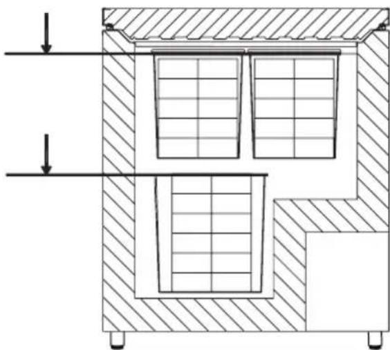
fig. 15
fig. 16
Troubleshooting
WARNING:
fig. 2
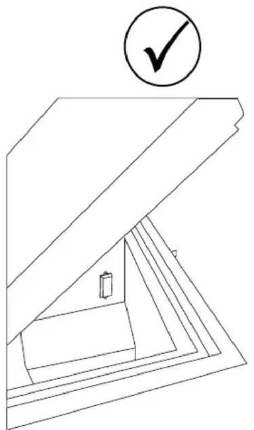
fig. 3
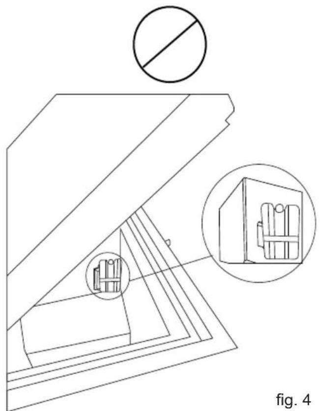
fig. 5
Fridge-tag
Support
General information
Location
fig. 8
fig. 9 fig. 10
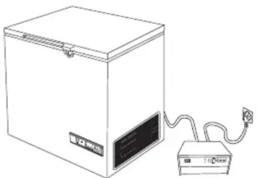
fig. 14
fig. 16
fig. 2

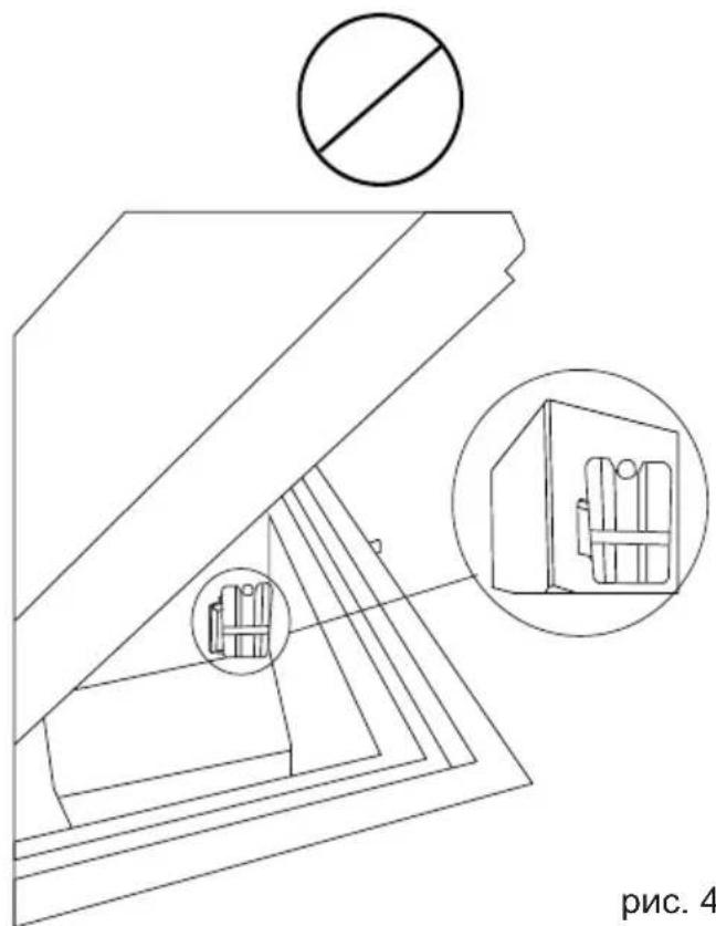
fig. 4 fig. 3
fig. 5
Fridge-tag
Support
General information
General information
Fig. 6
Choosing the location
Fig. 8
Fig. 13
Loading the device
Loading the vaccine
Fig. 14
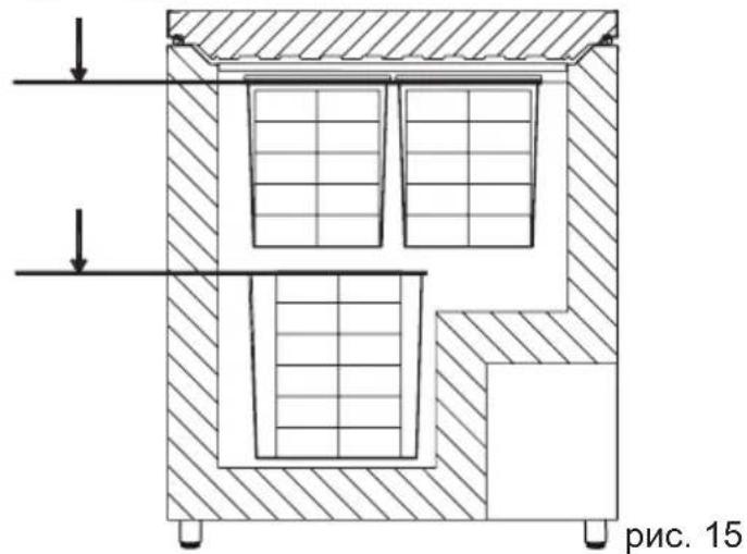
Fig. 16
Fig. 2
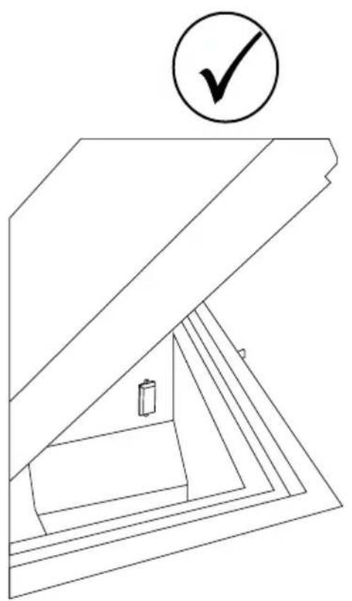
Fig. 3, Fig. 4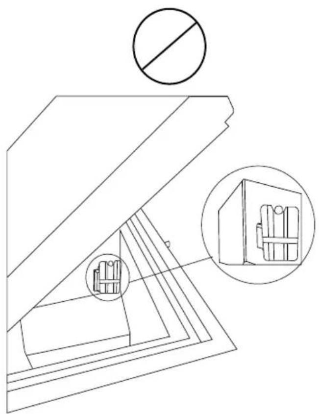
Placing the temperature display
Fig. 5
Fridge-tag Support
General information
Fig. 6
Position
Figure 8
Voltage stabilizer
Figures 9 and 10
Operation and function
Green light
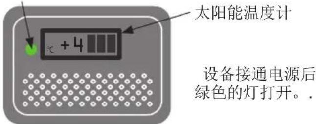
Figure 13
Loading equipment
Loading vaccines
Figure 14
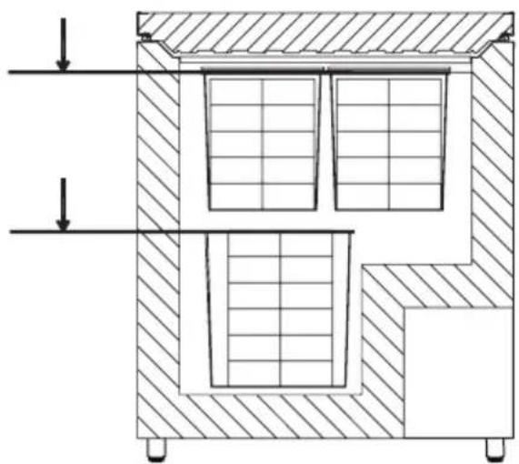
Figure 15
Maintenance and cleaning
Daily maintenance:
Figure 16
Troubleshooting
Continue with the following procedure:
Important!
Operation and function
Control key
General information
Location
Fridge-tag mode?
Fridge-tag
Support
Very important for the forest!
Warning:

ILR Refrigerator Model VLS 204A/304A/354A/404A/504A A AC
- WARNING
- CONTENTS
- GET TO KNOW YOUR REFRIGERATOR
- HIGHLY IMPORTANT
- PLACING THE FRIDGE-TAG ®
- EXTERNAL SENSOR
- GENERAL INFORMATION
- POWER SUPPLY
- TECHNICAL DATA
- UNPACKING
- ADJUSTABLE FEET
- LOCATION
- VOLTAGE STABILIZERS
- ELECTRICAL CONNECTION
- INFORMATION REGARDING VOLTAGE, CURRENT OR POWER IS GIVEN ON THE RATING PLATE
- OPERATION AND FUNCTION
- STARTING PROCEDURE
- TEMPERATURE CONTROL
- COOL DOWN OF THE APPLIANCE
- CONTROLLER
- LOADING THE APPLIANCE
- LOADING VACCINES
- VACCINE STORAGE
- MAINTENANCE AND CLEANING
- DAILY MAINTENANCE
- WEEKLY MAINTENANCE
- MONTHLY MAINTENANCE
- YEARLY MAINTENANCE
- CLEANING
- CONDENSATION WATER DRAINAGE
- IMPORTANT
- TROUBLESHOOTING
- WARRANTY, SPARE PARTS, AND SERVICE
- WARRANTY DISCLAIMER
- SPARE PARTS
- DISPOSAL
- INFORMATION ON DISPOSAL IN OTHER COUNTRIES OUTSIDE THE EUROPEAN UNION
- NOTE FOR THE BATTERY SYMBOL
- CHOOSING THE LOCATION
- LOADING THE DEVICE
- LOADING THE VACCINE
- PLACING THE TEMPERATURE DISPLAY
- POSITION
- VOLTAGE STABILIZER
- LOADING EQUIPMENT
- CONTROL KEY
- FRIDGE-TAG MODE
Brand : VESTFROST
Model : VLS 504A AC
Category : Refrigerator