
Motion Sensor - Alarm system eufy - Free user manual and instructions
Find the device manual for free Motion Sensor eufy in PDF.
| Product type | Wireless motion detector |
| Brand | Eufy |
| Model | Motion Sensor (TB910) |
| Power | 1 CR123A battery |
| Detection range (default) | 6 to 8 meters |
| Recommended tilt angle | 20° downward (without pets), 10° downward (with pets) |
| Recommended mounting height | 2 m to 2.5 m |
| Frequency range | 866-866.8 MHz (EU) / 920-920.8 MHz (US) |
| Operating temperature | -10°C to 40°C |
| Storage temperature | -20°C to 60°C |
| Usage | Indoor |
| Main functions | Motion detection, pairing with HomeBase, test mode, adjustable sensitivity |
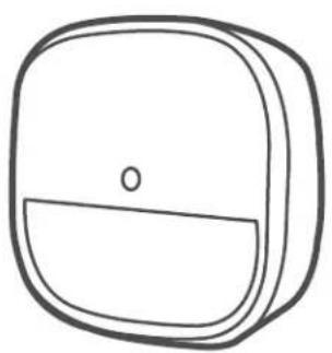
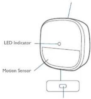
| LED indicator | Solid blue (pairing successful), blinking blue (waiting for connection or movement), blinking red (movement without HomeBase or low battery) |
| Mounting | On wall with screws or included 3M adhesive pad |
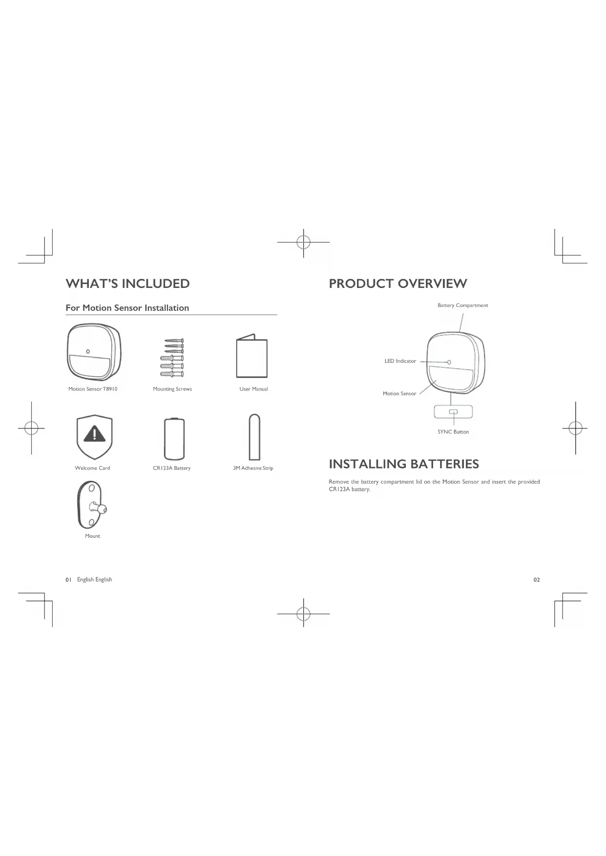
| Box contents | Motion detector, bracket, mounting screws, 3M adhesive pad, CR123A battery, welcome card |
| Maintenance | Clean with a soft, dry cloth |
| Battery replacement | Replace the CR123A battery when the indicator blinks red |
| Certifications | FCC ID: 2AOKB-T8910, IC: 23451-T8910 |
| RF safety distance | Keep a distance of 20 cm from the body |
| Compatibility | eufy Security HomeBase |
Frequently Asked Questions - Motion Sensor eufy
User questions about Motion Sensor eufy
0 question about this device. Answer the ones you know or ask your own.
Ask a new question about this device
Download the instructions for your Alarm system in PDF format for free! Find your manual Motion Sensor - eufy and take your electronic device back in hand. On this page are published all the documents necessary for the use of your device. Motion Sensor by eufy.
USER MANUAL Motion Sensor eufy
Anker Innovations Limited. All rights reserved.eufy Security and eufy Security Logo are trademarks of Anker Innovations Limited, registered in the United States and other countries. All other trademarks are the property of their respective owners.
Model: T8910
51005002527 V01
English
Deutsch
Espanol
Français
Italiano
Nederlandsls
Portugues
4.1.9
TABLE OF
CONTENTS
What's Included
01 07
Using the Motion Sensor
Product Overview
02 08
Replacing the Battery
Installing Batteries
02 08
Specifications
Adding Motion Sensor To
03 09
Notice
Mounding the Motion Sensor
04
WHAT'S INCLUDED
For Motion Sensor Installation
Motion Sensor T8910
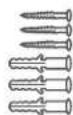
Mounting Screws

User Manual


Welcome Card
CR123A Battery

3M Adhesive Strip
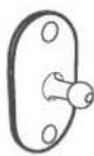
Mount
01
English English
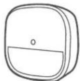
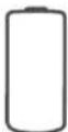
PRODUCT OVERVIEW
Battery Compartment
SYNC Button
INSTALLING BATTERIES
Remove the battery compartment lid on the Motion Sensor and insert the provided CR123A battery.
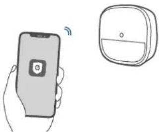
ADDING MOTION SENSOR TO YOUR SYSTEM
Note: Make sure you've completed the setup of your eufy Security HomeBase.
Follow the onscreen instructions on the Eufy Security app to add your motion sensor.
- Choose Add Device, then select Motion Sensor to add it to your system.
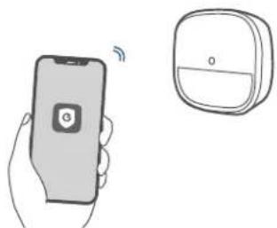
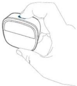
- Press and hold the SYNC button for 2 seconds until the LED indicator blinks blue. The Motion Sensor is waiting to pair.
- The LED indicator turns solid blue to indicate the pairing is successful.
| LED Status Description | |
| Blinking blue continuously | Waiting to connect |
| Solid blue for 5s Paired successfully | |
| Off Failed to connect to the HomeBase |
Note: The LED indicator, device name and timer can be customized on the eufy Security app.
MOUNTING THE MOTION SENSOR
Find a Location for Mounting
The motion sensor can be installed on a wall. To get optimal detection coverage, consider the following factors before mounting the motion sensor:
Determine the area of detection and ensure there is an unobstructed field of view
Determine the height and tilt angle
- Avoid direct sources of heat or sunshine, curtains, plants, or pets.
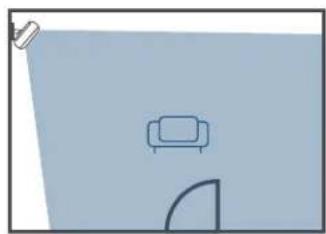
Ideally, the motion sensor should be installed on a wall facing the door through which people are likely to enter. We recommend placing the motion sensor close to a corner to get the optimal detection coverage.
You can also install the motion sensor in your garage, dining room, or basement.
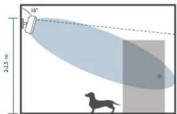
Height and Tilt Angle
The motion sensor should be mounted 2m / 64 ft to 2.5m / 8% ft above the floor with a tilt angle of preferably 20^ downwards. If you have a large pet weighing more than 50 lb, change to a 10^ downwards tilt.
With Pets
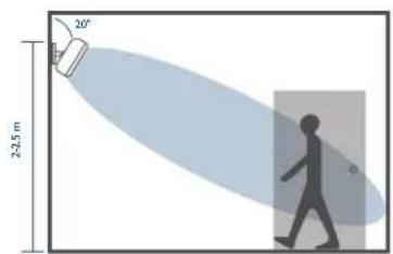
No Pets
To better detect the area where people may break in, rotate the motion sensor horizontally up to 30^ .
Sensitivity
The sensitivity can be adjusted based on the room size. The default setting is medium sensitivity.
Mount the Motion Sensor
- There are two methods of mounting the motion sensor at the selected location:
Use the 3M adhesive strip:
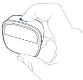
① Snap the adjustable wall mount onto the motion sensor base.
② Stick the adhesive strip on the back of the sensor, remove the film, and stick the motion sensor on the wall.
③ Rotate the motion sensor to adjust the detection coverage. - Use the provided screws:
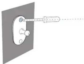
① Place the mount against the wall and use a pencil to mark the desired location for mounting.
② Drill holes at each marking. No need to drill a pilot hole in the wooden walls.
③ Insert anchors into the holes, and fix the mount onto the wall with the provided screws. No anchors are needed on wooden walls.
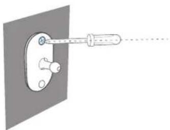
④ Clip the motion sensor back onto the mount.
Rotate the motion sensor to adjust the detection coverage.
USING THE MOTION SENSOR
After the motion sensor is installed, the alarm will be triggered once movement is detected within the motion sensor's coverage area.
When the motion sensor is working, its LED indicator shows as below:
| LED Status Description | |
| Blinking blue Movement detected while the HomeBase is connected | |
| Blinking red Movement detected while the HomeBase is not connected |
When the motion sensor is in the test mode, the LED indicator shows as below:
| LED Status Description | |
| Solid red Enter the test mode | e successfully |
| Blinking red for 1 second | Movement detected when the motion sensor is in the test mode. |
| Off Failed to enter the test mode | |
07 English English
REPLACING THE BATTERY
When the motion sensor's battery is low, the LED indicator shows as below. ou should replace the battery to keep the motion sensor working.
| LED Status Description | |
| Blinking blue Movement detected while the HomeBase is connected | |
| Blinking red Movement detected while the HomeBase is not connected |
SPECIFICATIONS
Battery: I×CR123A battery
Operating Temperature: -10°C - 40°C /14°F - 104°F
Storage Temperature: -20°C - 60°C / -4°F - 140°F
NOTICE
FCC Statement
This device complies with Part 15 of the FCC Rules. Operation is subject to the following two conditions: (1) this device may not cause harmful interference, and (2) this device must accept any interference received, including interference that may cause undesired operation.
Warning: Changes or modifications not expressly approved by the party responsible for compliance could void the user's authority to operate the equipment.
Note: This equipment has been tested and found to comply with the limits for a Class B digital device, pursuant to Part 15 of the FCC Rules. These limits are designed to provide reasonable protection against harmful interference in a residential installation.
This equipment generates uses and can radiate radio frequency energy and, if not installed and used in accordance with the instructions, may cause harmful interference to radio communications. However, there is no guarantee that interference will not occur in a particular installation. If this equipment does cause harmful interference to radio or television reception, which can be determined by turning the equipment off and on, the user is encouraged to try to correct the interference by one or more of the following measures: (1) Reorient or relocate the receiving antenna. (2) Increase the separation between the equipment and receiver. (3) Connect the equipment into an outlet on a circuit different from that to which the receiver is connected. (4) Consult the dealer or an experienced radio/TV technician for help.
FCC Radio Frequency Exposure Statement
The device has been evaluated to meet general RF exposure requirements. The device can be used in fixed / mobile exposure condition. The min separation distance is 20cm Notice: Shielded cables
All connections to other computing devices must be made using shielded cables to maintain compliance with FCC regulations.
The following importer is the responsible party.
Company Name: POWER MOBILE LIFE, LLC
Address: 400 108th Ave NE Ste 400, Bellevue, WA 98004-5541
Telephone: I-800-988-7973

This product complies with the radio interference requirements of the European Community.
Declaration of Conformity
Hereby, Anker Innovations Limited declares that this device is in compliance with the essential requirements and other relevant provisions of Directive 2014/53/EU. For the declaration of conformity, visit www.euflife.com.
Do not use the Device in the environment at too high or too low temperature, never expose the Device under strong sunshine or too wet environment.
The suitable temperature for the product and accessories is -10^ - 40^
RF exposure Information: The Maximum Permissible Exposure (MPE) level has been calculated based on a distance of d = 20cm between the device and the human body. To maintain compliance with RF exposure requirement, use product that maintain a 20cm distance between the device and the human body.
CAUTION RISK OF EXPLOSION IF BATTERY IS REPLACED BY AN INCORRECT TYPE. DISPOSE OF USED BATTERIES ACCORDING TO THE INSTRUCTIONS SUB-IG Frequency range: 866-866.8MHz (for EU) ; 920-920.8MHz (for US) Max Output Power: 6.496dBm (ERIP)
Anker Technology UK) Ltd Suite B, Fairgate House, 205 Kings Road, Tyseley, Birmingham, B11 2AA, United Kingdom

This product is designed and manufactured with high quality materials and components, which can be recycled and reused.

This symbol means the product must not be discarded as household waste, and should be delivered to an appropriate collection facility for recycling. Proper disposal and recycling helps protect natural resources, human health and the environment. For more information on disposal and recycling of this product, contact your local municipality, disposal service, or the shop where you bought this product.
IC Statement
This device complies with Industry Canada licence-exempt RSS standard(s). Operation is subject to the following two conditions:
(1) this device may not cause interference, and
(2) this device must accept any interference, including interference that may cause undesired operation of the device."
Le present appeareil est conforme aux CNR d'Industrie Canada applicables aux
This Class B digital apparatus complies with Canadian ICES-003.
When using the product, maintain a distance of 20cm from the body to ensure compliance with RF exposure requirements.
Anker Innovations Limited
Room 1318-19, Hollywood Plaza, 610 Nathan Road, Mongkok, Kowloon, Hong Kong
INHALTS-VERZEICHNIS
Im Lieferumfang
13 16
Instalar As Bacterias
5965
Substitur A Bacteria
aill CR123A aJai Jai Jai Jai Jai Jai Jai Jai Jai Jai Jai Jai Jai Jai Jai
yjll j jll jai jai jai
67
68
aaii
y eufy Security HomeBase 1
y y 1
LED 2
69
y
| LED | |
eufy Security jj pdd LED
45
#
d j 1 1 1 1 1 1 1 1 1 1 1 1 1 1 1 1 1 1 1
S OBC = S COD + S BOC - S BOC
as jell jieiu jieu 15ji
iiaai 1
45 jaiy 1jaiy 1jaiy 1jaiy 1jaiy 1jaiy 1jaiy 1jaiy
aai ai 15
(3)
:
gaiieiae gaii jaiipaiai, jaiilai 1
2
72
Aa 1 Aaa ydl gdl pduu dlae cuiill sll Cg Caiid
i 1
4
LILSYI gla hai jai 45 jaiy jia yj
Motion Sensor
aaiiie iiai jai 1 aaii iaii jaiy jaiy aiai yaiy
a5^3 + a6^3 + a_7^3 = 26^3
yLs yolled LED 1y
| LED jujia killa | wongjia |
| jujia 3,2,1 HomeBase jujia | jiujia 4S jiujia 5S ji |
| jujia 3,2,1 HomeBase jujia | jiujia 4S jiujia 5S ji |
yLLED Jia jao yaiy jao as aas
| LED jujia lila kajil |
| jujia lila jujia lila jujia lila jujia lila jujia lila jujia lila jujia lila jujia lila jujia lila jujia lila jujia lila jujia lila jujia lila jujia lila jujia lila jujia lila jujia lila jujia lila jujia lila jujia lila jujia lila |
73
iJ
LLED
aJ 1
| LED jujia jujia |
| jujia jujia jujia jujia jujia jujia jujia jujia jujia jujia jujia jujia jujia jujia jujia jujia jujia jujia jujia jujia jujia jujia jujia jujia jujia jujia jujia jujia jujia jujia jujia jujia jujia jujia juhui jujia jujia jujia jujia jujia jujia jujia jujia jujia jujia jujia jujia jujia jujia jujia jujia jujia jujia jujia jujia jujia jujia jujia jujia jujia jujia jujia jujia jujia jujia jujia jujia jujia |
Cleal gai
CR123A×1
920.8~920;()SUB-1G:866~866.8
()
104 14/24 40-10
140-4/26 60-20j
74


- TABLE OF
- CONTENTS
- WHAT'S INCLUDED
- PRODUCT OVERVIEW
- INSTALLING BATTERIES
- ADDING MOTION SENSOR TO YOUR SYSTEM
- MOUNTING THE MOTION SENSOR
- Find a Location for Mounting
- Height and Tilt Angle
- Sensitivity
- Mount the Motion Sensor
- USING THE MOTION SENSOR
- REPLACING THE BATTERY
- SPECIFICATIONS
- NOTICE
- FCC Statement
- FCC Radio Frequency Exposure Statement
- Declaration of Conformity
- IC Statement
- INHALTS-VERZEICHNIS
- aaii
- 45
- #
- Motion Sensor
- iJ
- Cleal gai
Brand : eufy
Model : Motion Sensor
Category : Alarm system