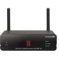
X1TX8 - Hi-fi system Russound - Free user manual and instructions
Find the device manual for free X1TX8 Russound in PDF.


| Product type | Amplified multiroom hi-fi system |
| Brand | Russound |
| Model | X1TX8 |
| Dimensions (W x H x D) | Approx. 430 x 88 x 250 mm |
| Weight | Approx. 4.5 kg |
| Power supply | 120 V AC, 50/60 Hz |
| Power consumption | 150 W (max) |
| Output power | 8 x 20 W RMS into 8 ohms |
| Audio inputs | 8 stereo line inputs (RCA) |
| Speaker outputs | 8 zones, screw terminals |
| Speaker impedance | 6 to 8 ohms |
| Main features | Multiroom audio distribution, built-in amplification, remote control |
| Care and cleaning | Wipe with a soft, dry cloth. Do not use solvents. |
| Safety | Do not expose to water, moisture, excessive heat. Unplug during storms or prolonged non-use. |
| Spare parts and repairability | Repair by qualified professional only. No user-serviceable parts. |
| General information | Compliant with FCC and IC standards. Indoor use only. |
Frequently Asked Questions - X1TX8 Russound
User questions about X1TX8 Russound
0 question about this device. Answer the ones you know or ask your own.
Ask a new question about this device
Download the instructions for your Hi-fi system in PDF format for free! Find your manual X1TX8 - Russound and take your electronic device back in hand. On this page are published all the documents necessary for the use of your device. X1TX8 by Russound.
USER MANUAL X1TX8 Russound
X1-TX8 Multi-channel Wireless Transmitter
X1-RX2 Wireless Receiver
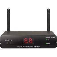
X1-RX220 Wireless Receiver Amplifier
Installation Manual

SAFETY INSTRUCTIONS
ATTENTION:
RISQUE DE CHOC ELECTRIQUE NE PAS OUVRIR.

WARNING: TO REDUCE THE RISK OF FIRE OR ELECTRIC SHOCK, DO NOT EXPOSE THIS APPLIANCE TO RAIN OR MOISTURE.
ATTENTION: AFIN DE RÉDUIRE LES RISQUES D'INCENDUE OU DE CHOC ÉLECTRIQUE, NE PAS EXPOSER CET APPAREIL À LA PLUIE OU.

CAUTION: TO REDUCE THE RISK OF ELECTRIC SHOCK, DO NOT REMOVE THE COVER. NO USER-SERVICEABLE PARTS INSIDE. REFER SERVICING TO QUALIFIED SERVICE PERSONNEL. ATTENTION: AFIN DE REDUIRE LE RISQUE DE CHOC ÉLECTRIQUE, NE PAS RETIRER LE CAPOT. AUCUNE PIECE À L'INTERIEUR. CONFIER L'ENTRETIEN DE PERSONNEL QUALIFIÉ.

The lightning flash with arrowhead symbol, within an equilateral triangle, is intended to alert the user to the presence of uninsulated dangerous voltage within the product's enclosure that may be of sufficient magnitude to constitute a risk of electric shock to persons.

The exclamation point within an equilateral triangle is intended to alert the user to the presence of important operating and maintenance (servicing) instructions in the literature accompanying the appliance.
Safety Instructions
- Read Instructions - All the safety and operating instructions should be read before the appliance is operated.
- Cleaning - The appliance should be cleaned only as recommended by the manufacturer. From time to time you should wipe off the front and side panels and the cabinet with a soft cloth. Do not use rough material, thinners, alcohol or other chemical solvents or cloths since this may damage the finish or remove the panel lettering.
- Ventilation - The appliance should be situated so that its location or position does not interfere with its proper ventilation. For example, the appliance should not be situated on a bed, sofa, rug, or similar surface that may block the ventilation openings, or placed in a built-in installation, such as a bookcase or cabinet that may impede the flow of air through the ventilation openings. Place the unit in a well-ventilated location, leaving at least 2 inches (5 cm) of clearance on all sides, top and rear of unit for air flow. If ventilation is blocked, the unit may overheat and malfunction.
This device complies with Part 15 of the FCC Rules / Industry Canada licence-exempt RSS standard(s). Operation is subject to the following two conditions: (1) this device may not cause harmful interference, and (2) this device must accept any interference received, including interference that may cause undesired operation.
Changes or modifications not expressly approved by the party responsible for compliance could void the user's authority to operate the equipment.
This equipment has been tested and found to comply with the limits for a Class B digital device, pursuant to part 15 of the FCC Rules. These limits aredesigned to provide reasonable protection against harmful interference in a residential installation. This equipment generates uses and can radiate radio frequency energy and, if not installed and used in accordance with the instructions, may cause harmful interference to radio communications. However, there is no guarantee that interference will not occur in a particular installation. If this equipment does cause harmful interference to radio or television reception, which can be determined by turning the equipment off and on, the user is encouraged to try to correct the interference by one or more of the following measures:
Reorient or relocate the receiving antenna.
-
Increase the separation between the equipment and receiver.
-
Connect the equipment into an outlet on a circuit different from that to which the receiver is connected.
-
Consult the dealer or an experienced radio/TV technician for help.
Under Industry Canada regulations, this radio transmitter may only operate using an antenna of a type and maximum (or lesser) gain approved for the transmitter by Industry Canada. To reduce potential radio interference to other users, the antenna type and its gain should be so chosen that the equivalent isotropically radiated power (e.i.r.p.) is not more than that necessary for successful communication.
To satisfy FCC / IC RF exposure requirements, a separation distance of 20~cm or more should be maintained between the antenna of this device and persons during device operation.
To ensure compliance, operations at closer than this distance is not recommended.
This radio transmitter (identify the device by certification number, or model number if Category II) has been approved by Industry Canada to operate with the antenna types listed below with the maximum permissible gain and required antenna impedance for each antenna type indicated. Antenna types not included in this list, having a gain greater than the maximum gain indicated for that type, are strictly prohibited for use with this device.
Gain of antenna: 3.0dBi max.
Type of antenna: Omni-directional
Impedance of antenna: 50ohm
This device complies with RSS-310 of Industry Canada. Operation is subject to the condition that this device does not cause harmful interference.
Contains of FCC ID: XCO-HSDWAM83 and IC: 7756A-HSDWAM83.


TABLE OF CONTENTS
Product Operation 6-7
X1-TX8 Front, Back Panel 8
X1-RX2 Front, Back Panel 9
X1-RX220 Front, Back Panel 10
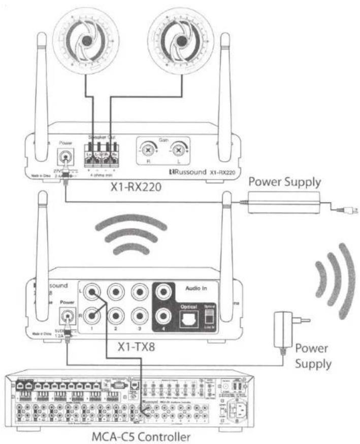
Connection Diagram 11
Installation Overview 12
Features 13
Technical specifications 13
PRODUCT OPERATION
Thank you for choosing the Russound XStream X1 family of products, the new performance standard in wireless audio.
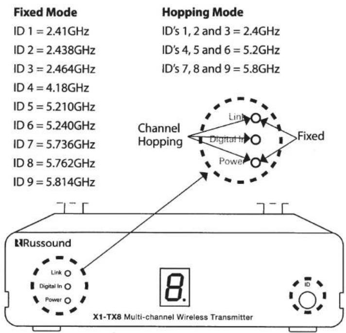
The X1 products operate over three bands, 2.4GHz, 5.2GHz and 5.8GHz and feature Channel Hopping Mode or Fixed Channel Mode.
Although the X1 product uses bands that are in the Wi-Fi spectrum, the proprietary digital signal transmitted is not used in the Wi-Fi system. This provides a more reliable connection with very low latency between the original source signal and the output receiver, eliminating any echo effect.
The 2.4GHz operates better through walls than the higher frequency. However, this band is widely used in many systems including Wi-Fi. If the band is crowded interference may occur. The 5.2GHz and 5.8GHz bands do not go through walls at the same distance as the lower bands. However, they will have less interference.
Channel Hopping or Fixed Channel Mode
The channel hopping technology will combat crowded spaces by searching for the cleanest channel within the band. Determining the modes and band used is a question of application, distance requirements and may require some trial.
Depending on the amount of RF signals in your installation you may choose to select between Channel Hopping or Fixed Channel mode.
To select between these modes, press and hold the ID button on the front of the X1-TX8 while applying power, look for 2 LED's or 3 LED's illuminated on the front of the unit. 2 LED's represents Fixed Mode, 3 LED's represents hopping mode. To change the mode press the ID button on the X1-TX8 while applying power, verify the selection with the LED illumination
ID. Sets the channel and the Band
Channels are determined by the inputs 1-4 on the rear panel of the X1-TX8 and selecting the corresponding channel on the X1-RX2 or X1-RX220 receivers. Source input 1 on the X1-TX8 is Channel 1 on the receiver, source input 2 is Channel 2, etc.
Antenna placement
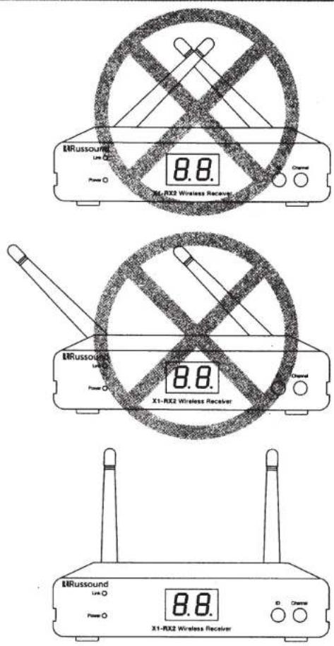
For best performance, locate the transmitter and receiver in an area that is not surrounded by metal or other equipment that may interfere with transmission. Placement should be carefully thought out. Transmitter and receiver antennas should be in vertical and parallel position for maximum performance - see illustration.
X1-TX8 FRONT, BACK PANEL
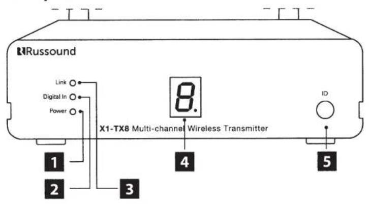
Front panel
1 Power
Digital In Confirms digital audio in
3 Link Confirms connection to receiver X1-RX2 or X1-RX220
4 8. ID Number
5 ID Sets ID to match receiver X1-RX2 or X1-RX220

Back panel
1 Power Plug Inlet
2 Power Supply 5VDC1.2A
Channels 1 thru 4
4 Audio In Audio inputs: 1-3 Line level 4 Line in or optical
5 Antenna
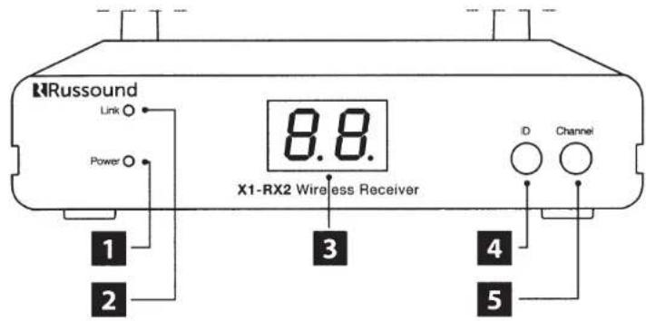
Front panel
1 Power
2 Link Confirms connection to transmitter X1-TX8
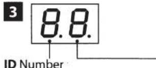
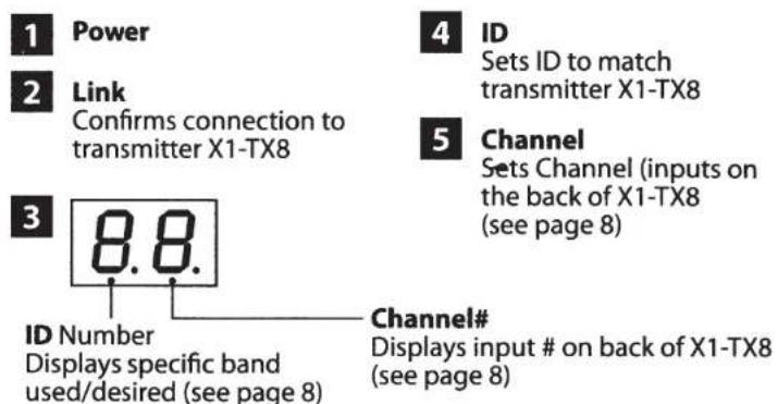
Displays specific band used/desired (see page 8)
4 ID
Sets ID to match transmitter X1-TX8
5 Channel
Sets Channel (inputs on the back of X1-TX8 see page 8
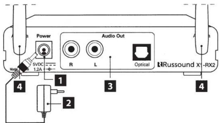
Back panel
1 Power Plug Inlet
2 Power Supply 5VDC1.2A
3 Audio Out
Audio output RCA and optical connectors
4 Antenna
X1-RX220 FRONT, BACK PANEL
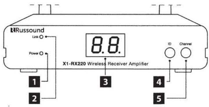
Front panel
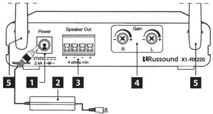
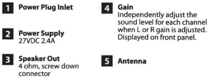
Back panel

INSTALLATION OVERVIEW
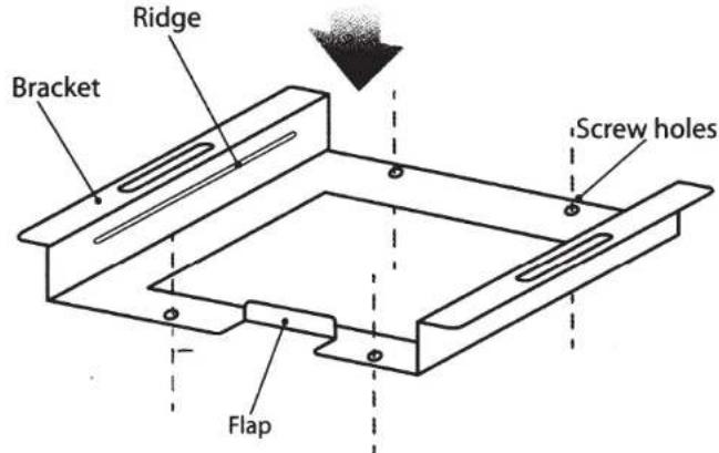
The X1 products can be placed on any flat surface or securely mounted in place with the included bracket and screws.
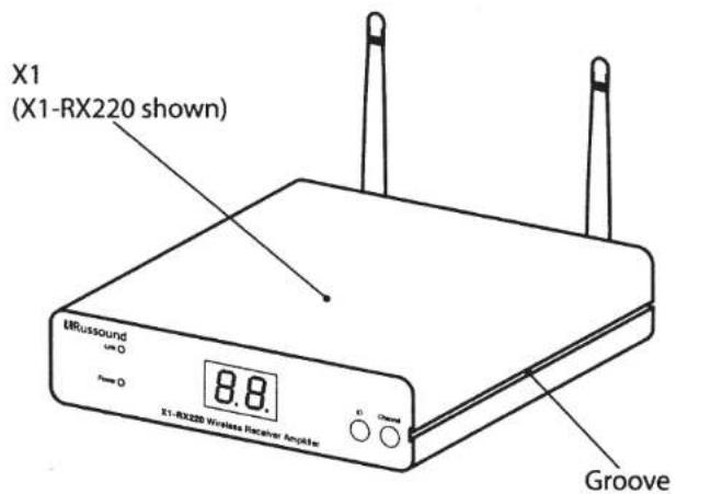
To mount, simply fasten the bracket to a desired location with the screws and snap the X1 into place with the front of the unit against the flap. Make sure the bracket ridge is in line with groove on the sides of the X1.
Note: For wall mount installations make sure that the bracket flap is oriented on the bottom to prevent the X1 from sliding downward.
FEATURES
TECHNICAL SPECIFICATIONS
X1-TX8
- Simultaneously transmits 4 separate wireless audio zones, sources
Wireless Signal Range 30M (100ft) via proprietary digital RF
Transmits signals to RX220 or RX21 - Hides easily, small footprint
X1-RX2
- Receives audio signals from TX8 transmitter
- Outputs line level or optical audio signals from TX8
- Wireless Signal Range 30m (100ft) via proprietary digital RF
Requires TX8 transmitter - Hides easily, small footprint
X1-RX220
- Receives audio signals from TX8 transmitter
Built in Amplifier 2 x 20 WRMS into 4 ohm - Individual Gain Adjustments
- Wireless Signal Range 30M (100ft) from TX8 via proprietary digital RF
Requires TX8 transmitter - Hides easily, small footprint
X1-TX8
Digital Audio Inputs: RCA, Optical
Power Requirements: 5VDC 1.2A (must use supplied power supply)
Dimensions (without antennas): 3.625"W x 4.75"D x 1.5"H (92 x 121 x 38mm)
Weight: 0.62 lbs. (0.28 kg)
X1-RX2
Digital Audio Outputs: RCA, Optical
Power Requirements: SVDC 1.2A (must use supplied power supply)
Dimensions (without antennas): 3.625"W x 4.75"D x 1.1875"H (92 x 121 x 30mm)
Weight: 0.64 lbs. (0.29 kg)
X1-RX220
Digital Audio Outputs: 20W × 2,4 ohms min
Power Requirements: 27VDC 2.4A (must use supplied power supply)
Dimensions (without antennas): 5.125"W x 4.75"D x 1.1875"H (131 x 121 x 30mm)
Weight: 0.86 lbs. (0.39 kg)
RRussound
X1 Products
X1-TX8 Multi-channel Wireless Transmitter
X1-RX2 Wireless Receiver
X1-RX220 Wireless Receiver Amplifier
Installation Manual
©2013 Russound. All rights reserved.
All trademarks are the property of their respective owners.
Specifications are subject to change without notice.
Russound is not responsible for typographical errors or omissions.
Russound, Inc.
5 Forbes Road, Newmarket, NH 03857
tel 603.659.5170·fax 603.659.5388
email: tech@russound.com www.russound.com
28-1383 12.05.13, Rev.3
- SAFETY INSTRUCTIONS
- ATTENTION:
- TABLE OF CONTENTS
- PRODUCT OPERATION
- Channel Hopping or Fixed Channel Mode
- Sets the channel and the Band
- Antenna placement
- X1-TX8 FRONT, BACK PANEL
- Power
- ID
- Channel
- Power Plug Inlet
- Audio Out
- X1-RX220 FRONT, BACK PANEL
- INSTALLATION OVERVIEW
- FEATURES
- TECHNICAL SPECIFICATIONS
- X1-TX8
- X1-RX2
- X1-RX220
- RRussound
- X1 Products
- Installation Manual
Brand : Russound
Model : X1TX8
Category : Hi-fi system