
MER7700LZ - Cooker MAYTAG - Free user manual and instructions
Find the device manual for free MER7700LZ MAYTAG in PDF.
| Product Type | Freestanding Range |
| Brand | Maytag |
| Model | MER7700LZ |
| Width | 76.2 cm (30 in) |
| Depth | approx. 68.6 cm (27 in) |
| Height | 91.4 cm (36 in) with adjustable feet |
| Weight | approx. 82 kg (180 lb) |
| Power Supply | 250 V, 40 A or 50 A, single phase |
| Connection Type | Power cord or direct wiring (3 or 4 wires) |
| Cooktop Type | Coil elements (electric burners) |
| Number of Burners | 4 (varied sizes) |
| Oven Type | Conventional oven with self-cleaning cycle |
| Oven Capacity | Approx. 140 L (4.9 cu ft) |
| Oven Functions | Traditional baking, automatic cleaning, interior light |
| Oven Cleaning | Self-cleaning cycle (high temperature, wipe ash) |
| Surface Cleaning | Wipe with damp cloth, cooktop cleaner |
| Safety Device | Anti-tip bracket, door lock in self-clean |
| Drawer | Storage drawer or warming drawer depending on model |
| Replacement Parts | Accessories and spare parts available through Whirlpool |
| Repairability | Service by qualified technician recommended for repairs |
| Country of Manufacture | United States (likely) |
Frequently Asked Questions - MER7700LZ MAYTAG
User questions about MER7700LZ MAYTAG
0 question about this device. Answer the ones you know or ask your own.
Ask a new question about this device
Download the instructions for your Cooker in PDF format for free! Find your manual MER7700LZ - MAYTAG and take your electronic device back in hand. On this page are published all the documents necessary for the use of your device. MER7700LZ by MAYTAG.
USER MANUAL MER7700LZ MAYTAG
ELECTRIC FREESTANDING RANGE OWNER'S MANUAL
GUIDE D'UTILISATION DE LA CUISINIÈRE ÉLECTRIQUE AUTOPORTANTE
MANUAL DEL PROPIETARIO DE LA ESTUFA AUTONOMA ELECTRICA
Table of Contents/Table des matieres/Indice
RANGE SAFETY 2
Range Safety. 2
RANGE MAINTENANCE AND CARE....5
Self-Cleaning Cycle (on some
models) 5
General Cleaning. 5
INSTALLATION INSTRUCTIONS 7
REQUIREMENTS. 7
Tools and Parts 7
Location Requirements 7
Electrical Requirements - U.S.A.
Only. 8
Electrical Requirements - Canada
Only. 10
INSTALLATION 10
Unpack Range 10
Install Anti-Tip 11
Adjust Leveling Legs 12
Level Range 12
Electrical Connection USA Only.....13
Verify Anti-Tip Bracket Is Installed
and Engaged 18
Warming Printer or Premium
Storage Driver (on some models) ...
Storage Printer (on some models) ...
Oven Door 19
Complete Installation 20
Moving the Range 20
SECURITE DE LA CUISINIÈRE 21SEGURIDAD DE LA ESTUFA 42
Sécurité de la cuisine ................ 21 Range Safety. 42
ENTRETIEN ET REPARATION DE LA
CUISINIÈRE 24
Your safety and the safety of others are very important.
We have provided many important safety messages in this manual and on your appliance. Always read and obey all safety messages.

This is the safety alert symbol.
This symbol alerts you to potential hazards that can kill or hurt you and others.
All safety messages will follow the safety alert symbol and either the word "DANGER" or "WARNING." These words mean:
ADANGER
WARNING
All safety messages will tell you what the potential hazard is, tell you how to reduce the chance of injury, and tell you what can happen if the instructions are not followed.
You can be killed or seriously injured if you don't immediately follow instructions.
You can be killed or seriously injured if you don't follow instructions.
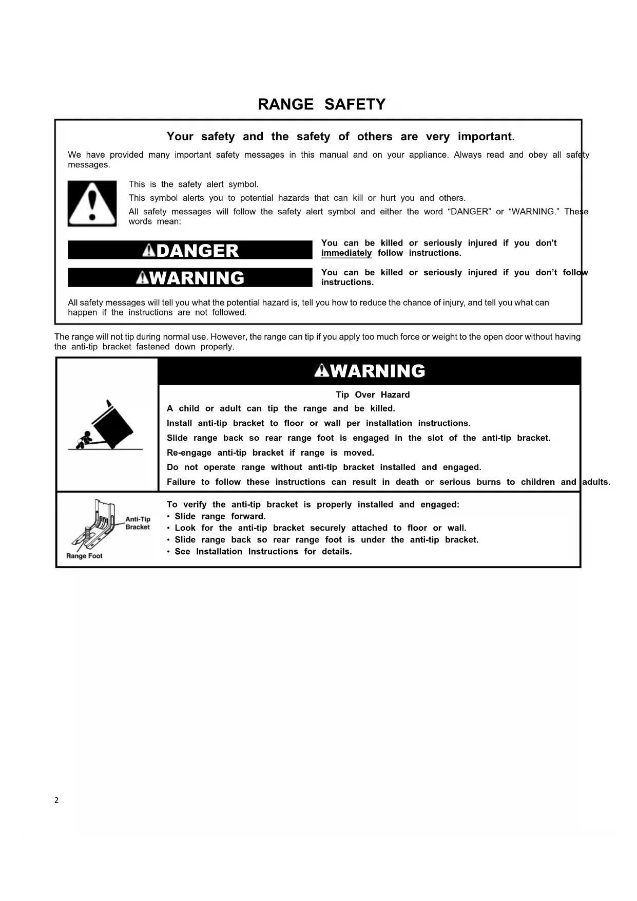
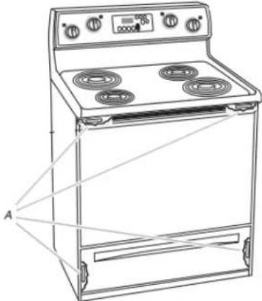
The range will not tip during normal use. However, the range can tip if you apply too much force or weight to the open door without having the anti-tip bracket fastened down properly.

WARNING
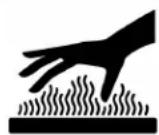
Tip Over Hazard
A child or adult can tip the range and be killed.
Install anti-tip bracket to floor or wall per installation instructions.
Slide range back so rear range foot is engaged in the slot of the anti-tip bracket.
Re-engage anti-tip bracket if range is moved.
Do not operate range without anti-tip bracket installed and engaged.
Failure to follow these instructions can result in death or serious burns to children and
adults.
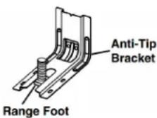
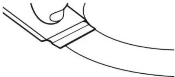
To verify the anti-tip bracket is properly installed and engaged:
- Slide range forward.
- Look for the anti-tip bracket securely attached to floor or wall.
- Slide range back so rear range foot is under the anti-tip bracket.
- See Installation Instructions for details.
IMPORTANT SAFETY INSTRUCTIONS
WARNING: To reduce the risk of fire, electric shock, or injury to persons when using the appliance, follow basic precautions, including the following:
WARNING: TO REDUCE THE RISK OF TIPPING OF THE RANGE, THE RANGE MUST BE SECURED BY PROPERLY INSTALLED ANTI-TIP DEVICES. TO CHECK IF THE DEVICES ARE INSTALLED PROPERLY, SLIDE RANGE FORWARD, LOOK FOR ANTI-TIP BRACKET SECURELY ATTACHED TO FLOOR OR WALL, AND SLIDE RANGE BACK SO REAR RANGE FOOT IS UNDER ANTI-TIP BRACKET.
WARNING: Danger of fire: Do not store items on the cooking surfaces. Never leave anything on the surface when unattended and not in use. Never place flammable plastic items on or near the surface.
CAUTION: Do not store items of interest to children in cabinets above an appliance or on the backguard of an appliance - children climbing on the appliance to reach items could be seriously injured.
-
Proper Installation - The appliance, when installed, must be electrically grounded in accordance with local codes, or the absence of local codes, with the National Electrical Code, ANSI/NFPA 70 or the Canadian Electrical Code, CSA C22.1-02. In Canada, the appliance must be electrically grounded in accordance with Canadian Electrical Code. Be sure your appliance is properly installed and grounded by a qualified technician.
-
Never Use Your Appliance for Warming or Heating the Room.
-
Do Not Leave Children Alone - Children should not be alone or unattended in area where appliance is in use. They should never be allowed to sit or stand on any the appliance.
Wear Proper Apparel - Loose-fitting or hanging garments should never be worn while using the appliance.
- User Servicing - Do not repair or replace any part of appliance unless specifically recommended in the manual. All other servicing should be referred to a qualified technician.
Storage in or on Appliance - Flammable materials should not be stored in an oven or near surface units.
This appliance is not intended for storage.
■ Do Not Use Water on Grease Fires - Smother fire or use dry chemical or foam-type extinguisher.
- Do not use replacement parts that have not been recommended by the manufacturer (e.g. parts made at home using a 3D printer).
Use Only Dry Potholders - Moist or damp potholders on surfaces may result in burns from steam. Do not let potholder touch hot heating elements. Do not use a too other bulky cloth.
-
DO NOT TOUCH SURFACE UNITS OR AREAS NEAR UNITS - Surface units may be hot even though they are dark in color. Areas near surface units may become hot enough to cause burns. During and after use, do not tie or let clothing or other flammable materials contact surface units or areas near units until they have had sufficient time to cool. Among these areas are the coil elements, the cooktop, and surfaces facing the cooktop.
-
Use Proper Pan Size - This appliance is equipped with on or more surface units of different size. Select utensils having flat bottoms large enough to cover the surface unit heating element. The use of undersized utensils will expose a portion of the heating element to direct contact and may result in ignition of clothing. Proper relationship of utensil to burner will also improve efficiency.
- Never Leave Surface Units Unattended at High Heat Settings - Boilover causes smoking and greasy spillovers that may ignite.
Make Sure Reflector Pans or Drip Bowls Are in Place - Absence of these pans or bowls during cooking may subject wiring or components underneath to damage.
Protective Liners - Do not use aluminum foil to line surface unit drip bowls or oven bottoms, except as suggested in the manual. Improper installation of these liners may result in a beisk of electric shock, or fire.
Glazed Cooking Utensils - Only certain types of glass, glass/ceramic, ceramic, earthenware, or other glazed utensils are suitable for range-top service without breaking due to the sudden change in temperature.
- Utensil Handles Should Be Turned Inward and Not Extend Over Adjacent Surface Units - To reduce the risk of burns, ignition of flammable materials, and spillage due to unintentional contact with the utensil, the handle of a utensil should be positioned so that it is turned inward, and does not extend over adjacent surface units.
■ Do Not Soak Removable Heating Elements - Heating padements should never be immersed in water.
■ Do Not Cook on Broken Cook-Top - If cook-top should break, cleaning solutions and spillovers may penetrate the broken cook-top and create a risk of electric shock. Contact the qualified technician immediately.
Clean Cooktop With Caution - If a wet sponge or cloth is used to wipe spills on a hot cooking area, be careful to avoid steam burn. Some cleaners can produce noxious fumes if applied to a hot surface.
Use Care When Opening Door - Let hot air or steam escape before removing or replacing food.
■Flame Not Heat Unopened Food Containers - Build-up of pressure may cause container to burst and result in injury.
- Keep Oven Vent Ducts Unobstructed.
- Placement of Oven Racks - Always place oven racks in desired location while oven is cool. If rack must be moved on white oven is hot, do not let potholder contact hot heating element in oven.
WEDOR NOT TOUCH HEATING ELEMENTS OR INTERIOR SURFACES OF OVEN - Heating elements may be hot even though they are dark in color. Interior surfaces of an areoven become hot enough to cause burns. During and after not use, do not touch, or let clothing or other flammable tourcterials contact heating elements or interior surfaces of faceoven until they have had sufficient time to cool. Other tirefaces of the appliance may become hot enough to cause burns - among these surfaces are oven vent openings and surfaces near these openings, oven doors, and windows of oven doors.
SAVE THESE INSTRUCTIONS
IMPORTANT SAFETY INSTRUCTIONS
WARNING: To reduce the risk of fire, electric shock, or injury to persons when using the appliance, follow basic precautions, including the following:
Care must be taken to prevent aluminum foil and meat Before Self-Cleaning the Oven - Remove broiler par and probes from contacting heating elements. other utensils.
For self-cleaning ranges -
CAUTION: DO NOT LEAVE FOOD OR COOKING UTENSILS, ETC., IN OVEN DURING THE PYROLYTIC SELF-CLEANING MODE OF OPERATION.
For units with ventilating hood -
Clean Ventilating Hoods Frequently - Grease should not be allowed to accumulate on hood or filter.
■ When flaming foods under the hood, turn the fan on.
■ Do Not Clean Door Gasket - The door gasket is essentialsmart enabled ranges and ovens
for a good seal. Care should be taken not to rub, damage or move the gasket. Remote operation - This appliance is configurable to allow remote operation at any time. Do not store any flammable Do Not Use Oven Cleaners - No commercial oven cleaner materials or temperature sensitive items inside, on top or oven liner protective coating of any kind should be used in or around any part of the oven.
Clean Only Parts Listed in Manual.
SAVE THESE INSTRUCTIONS
RANGE MAINTENANCE AND CARE
Self-Cleaning Cycle (on some models)
AWARNING
Burn Hazard
Do not touch the oven during the Self-Cleaning cycle.
Keep children away from the oven during Self-Cleaning cycle.
Failure to follow these instructions can result in burns.
Once the oven has completely cooled, remove ash with a damp cloth. To avoid breaking the glass, do not apply a cool damp to the inner door glass before it has completely cooled.
To stop the Self-Cleaning cycle at any time, press CANCEL or OFF/CANCEL. If the temperature is too high, the oven door will remain locked and "cool" and "locked" will be displayed.
When " shows in the display, the door of the oven cannot be opened. To avoid damage to the door, do not force the door when " is displayed.
Before self-cleaning, make sure the door is completely closed o the door will not lock and the Self-Cleaning cycle will not begin Once the cleaning temperature has been reached, the electronic control requires a 12 hour delay before another Self-Cleaning cycle can be started.
The oven light will not function during the Self-Cleaning cycle.
Electronic Oven Control with Adjustable Clean Time (on some models)
The Self-Cleaning cycle is time adjustable between 2 hours
30 minutes and 4 hours 30 minutes in 30 minute increments.
Suggested clean times are 2 hours 30 minutes for light soil and 4 hours 30 minutes for heavy soil. The last 30 minutes of the day for cooldown.
IMPORTANT: The health of some birds is extremely sensitive for cooldown.
the fumes given off during the Self-Cleaning cycle. ExposureIMBORTANT: When cooktop is in use, the Self-Cleaning cycle will be closed.
Keep the kitchen well-ventilated during the Self-Cleaning cycle to Self-Clean:
help get rid of heat, odors, and smoke.
Do not block the oven vent(s) during the Self-Cleaning cycle. must be able to move freely. Depending on your model, see Vent" or "Oven Vents" section in your Quick Start Guide. 3
Oven vent
Do not clean, rub, damage, or move the oven door gasket.
- Press CLEAN or SELF CLEAN.
- Press the Temp/Time "+" or "-" or "up" or "down" keypad.
See "Enter the desired Self-Cleaning cycle time." - Press START.
The oven door will automatically lock. The Door Locked and Clean indicator lights will be displayed. The time remaining is also be displayed.
- When the Self-Cleaning cycle is complete and the oven cool, the Door Locked and Clean indicator lights will turn off.
- When the oven is completely cooled, remove ash with a da cloth.
To exit the Self-Cleaning cycle before completed, press CANCEL or OFF/CANCEL. The door will unlock once the oven cools.
Prepare Range:
- Remove the broiler pan, grid, cookware and bakeware, all cooking utensils, oven racks, aluminum foil, and, on some models, the temperature probe from the oven.
Use a damp cloth to clean inside door edge and the 1.3.8 cm area around the inside oven cavity frame, being certain not to move or bend the gasket.
Wipe out any loose soil to reduce smoke and avoid dair. At high temperatures, foods react with porcelain. Staining, etching, pitting, or faint white spots can result. This will affect cooking performance. - Remove plastic items from the cooktop because they may melt.
Remove all items from the storage drawer.
How the Cycle Works
IMPORTANT: The heating and cooling of porcelain on steel oven may result in discoloring, loss of gloss, hairline cracks, popping sounds.
The Self-Cleaning cycle uses very high temperatures, burning to a powdery ash.
General Cleaning
9IMPORTANT: Before cleaning, make sure all controls are off and the oven and cooktop are cool. Always follow label instructions
cleaning products.
Soap, water, and a soft cloth or sponge are suggested first, u otherwise noted.
EXTERIOR PORCELAIN ENAMEL SURFACES (on some models)
Food spills containing acids, such as vinegar and tomato, should be cleaned as soon as the entire range is cool. These spills affect the finish.
Cleaning Method:
Glass cleaner, mild liquid cleaner, or nonabrasive scrubbing pad: Gently clean around the model/serial/rating plate because in smabbing may remove numbers.
■ Ashesh ^® Kitchen and Appliance Cleaner Part Number W10355010 (not included):
g sbe the Quick Start Guide for contact information.
STAINLESS STEEL (on some models)
NOTE: To avoid damage to stainless steel surfaces, do not use soap-filled scouring pads, abrasive cleaners, Cooktop Cleaner, steel-wool pads, gritty washcloths, or abrasive paper towels. Damage may occur to stainless steel surfaces, even with one-tin or limited use.
Cleaning Method:
Rub in direction of grain to avoid damaging.
■ Affresh® Stainless Steel Cleaner Part Number W10355016 (not included):
See the Quick Start Guide for contact information.
METALLIC PAINT (on some models)
Do not use abrasive cleaners, cleaners with bleach, rust removers, ammonia, or sodium hydroxide (lye) because paint surface may stain.
CERAMIC GLASS COOKTOP CLEANING Cleaning Method:
To avoid damaging the cooktop, do not use steel wool, abrasi powder cleansers, chlorine bleach, rust remover, or ammonia.
- Remove food/residue with the Cooktop Scaper.
- Polish with a clean, dry cloth or a clean, dry paper towel.

Repeat steps 1 through 3 as necessary for stubborn or burned-on stains.
The Complete Cooktop Cleaner Kit is available for order including the following:
Cooktop Scaper
^© Affresh ^® Cooktop Cleaner
Blue Cooktop Cleaning Pads
See the Quick Start Guide for ordering information.
COOKTOP CONTROLS
To avoid damage to the cooktop controls, do not use steel wO abrasive cleansers, or oven cleaner.
To avoid damage, do not soak knobs. When replacing knobs, make sure knobs are in the Off position.
On some models, do not remove seals under knobs.
Cleaning Method:
Soap and water: Pull knobs straight away from control panel remove.
For best results, use the Cooktop Scaper while the
cooktop is still warm but not hot to the touch. It is To avoid damage to the control panel, do not use abrasive recommended to wear an oven mitt while scraping thecleaners, steel-wool pads, gritty washcloths, or abrasive paper warm cooktop. towels.
Hold the Cooktop Scaper at approximately a 45^ and against the glass surface and scrape the residue. It necessary to apply pressure in order to remove the residue.
To avoid damage to the control panel, do not use abrasive gcleaners, steel-wool pads, gritty washcloths, or abrasive paper towels.
Glass cleaner and soft cloth or sponge: Apply glass cleaner soft cloth or sponge, not directly on panel.
Allow the cooktop to cool down completely before proceeding to Step 2.
- Apply a few dime-sized drops of Cooktop Cleaner to the affected areas.


CONTROL PANEL AND OVEN DOOR EXTERIOR
Cleaning Method:
■ Affresh® Kitchen and Appliance Cleaner Part Number: 10355010 (not included):
See the Quick Start Guide for contact information.
COIL ELEMENTS (on some models)
Cleaning Method:
Damp cloth: Make sure control knobs are OFF and elements are cool.
Do not clean or immerse in water. Soil will burn off when hot BURNER BOWLS (on some models)
Before removing or replacing coil elements and burner bowls, make sure they are cool and the control knobs are in the OP position.
Remove the coil element by pushing the edge of the coil elen toward the receptacle. Lift it enough to clear the burner bowl. the coil element straight away from the receptacle to remove. L
Rub affres Cleaner onto the cooktop surface with the out the burner bowl.
blue Cooktop Cleaning
Pad. Some pressure
e is
Cleaning Method:
Chrome burner bowls
frequently in warm, soapy water. (It is not recommended wash chrome bowls in a dishwasher.) A mild abrasive cleaner a plastic scrubber can be used to remove stubborn stains.
For heavily soiled bowls, place an ammonia-soaked paper towel on the stains and allow to soak for a short time, then gently with a plastic scrubber.
SURFACE UNDER COOKTOP (on some models)
The coil cooktop will lift up to provide easy access for cleaning beneath. Lift the cooktop by both front corners until the support locks into place.
Cleaning Method:
Glass cleaner, mild liquid cleaner or nonabrasive scrubbing pad.
■ Affresh® Kitchen and Appliance Cleaner Part Number W10355010 (not included):
See the Quick Start Guide for contact information.
To avoid damage to the range, do not remove the cooktop
OVEN RACKS
Cleaning Method:
Steel-wool pad
For racks that have discolored and are harder to slide, coating of vegetable oil applied to the rack guides will them slide.
- Dishwasher (steam rack water reservoir only, not racks): Although the water reservoir is durable, it may lose its and/or discolor when washed in a dishwasher.
STORAGE DRAWER OR WARMING DRAWER (on some models)
Check that storage drawer or warming drawer is cool and before cleaning.
Cleaning Method:
Mild detergent
OVEN CAVITY
Do not use oven cleaners.
Food spills should be cleaned when oven cools. At high temperatures, foods react with porcelain. Staining, etching, or faint white spots can result.
Cleaning Method:
Clean cycle: See the "Self-Cleaning Cycle" section.
INSTALLATION INSTRUCTIONS REQUIREMENTS
Tools and Parts
Gather the required tools and parts before starting installation. Read and follow the instructions provided with any tools listed here.
Tools needed
Tape measure
Flat-blade screwdriver
■ Phillips screwdriver
Level
■ Hammer
Hand or electric drill
Wrench or pliers
Marker or pencil
■ Flashlight
Torque Wrench
Parts supplied
Check that all parts are included.
3 - 10-32 hex nuts (attached to terminal block)
3 - Terminal lugs
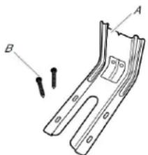
A. Anti-tip bracket
B. #12 x 8" (41 mm) screws (2)
Anti-tip bracket must be securely mounted to floor or wall. Thickness of flooring may require longer screws to anchor bracket to floor.
Parts needed
If using a power supply cord kit:
A UL listed power supply cord kit marked for use with rang The cord should be rated at 250 V minimum, 40 A or 50 is marked for use with normal(315 cm) diameter connection opening and must end in ring terminals or open-end spade terminals with upturned ends.
A UL listed strain relief.
Check local codes. Check existing electrical supply. See the appropriate "Electrical Requirements" section.
It is recommended that all electrical connections be made by a licensed, qualified electrical installer.
NOTE: Be sure to purchase only Whirlpool factory-certified parts and accessories for your appliance. Your installation may require additional parts. To order, refer to the contact information referenced in your Quick Start Guide.
Location Requirements
IMPORTANT: Observe all governing codes and ordinances.
- To eliminate the risk of burns or fire by reaching over heated surface units, cabinet storage space located above the surface units should be avoided. If cabinet storage is to be provided, the risk can be reduced by installing a range hood that provides horizontally a minimum of 5 inches beyond the bottom of the cabinets.
It is the installer's responsibility to comply with installation clearances specified on the model/serial/rating plate. The model/serial/rating plate is located on the frame behind a top rated corner of the door or either side of the drawer.
The range should be located for convenient use in the kitchen - Recessed installations must provide complete enclosure of the sides and rear of the range.
All openings in the wall or floor where range is to be insta must be sealed.
Cabinet opening dimensions that are shown must be used. Given dimensions are minimum clearances.
The anti-tip bracket must be installed. To install the anti-tip bracket shipped with the range, see the "Install Anti-Tip Bracket" section.
Grounded electrical supply is required. See the appropriate "Electrical Requirements" section. - Contact a qualified floor covering installer to check that the floor covering can withstand at least 200^ (93^) .
Use an insulated pad or 1/4'' (0.64 cm) plywood under range installing range over carpeting.
IMPORTANT: To avoid damage to your cabinets, check with your builder or cabinet supplier to make sure that the materials used will not discolor, delaminate or sustain other damage. This oven has been designed in accordance with the requirements of UL and CSA International and complies with the maximum allowable wood cabinet temperatures of 194^ (90^) .
Mobile Home - Additional Installation Requirements
The installation of this range must conform to the ManufactureNet is covered by not less than 1/4'' (0.64 cm) flame retard Home Construction and Safety Standard, Title 24 CFR, Part 28834 covered with not less than No. 28 MSG sheet steel, (formerly the Federal Standard for Mobile Home Construction 0.015" (0.4 mm) stainless steel, 0.024" (0.6 mm) aluminum or Safety, Title 24, HUD Part 280). When such standard is not 0.020" (0.5 mm) copper.
applicable, use the Standard for Manufactured
ANSI A225.1/NFPA 501A or with local codes.
In Canada, the installation of this range must conform with current standards CAN/CSA-Z240.1-latest edition, or with local codes.
Mobile home installations require:
- When this range is installed in a mobile home, it must be secured according to the instructions in this document.
Four-wire power supply cord or cable must be used in home installation. The appliance wiring will need to be See "Electrical Connection - U.S.A. Only" section.
Cabinet Dimensions
Cabinet opening dimensions shown are for 25" (64.0 cm) countertop depth, 24" (61.0 cm) base cabinet depth and 36" (91.4 cm) countertop height.
IMPORTANT: If installing a range hood or microwave hood combination above the range, follow the range hood or microwave hood combination installation instructions for dimensional clearances above the cooktop surface.
A freestanding range may be installed next to combustible with zero clearance.
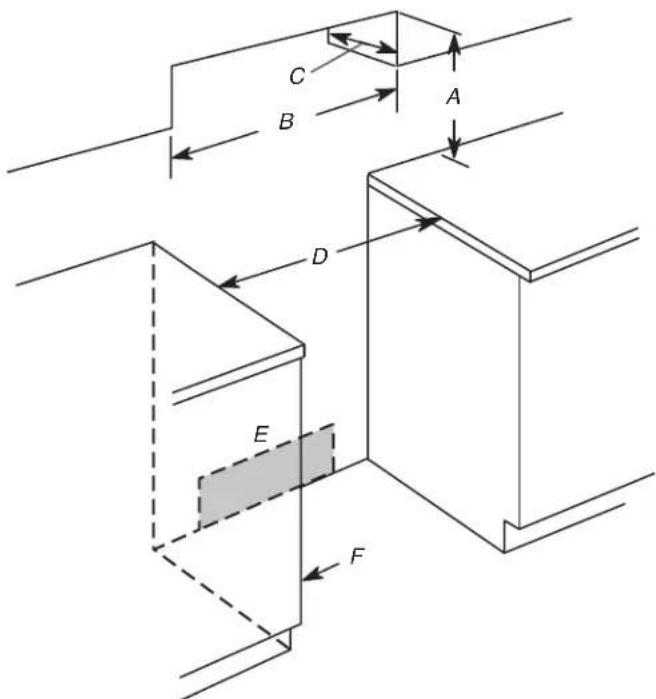
A. For minimum clearance to top of cooktop, see NOTE*
B. 30^ (76.2 cm) minimum opening width
C. 13'' (33.0 cm) maximum upper cabinet depth
D. 30^ (76.2 cm) minimum opening width
E. Outlet - 8" (20.3 cm) to 22" (55.9 cm) from either cabinet, 7" (17.8 cm) maximum from floor.
F. Cabinet door or hinges should not extend into the cutout.
*NOTE: 24" (61.0 cm) minimum when bottom of wood or metal ca nnet is covered by not less than 1 / 4" (0.64 cm) flame retard mddard covered with not less than No. 28 MSG sheet steel, 0.015" (0.4 mm) stainless steel, 0.024" (0.6 mm) aluminum or 0.020" (0.5 mm) copper.
50^ (76.2 cm) minimum clearance between the top of the cook platform and the bottom of an uncovered wood or metal cabinet
Electrical Requirements - U.S.A. Only
If codes permit and a separate ground wire is used, it is recommended that a qualified electrical installer determine that the ground path and wire gauge are in accordance with local codes.
Do not use an extension cord.
Be sure that the electrical connection and wire size are adequate and in conformance with the National Electrical Code,
ANSI/NFPA 70-latest edition and all local codes and ordinances.
A copy of the above code standards can be obtained from:
National Fire Protection Association
1 BatteryMarch Park
Quincy, MA 02169-7471
WARNING: Improper connection of the equipment-grounding conductor can result in a risk of electric shock. Check with a qualified electrician or service technician if you are in doubt as whether the appliance is properly grounded. Do not modify the power supply cord plug. If it will not fit the outlet, have a preoutlet installed by a qualified electrician.
Electrical Connection
To properly install your range, you must determine the type of range is manufactured with the ground connected to the electrical connection you will be using and follow the instructions by a link. The ground must be revised so the green g provided for it here. wire of the 4-wire power supply cord is connected to the capi
- Range must be connected to the proper electrical voltage. See the "Electrical Connection - U.S.A. Only" section.
frequency as specified on the model/serial/rating plate. The grounding through the neutral conductor is prohibited for new model/serial/rating plate is located on the frame behind a branch-circuit installations (1996 NEC); mobile homes; and corner of the door or either side of the drawer.
A. The model/serial/rating plate is located on the frame behind a top corner of the door or either side of the drawer.
This range is manufactured with the neutral terminal connected to the cabinet. Use a 3-wire, UL listed, 40 or 4050A circuit power supply cord (pigtail). See the following Range Rating No.-8 conductors chart. If local codes do not permit ground through the neutral-10 white neutral use a 4-wire power supply cord rated at 250 V, 40 or 150No-8aquaen grounding investigated for use with ranges. If connecting to a 3-wire
Range Rating* Specified Rating of
Power Supply Cord Kit and Circuit Protection
120/240 V 120/208 V Ampere
| 8.8-16.5 kW | 7.8-12.5 kW | 40 or 50** |
| 16.6-22.5 kW | 12.6-18.5 kW | 50 |
*The NEC calculated load is less than the total connected load listed on the model/serial/rating plate.
**If connecting to a 50 A circuit, use a 50 A rated cord with kit. For 50 A rated cord kits, use kits that specify use with 18 a nominal 1 (34.9 mm) diameter connection opening.
A circuit breaker is recommended.
The range can be connected directly to the circuit breaker box (or fused disconnect) through flexible or nonmetallic sheathed, copper or aluminum cable. See the "Electrical Connection - U.S.A. Only" section.
- Allow 2 to 3 ft (61.0 cm to 91.4 cm) of slack in the line so that the range can be moved if servicing is ever necessary.
A UL listed conduit connector must be provided at each end of the power supply cable (at the range and at the junction box).
Wire sizes and connections must conform with the rating of the range.
The Tech Sheet is located on the back of the range inside a clear plastic bag.
If connecting to a 4-wire system:
This range is manufactured with the ground connected to the terminal by a link. The ground must be revised so the green gap wire of the 4-wire power supply cord is connected to the cabin
Seed the "Electrical Connection - U.S.A. Only" section.
Grounding through the neutral conductor is prohibited for new branch-circuit installations (1996 NEC); mobile homes; and recreational vehicles, or an area where local codes prohibit grounding through the neutral conductor.
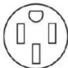
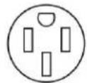
When a 4-wire receptacle of NEMA Type 14-50R is used, a matching UL listed, 4-wire, 250 V, 40 or 50 A, range power s cord (pigtail) must be used. This cord contains 4 copper conductors with ring terminals or open-end spade terminals with upturned ends, terminating in a NEMA Type 14-50P plug on supply end.
The fourth (grounding) conductor must be identified by a green green/yellow cover and the neutral conductor by a white cover. Cord should be Type SRD or SRDT with a UL listed strain re and be at least 4 ft (1.22 m) long.
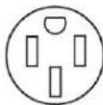
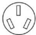
4-wire receptacle (14-50R)
The minimum conductor sized for the copper 4-wire power cord are:
4050A circuit
Fig No.-8 conductors
Neutral, -10 white neutral
15NoA-8a geleen grounding
If connecting to a 3-wire system:
Local codes may permit the use of a UL listed, 3-wire, 250 V 50 A range power supply cord (pigtail). This cord contains 3 copper conductors with ring terminals or open-end spade terminals with upturned ends, terminating in a NEMA Type 10-5 plug on the supply end. Connectors on the appliance end must provided at the point the power supply cord enters the appliance. This uses a 3-wire receptacle of NEMA Type 10-50R.
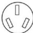
3-wire receptacle (10-50R)
Electrical Requirements - Canada Only
AWARNING

Electrical Shock Hazard
Electrically ground appliance.
Failure to do so could result in death, fire, or elect shock.
If codes permit and a separate ground wire is used, it is recommended that a qualified electrical installer determine that the ground path is adequate and wire gauge are in accordance with local codes.
Be sure that the electrical connection and wire size are adequate and in conformance with CSA Standard C22.1, Canadian Electrical Code, Part 1 - latest edition, and all local codes and ordinances.
A copy of the above code standards can be obtained from:
Canadian Standards Association
178 Rexdale Blvd.
Toronto. ON M9W 1R3 CANADA
- Check with a qualified electrical installer if you are not range is properly grounded.
Range Rating* Specified Rating of Power Supply Cord Kit and Circuit Protection
| 120/240 V | 120/208 V | Amps | ||
| 8.8-16.5 kW | 7.8-12.5 kW | 40 or 50** | ||
| 16.6-22.5 kW | 12.6-18.5 kW | 50 | ||
*The NEC calculated load is less than the total connected load listed on the model/serial/rating plate.
**If connecting to a 50 A circuit, use a 50 A rated cord with kit. For 50 A rated cord kits, use kits that specify use with a nominal 1/8'' (34.9 mm) diameter connection opening.
A time-delay fuse or circuit breaker is recommended.
This range is equipped with a CSA International Certified Power Cord intended to be plugged into a standard 14-50R wall receptacle. Be sure the wall receptacle is within reach of range's final location.
Do not use an extension cord.
INSTALLATION
Unpack Range
AWARNING
Excessive Weight Hazard
Use two or more people to move and install or uninstall appliance.
Failure to do so can result in back or other injury.
-
Remove shipping materials, tape and film from range.
-
Remove oven racks and parts package from inside oven.
-
Do not remove the shipping base at this time.
A. Shipping base
4. On Ranges Equipped with a Storage Driver:
Remove the storage drawer. See the "StorageDrawer" section. Use a 1/4" (6.4 mm) drive ratchet to lower the real leveling legs one-half turn. Use a wrench or pliers to lower front leveling legs one half turn.
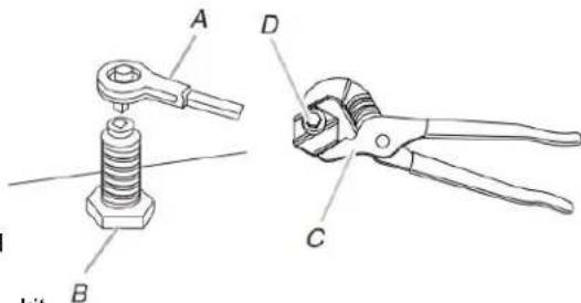
A. 1 / 4'' (6.4 mm) drive ratchet
C. Wrench or pliers D. Front leveling leg
B. Rear leveling leg
On Ranges Equipped with a Warming Printer or PremiOn Storage Printer:
On ranges equipped with a warming drawer or premium storage drawer, the rear legs cannot be accessed by removing the warming drawer or premium storage drawer. It will be from necessary to adjust the rear legs from outside the range. Use wrench or pliers to lower the front and rear leveling legs one half turn.
Determine and mark centerline of the cutout space. The mounting can be installed on either the left-side or right-side the cutout. Position mounting bracket against the wall in the cutout so that the V-notch of the bracket (S1.B2 cm) from centerline as shown.
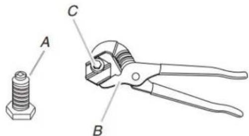
A. Rear leveling leg
B. Wrench or pliers
C. Front leveling leg
Install Anti-Tip Bracket
AWARNING

Tip Over Hazard
A child or adult can tip the range and be killed.
Install anti-tip bracket to floor or wall per installation instructions.
Slide range back so rear range foot is engaged in the slot of the anti-tip bracket.
Re-engage anti-tip bracket if range is moved.
Do not operate range without anti-tip bracket installed and engaged.
Failure to follow these instructions can result in death serious burns to children and adults.
- Remove the anti-tip bracket from where it is taped inside storage drawer or warming drawer.
- Determine which mounting method to use: floor or wall. If you have a stone or masonry floor, you can use the mounting method. If you are installing the range in a me home, you must secure the range to the floor.
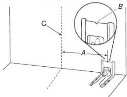
A. 129 / 16'' (31.9 cm)
B. Bracket V-notch
C. Centerline
- Drill two 1/8 (3 mm) holes that correspond to the bracket holes of the determined mounting method. See the following illustrations.
Floor Mounting
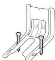
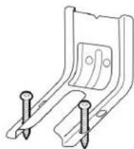
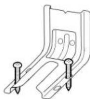
Rear Position Front Position Diagonal (2 options)
Wall Mounting
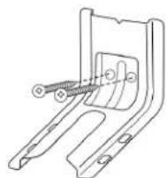
- Using the Phillips screwdriver, mount anti-tip bracket to the wall or floor with the two 2 (41.3 mm) screws provided.
- Move range close enough to opening to allow for final electrical connections. Remove shipping base, cardboard or the hardboard from under range.
- Move range into its final location, making sure rear leveling slides into anti-tip bracket.

- Move range forward onto shipping base, cardboard or hardboard to continue installing the range using the following installation instructions.
Adjust Leveling Legs
- If range height adjustment is necessary, use a wrench to loosen the four leveling legs.
This may be done with the range on its back or with supported on two legs after the range has been placed a standing position.
NOTE: To place range back up into a standing position sheet of cardboard or hardboard in front of range. Using or more people, stand range back up onto the cardboard hardboard.
Level Range
Dependent if you have AquaLeithnology or Steam Clean by referring to the "Range Maintenance and Care" section.
For Ranges with AqualffTechnology or Steam Back: Clean:
- Place level on the oven bottom as indicated in one of the figures below depending on the size of the level. Check with the level: side to side and front to back.
AWARNING

Tip Over Hazard
A child or adult can tip the range and be killed.
Install anti-tip bracket to floor or wall per installation instructions.
Slide range back so rear range foot is engaged in the slot of the anti-tip bracket.
Re-engage anti-tip bracket if range is moved.
Do not operate range without anti-tip bracket installed and engaged.
Failure to follow these instructions can result in death or serious burns to children and adults.
- If range is not level, pull range forward until rear leveling is removed from the anti-tip bracket.
- Follow the directions in Style 1 or Style 2, depending on the style of drawer supplied with the range.
For Ranges without AqualiFFtechnology or
Steam Clean:
- Place a standard flat rack in oven.
- Place level on the rack and check levelness of the range, side to side; then front to back.
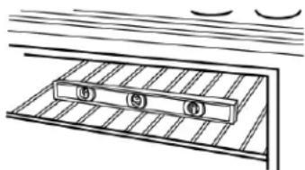
Fig. 2. Measure the distance from the top of the counter to the 3^ flange range is not level, pull range forward until rear leveling is reached.
3. Measure the distance from the top of the cooktop to the 4. Follow the directions in Style 1 or Style 2, depending on the bottom of the leveling legs. This distance should be the same style of drawer supplied with the range.
If it is not, adjust the leveling legs to the correct height leveling leg can be lowered to add up to a maximum
Style 1: Ranges Equipped with a Storage Driver:
1" (2.5 cm). A minimum of 3/16" (5 mm) is needed to engage 1/4 (0.64 cm) drive ratchet, wrench or pliers to adjust the anti-tip bracket.
NOTE: If height adjustment is made when range is standing, position. Check that rear leveling leg is engaged in the area to tilt the range back to adjust the front legs, and then tilfevertard
to adjust the rear legs.
Style 2: Ranges Equipped with a Warming Printer or Premium Storage Printer:
When the range is at the correct height, check that the Premium Storage Driver:
adequate clearance under the range for the anti-tip bracket. Use a wrench or pliers to adjust leveling legs up or down un
Before sliding range into its final location, check that the range is level. Push range back into position. Check that rear
anti-tip bracket will slide under the range and onto the real leveling leg prior to anti-tip bracket installation. leveling leg is engaged in the anti-tip bracket.
NOTE: Range must be level for satisfactory baking performance.
be higher than the counter. See the Installation Instructions.
Clean functions.
Electrical Connection - U.S.A. Only
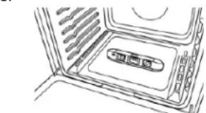
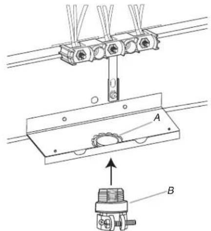
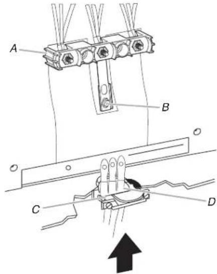
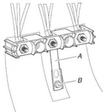
- Remove the three 10-32 hex nuts from the terminal posts.
Power Supply Cord
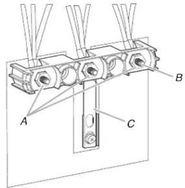
A. 10-32 hex nuts
B. Terminal Posts
C. Ground-link strap
-
Add strain relief.
-
Disconnect power.
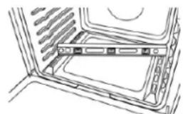
- Remove the terminal block cover screws located on the back Remove the knockout for the power supply cord. of the range.Pull cover down and toward you to remove oAssemble a UL listed strain relief in the opening. from range.
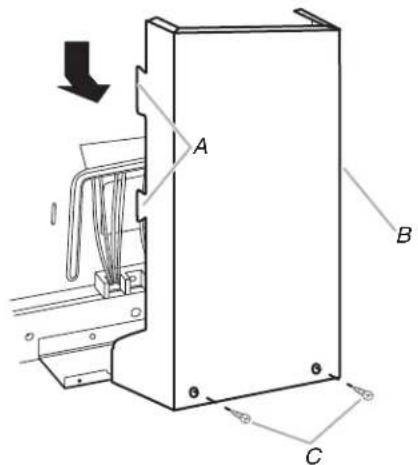
A. Two mounting tabs each side
B. Terminal block cover
C. Hex-head screws
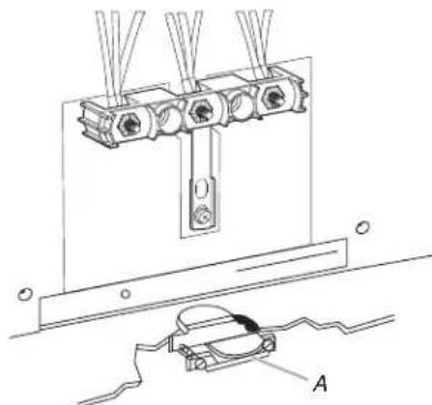
A. UL listed strain relief
Tighten strain relief screw against the power supply cord.
Style 2: Direct wire strain relief
Remove the knockout as needed for the flexible conduit connection. If
■ Assemble a UL listed conduit connector in the opening.
A. Removable retaining nut
B. Conduit
Tighten strain relief screw against the flexible conduit.
- Complete installation following instructions for your type of electrical connection:
4-wire (recommended)
3-wire (if 4-wire is not available)
Electrical Connection Options
| If your home has: | And you will be connecting to: | Go to Section: |
4-wire receptacle A UL Listed, 250 4wire connection: (NEMA type 14-50R) minimum, 40 A, Power supply cord range power supply cord
4-wire direct
A. 3 / 8^n(1cm)
B. 5^ (12cm)
3-wire receptacle A UL Listed, 250 3wire connection: (NEMA type 10-50R)minimum, 40 A, Power supply cord range power supply cord
3-wire direct
A. 3 / 8'' (1 cm)
B. 3^ (7.6 ~cm)
A circuit breaker 3-wire connection: box or fused Direct wire disconnect
4-Wire Connection: Power Supply Cord
Use this method for:
New branch-circuit installations (1996 NEC)
Mobile homes
Recreational vehicles
In an area where local codes prohibit grounding through the neutral
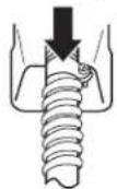
- Part of Ground-link strap must be cut out and removed.
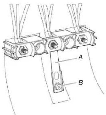
A. Ground-link strap
B. Ground-link screw
-
Use a Phillips screwdriver to remove the ground-link screw-Wire Connection: Power Supply Cord from the back of the range. Save the ground-link screw used this method only if local codes permit connecting chassis the end of the ground link under the screw. ground conductor to neutral wire of power supply cord.
-
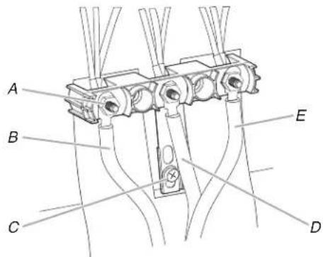
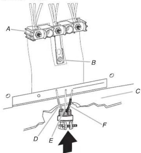
Feed the power supply cord through the strain relief on the feed the power supply cord through the strain relief in the cord/conduit plate on bottom of range. Allow enough slack to load the conduit plate on bottom of range. Allow enough slack to easily attach the wiring to the terminal block.
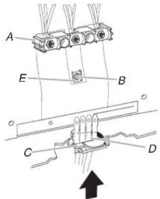
A. Terminal block
C. UL listed strain relief
B. Ground-link
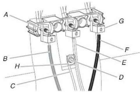
D. Power supply cord wires
E. Ground-link strap end piece
-
Use Phillips screwdriver to connect the green ground wire from the power supply cord to the range with the ground-link screw. Insert the ground-link screw through the ground-link strap end piece and the green ground wire. The ground wire must be attached first.
-
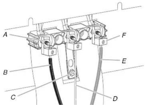
Use 3/8" (9.5 mm) nut driver to connect the neutral (white) wire to the center terminal block post with one of the 20-hex nuts.
A. 10-32 hex nut
D. Green ground wire
B. Ground-link
E. Neutral (center) wire
screw
F. Line 1 (black)
C. Line 2 (red)
G. Ground-Link strap end piece
-
Connect line 2 (red) and line 1 (black) wires to the outer terminal block posts with 10-32 hex nuts.
-
Using a torque wrench, tighten the hex nuts to a recommended torque of 20 in-lbs (2.3 N-m).
NOTE: For power supply cord replacement, use only a cord rated at 250 V minimum, 40 A or 50 A that is use with nominal/1"1 (3.5 cm) diameter connection opening with ring terminals and marked for use with ranges.
- Tighten strain relief screws.
IMPORTANT: Verify the tightness of the hex nuts.
-
Replace terminal block access cover.
-
Reconnect power.
A. Terminal block
C. UL listed strain relief
B. Ground-link
D. Power supply cord
wires - large opening
ge 3/8" (9.5 mm) nut driver to connect the neutral (white) wire to the center terminal block post with one of the 10-3 hex nuts.
A. 10-32 hex nut
D. Neutral (white) wire
B. Line 2 (red)
E. Line 1 (black)
C. Ground-link
screw
-
Connect line 2 (red) and line 1 (black) wires to the outer terminal block posts with 10-32 hex nuts.
-
Using a torque wrench, tighten the hex nuts to a recommended torque of 20 in-lbs (2.3 N-m).
power
marked for power supply cord replacement, only use a power
cord rated at 250 V minimum, 40 A or 50 A that is mark
use with nominal/8"1 (3.5 cm) diameter connection opening,
with ring terminals and marked for use with ranges.
- Tighten strain relief screws.
IMPORTANT: Verify the tightness of the hex nuts. - Replace terminal block access cover.
- Reconnect power.
Direct Wire
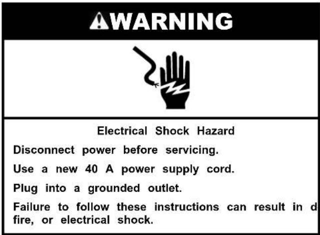
AWARNING

Electrical Shock Hazard
Disconnect power before servicing.
Use 8 gauge copper or 6 gauge aluminum wire.
Electrically ground range.
Failure to follow these instructions can result in death, fire, or electrical shock.
Direct Wire Installation: Copper or Aluminum Wire
This range may be connected directly to the fuse disconnect circuit breaker box. Depending on your electrical supply, make required 3-wire or 4-wire connection.
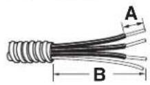
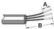
- Strip outer covering back 3" (7.6 cm) to expose wires. Stripblock. the insulation back 1" (2.5 cm) from the end of each wire.
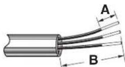
A. 3 / 8'' (1 cm)
B. 3'' (7.6 cm)
- Allow enough slack in the wire to easily attach the wiring terminal block.
- Complete electrical connection according to your type of electrical supply.
4-wire (recommended)
3-wire (if 4-wire is not available)
4-Wire Connection: Direct Wire
Use this method for:
New branch-circuit installations (1996 NEC)
Mobile homes
Recreational vehicles
In an area where local codes prohibit grounding through the neutral
- Part of Ground-link strap must be cut out and removed.
A. Ground-link strap
B. Ground-link screw
Use a Phillips screwdriver to remove the ground-link screw from the back of the range. Save the ground-link screw and the end of the ground link under the screw.
Pull the wires through the strain relief on bottom of range. Allow enough slack to easily attach wiring to the terminal
A. Terminal block
B. Ground-link screw
C. Cord/conduit plate
D. Bare (green) ground wire
E. Line 2 (red) wire
F. Neutral (white) wire
G. Line 1 (black) wire
H. Ground-Link strap end piece
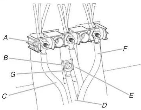
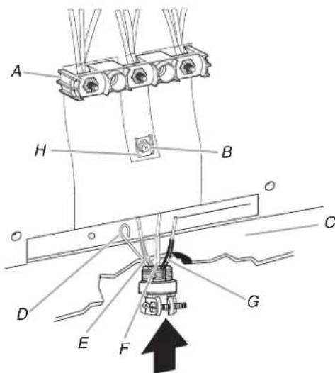
- Attach terminal lugs to line 1 (black), neutral (white), and 3-Wire2 Connection: Direct Wire
(red) wires. Loosen (do not remove) the setscrew on the roth this method only if local codes permit connecting ground of the terminal lug and insert exposed wire end throughconductor to neutral supply wire.
bottom of terminal lugs. Securely tighten setscrew to torque the wires through the conduit on cord/conduit plate on shown in the following Bare Wire Torque Specifications chart bottom of range. Allow enough slack to easily attach the w
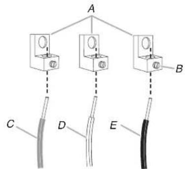
A. Terminal lug
D. Neutral (white) wire
B. Setscrew
E. Line 1 (black) wire
C. Line 2 (red) wire
Bare Wire Torque Specifications
Wire Awg Torque
8 gauge copper 25 lbs-in (2.8 N-m)
6 gauge aluminum 35 lbs-in (4.0 N-m)
-
Use a hex or Phillips screwdriver to connect the bare (green) ground wire to the range with the ground-link screw and ground-link section. Insert the ground-link screw through the ground-link strap end piece and the green ground wire. The ground wire must be attached first.
-
Use 3/8" (9.5 mm) nut driver to connect the neutral (white) the front of the terminal lug and insert exposed wire end wire to the center terminal block post with one of the 10-32 through bottom of terminal lugs. Securely tighten setscrew to hex nuts. torque as shown in the following Bare Wire Torque Specifications chart.
A. 10-32 hex nut
E. Neutral (white) wire
B. Line 2 (red)
F. Line 1 (black)
C. Bare (green) ground wire
G. Terminal lug H. O. V. H.
D. Ground-link screw
H. Ground-Link strap end piece
-
Connect line 2 (red) and line 1 (black) wires to the outer terminal block posts with 10-32 hex nuts.
-
Using a torque wrench, tighten the hex nuts to a recommended torque of 20 in-lbs (2.3 N-m).
-
Securely tighten hex nuts.
IMPORTANT: Verify the tightness of the hex nuts. -
Replace terminal block access cover.
-
Reconnect power.
A. Terminal block
D. Line 2 (red) wire
B. Ground-link
E. Bare (green) ground wire
screw
F. Line 1 (black) wire
C. Cord/conduit
plate
- Attach terminal lugs to line 2 (red), bare (green) ground, and line 1 (black) wires. Loosen (do not remove) the setscrew o
the front of the terminal lug and insert exposed wire end through bottom of terminal lugs. Securely tighten setscrew to torque as shown in the following Bare Wire Torque Specifications chart.

A. Terminal lug
D. Bare (green) ground wire
B. Setscrew
E. Line 1 (black) wire
C. Line 2 (red) wire
Bare Wire Torque Specifications
| Wire Awg Torque |
| 8 gauge copper 25 lbs-in (2.8 N-m) |
| 6 gauge aluminum 35 lbs-in (4.0 N-m) |
- Use 3/8" (9.5 mm) nut driver to connect the bare (green) Ranges Equipped with a Warming Printer or Premium ground wire to the center terminal block post with one Storage Printer:
A. 10-32 hex nut
D. Bare (green) ground wire
B. Line 2 (red)
E. Line 1 (black)
C. Ground-link
F. Terminal lug
screw
- Connect line 2 (red) and line 1 (black) wires to the outer terminal block posts with 10-32 hex nuts.
- Using a torque wrench, tighten the hex nuts to a recommended torque of 20 in-lbs (2.3 N-m).
- Securely tighten hex nuts.
IMPORTANT: Verify the tightness of the hex nuts.
- Replace terminal block access cover.
- Reconnect power.
Verify Anti-Tip Bracket Is Installed and Engaged
On Ranges Equipped with a Storage Printer:
- Remove the storage drawer. See "Storage Drawer" section.
- Use a flashlight to look underneath the bottom of the ran
-
Visually check that the rear range foot is inserted into the of the anti-tip bracket.
-
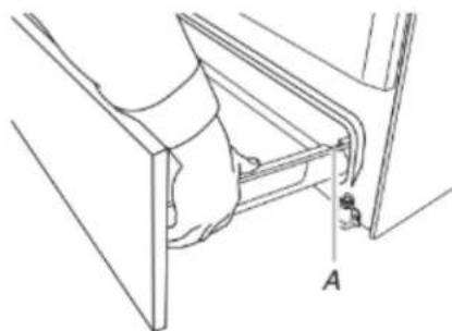
Place the outside of your foot against the bottom front of the warming drawer or premium storage drawer, and grasp the lower right or left side of the control panel as shown.
NOTE: If your countertop is mounted with a backsplash, it may be necessary to grasp the range higher than is shown the illustration.
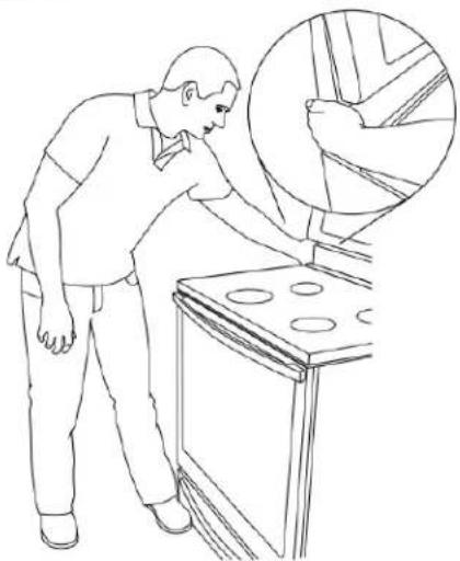
- Slowly attempt to tilt the range forward.
If you encounter immediate resistance, the range foot is engaged in the anti-tip bracket. - If the rear of the range lifts more than 1/2 (1.3 cm) off t without resistance, stop tilting the range and lower it gently back to the floor. The range foot is not engaged in the a bracket.
**tion. ** IMPORTANT: If there is a snapping or popping sound when the range-fifting the range, the range may not be fully engaged in this to the bracket. Check to see if there are obstructions keeping the range from sliding to the wall or keeping the range foot from sliding into the bracket. Verify that the bracket is held securely in place by the mounting screws.
- Slide the range forward, and verify that the anti-tip bracket securely attached to the floor or wall.
- Slide range back so the rear range foot is inserted into the of the anti-tip bracket.
IMPORTANT: If the back of the range is more than 2" (5.) from the mounting wall, the rear range foot may not engage the bracket. Slide the range forward and determine if there is an obstruction between the range and the mounting wall. If you need assistance or service, refer to the Quick Start Gu for contact information.
- Repeat steps 1 and 2 to ensure that the range foot is eng in the anti-tip bracket.
If the rear of the range lifts more than 1/2 (1.3 cm) off without resistance, the anti-tip bracket may not be installed correctly. Do not operate the range without anti-tip bracket installed and engaged. Please refer to the Quick Start Guide for contact information.
Warming Printer or Premium Storage Printer (on some models)
Storage Printer (on some models)
The storage drawer can be removed. Before removing, make sure the drawer is cool and empty.
Remove:
Remove all items from inside the warming drawer or premium storage drawer, and allow the range to cool completely before attempting to remove the drawer. 1.
- Pull the storage drawer straight back to the drawer stop.
To Remove:
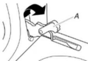
- Open the warming drawer or premium storage drawer to its fully open position.
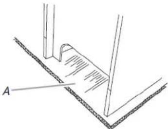
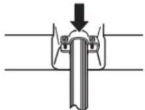
- Using a flat-blade screwdriver, gently loosen the warming drawer or premium storage drawer from the glide alignment notch and lift up the drawer alignment tab from the glide.
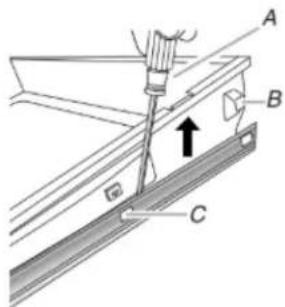
A. Flat-blade screwdriver
B. Drawer alignment tab
C. Drawer glide notch
- Repeat Step 2 on the other side. The warming drawer or premium storage drawer is no longer attached to the drawer glides. Using both hands, pick up the warming drawer or premium storage drawer to complete the removal.
To Replace:
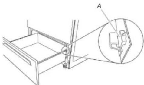
- Align the forward drawer notches with the notches in the drawer glides on both sides. Place the rear alignment tabs into the drawer glides on both sides.
A. Drawn alignment tab
B. Drawer glide notch
- Push the warming drawer or premium storage drawer in all the way.
- Gently open and close the warming drawer or premium storage drawer to ensure it is seated properly on the glides on both sides.
A. Drawer stop notch
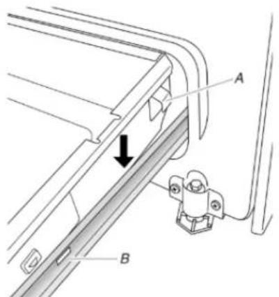
- Lift up the front of the drawer and pull the drawer out.
To Replace:
- Lift up the front of the drawer and place the rear of the inside the range so that the drawer stop notch is behind the drawer glide.
- Lower the drawer so that the edge of the slide rail drops the slot in the drawer glide.
- Slowly push the drawer into the range.
A. Engage drawer glide.
NOTE: When properly installed, the rear slides on the bottom of the drawer will engage the base rails and the drawer with tip when items are placed in the drawer.
Oven Door
For normal range use, it is not suggested to remove the oven door. However, if removal is necessary, make sure the oven is and cool. Then, follow these instructions. The oven door is hea
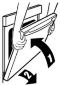
To Remove:
- Open oven door all the way.
- Pinch the hinge latch between two fingers and pull forward. Repeat on other side of oven door.
A. Hinge latch
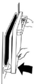
-
Close the oven door as far as it will shut.
-
Lift the oven door while holding both sides.
Continue to push the oven door closed and pull it away from the oven door frame.
To Replace:
- Insert both hanger arms into the door.
- Open the oven door.
You should hear a "click" as the door is set into place.
- Move the hinge levers back to the locked position. Check
the door is free to open and close. If it is not, repeat removal and installation procedures.
Complete Installation
- Check that all parts are now installed. If there is an extra go back through the steps to see which step was skipped.
- Check that you have all of your tools.
- Dispose of/recycle all packaging materials.
- Check that the range is level. See the "Level Range" se
- Use a mild solution of liquid household cleaner and warm water to remove waxy residue caused by shipping mater Dry thoroughly with a soft cloth. For more information, s "Range Maintenance and Care" section.
- Read the Quick Start Guide and online Control Guide.
- Plug power cord into appropriate outlet. Turn power on.
- Turn on surface burners and oven. See the Quick Start and online Control Guide for specific instructions on rang operation.
If Range Does Not Operate, Check the Following:
Household fuse is intact and tight; or circuit breaker not tripped.
- Range is plugged into a grounded outlet.
- Electrical supply is connected.
IMPORTANT: If the range control displays an "F9" or 2:"F9slide range forward.
E0" error code, the electrical outlet in the home may3.bComplete cleaning or maintenance.
miswired. Disconnect power and contact a qualified electrician to verify the electrical supply.
See the online Troubleshooting section.
When the range has been on for 5 minutes, check for heat.
the range is cold, turn off the range and contact a qualified electrician.
Moving the Range
AWARNING

Tip Over Hazard
A child or adult can tip the range and be killed.
Install anti-tip bracket to floor or wall per installation instructions.
Slide range back so rear range foot is engaged in the slot of the anti-tip bracket.
Re-engage anti-tip bracket if range is moved.
Do not operate range without anti-tip bracket installed and engaged.
Failure to follow these instructions can result in death or serious burns to children and adults.
When moving range, slide range onto cardboard or hardboard to avoid damaging the floor covering.
If removing the range is necessary for cleaning or maintenance:
For power supply cord-connected ranges:
at
2. Unplug the power supply cord.
3. Complete cleaning or maintenance.
4. Plug in power supply cord.
5. Check that the anti-tip bracket is installed and engaged. See extra tip/“Verify Anti-Tip Bracket Is Installed and Engaged” section of Check that range is level.
For direct-wired ranges:
AWARNING

Guide
Electrical Shock Hazard
Disconnect power before servicing.
Replace all parts and panels before operating.
Failure to do so can result in death or electrical shock.
- Disconnect power.
2.Fslide range forward.
3.bComplete cleaning or maintenance. - Check that the anti-tip bracket is installed and engaged. See the "Verify Anti-Tip Bracket Is Installed and Engaged" section
- Check that range is level.
6heRecnect power.
SECURITE DE LA CUISINIÈRE
National Fire Protection Association
1 BatteryMarch Park
Quincy, MA 02169-7471
Prise murale (type NEMA
a 4 fBordon 14-50R)d'alimentation
Prise murale (type NEMA
a 3 fiBordon 10-50R)d'alimentation
National Fire Protection Association
1 BatteryMarch Park
Quincy, MA 02169-7471
Toronto, ON M9W 1R3 CANADA
Use this method para:
Aluminio, calibre 6 35 Ib-in (4,0 Nm)
Aluminio, calibre 6 35 Ib-in (4,0 Nm)

- ELECTRIC FREESTANDING RANGE OWNER'S MANUAL
- GUIDE D'UTILISATION DE LA CUISINIÈRE ÉLECTRIQUE AUTOPORTANTE
- MANUAL DEL PROPIETARIO DE LA ESTUFA AUTONOMA ELECTRICA
- Table of Contents/Table des matieres/Indice
- Your safety and the safety of others are very important.
- ADANGER
- WARNING
- IMPORTANT SAFETY INSTRUCTIONS
- SAVE THESE INSTRUCTIONS
- RANGE MAINTENANCE AND CARE
- Self-Cleaning Cycle (on some models)
- AWARNING
- Prepare Range:
- How the Cycle Works
- General Cleaning
- EXTERIOR PORCELAIN ENAMEL SURFACES (on some models)
- Cleaning Method:
- STAINLESS STEEL (on some models)
- METALLIC PAINT (on some models)
- CERAMIC GLASS COOKTOP CLEANING Cleaning Method:
- COOKTOP CONTROLS
- CONTROL PANEL AND OVEN DOOR EXTERIOR
- COIL ELEMENTS (on some models)
- Do not clean or immerse in water. Soil will burn off when hot BURNER BOWLS (on some models)
- Chrome burner bowls
- SURFACE UNDER COOKTOP (on some models)
- OVEN RACKS
- STORAGE DRAWER OR WARMING DRAWER (on some models)
- OVEN CAVITY
- INSTALLATION INSTRUCTIONS REQUIREMENTS
- Tools and Parts
- Tools needed
- Parts supplied
- Parts needed
- Location Requirements
- Mobile Home - Additional Installation Requirements
- Mobile home installations require:
- Cabinet Dimensions
- Electrical Requirements - U.S.A. Only
- Electrical Connection
- Range Rating* Specified Rating of
- Power Supply Cord Kit and Circuit Protection
- If connecting to a 4-wire system:
- If connecting to a 3-wire system:
- Electrical Requirements - Canada Only
- Electrical Shock Hazard
- INSTALLATION
- Unpack Range
- On Ranges Equipped with a Storage Driver:
- Install Anti-Tip Bracket
- Tip Over Hazard
- Floor Mounting
- Wall Mounting
- Adjust Leveling Legs
- Level Range
- For Ranges with AqualffTechnology or Steam Back: Clean:
- For Ranges without AqualiFFtechnology or
- Steam Clean:
- Electrical Connection - U.S.A. Only
- Power Supply Cord
- Style 2: Direct wire strain relief
- Electrical Connection Options
- 4-Wire Connection: Power Supply Cord
- Direct Wire
- Direct Wire Installation: Copper or Aluminum Wire
- 4-Wire Connection: Direct Wire
- Bare Wire Torque Specifications
- Verify Anti-Tip Bracket Is Installed and Engaged
- Warming Printer or Premium Storage Printer (on some models)
- Storage Printer (on some models)
- To Remove:
- To Replace:
- Oven Door
- Complete Installation
- Moving the Range
- SECURITE DE LA CUISINIÈRE
Brand : MAYTAG
Model : MER7700LZ
Category : Cooker