
IM5SS - Ice Maker GE - Free user manual and instructions
Find the device manual for free IM5SS GE in PDF.

| Product Type | Automatic Ice Maker (Replacement Kit) |
| Brand | GE |
| Model | IM5SS |
| Ice Production | 7 ice cubes per cycle, approximately 100 to 130 ice cubes per 24 hours |
| Power Supply | 120 V AC (4 or 6 pin adapter depending on model) |
| Required Water Pressure | 40 to 120 psi (2.8 to 8.2 bar) |
| Water Connection | Cold water line (copper or GE SmartConnect tubing) |
| Operating Temperature | Freezer compartment at -9°C (15°F) or below |
| Functions | Automatic shut-off when bin is full, green indicator light, on/off switch |
| Safety | Do not put fingers in the machine; unplug the refrigerator before installation |
| Maintenance | Clean the ice bin regularly; discard the first batches of ice cubes |
| Parts Included | Ice maker, bin, water valve, tubing, adapters, clamps, bracket, warranty label |
| Warranty | 1 year parts and labor |
| Installation | Basic skill level; duration 20 to 60 minutes |
| Normal Noise | Humming of the water valve and sound of ice cubes dropping |
| Compatibility | GE side-by-side refrigerators requiring kits IM-1, IM-2, or IM-3 |
| Troubleshooting | If the green light flashes, ice cubes are jammed; set switch to 0 and remove the ice cubes |
| Power Consumption | Not specified |
| Weight | Not specified |
| Dimensions | Varies depending on the refrigerator |
Frequently Asked Questions - IM5SS GE
User questions about IM5SS GE
0 question about this device. Answer the ones you know or ask your own.
Ask a new question about this device
Download the instructions for your Ice Maker in PDF format for free! Find your manual IM5SS - GE and take your electronic device back in hand. On this page are published all the documents necessary for the use of your device. IM5SS by GE.
USER MANUAL IM5SS GE
Icemaker Accessory Kit
Safety Information 2
Operating Instructions 3
Before You Call For Service . . .4
Normal Sounds
You May Hear 3
Preparing for Vacation .3
When You Should
Set the Icemaker
Power Switch to 0 (Off) .3
Installation Instructions
Cold Water Line. 16-19
Icemaker C. 8-11
Icemaker K. 12-15
Parts List 6,7
Consumer Support
Consumer Support...Back Cover
Warranty 20
Which instructions should you follow?
Look for a label on the back of the refrigerator that will tell you which instructions to use:
C or K
Owner's Manual and Installation Instructions
Kit IM-5SS
This kit fits most side-by-side models calling for Kit IM-1, IM-2 or IM-3. If you are replacing an icemaker with Kit IM-1 or IM-2, see page 5.
Trousse
Machine à glaçons
197D4257P002 49-60284 06-03 JR


SAFETY PRECAUTIONS
FOR YOUR SAFETY:
Do not place fingers or hands in the automatic icemaking mechanism while the refrigerator is plugged in. This will help protect you from possible injury.
It will also prevent interference with moving parts of the ejector mechanism and the heating element that releases the cubes, located on the bottom of the icemaker.

READ AND FOLLOW THIS SAFETY INFORMATION CAREFULLY. READ AND SAVE THESE INSTRUCTIONS
A newly-installed refrigerator may take 12 to 24 hours to begin making ice.
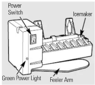
Automatic Icemaker
The icemaker will produce seven cubes per cycle—approximately 100-130 cubes in a 24-hour period, depending on freezer compartment temperature, room temperature, number of door openings and other use conditions.
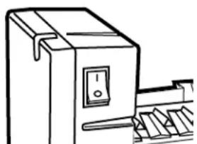
If the refrigerator is operated before the water connection is made to the icemaker, set the power switch to 0 (off).
When the refrigerator has been connected to the water supply, set the power switch to 1 (on). The green light will come on.
The icemaker will fill with water when it cools to freezing. A newly-installed refrigerator may take 12 to 24 hours to begin making ice cubes.
Throw away the first few batches of ice to allow the water line to clear.
Be sure nothing interferes with the sweep of the feeler arm.
When the bin fills to the level of the feeler arm, the icemaker will stop producing ice. It is normal for several cubes to be joined together.
If ice is not used frequently, old ice cubes will become cloudy, taste stale and shrink.
If ice cubes get stuck in the icemaker, the green power light will blink. To correct this, set the power switch to 0 (off) and remove the cubes. Set the power switch to 1 (on) to restart the icemaker.
NOTE: In homes with lower-than-average water pressure, you may hear the icemaker cycle multiple times when making one batch of ice.
Preparing for Vacation
Set the icemaker power switch to 0 (off) and shut off the water supply to the refrigerator.
If the temperature can drop below freezing, have a qualified servicer drain the water supply system (on some models) to prevent serious property damage due to flooding.
When you should set the icemaker power switch to O (off)
When the ice storage bin is removed for more than a minute or two.
When the refrigerator will not be used for several days.
When the water supply will be shut off for several hours.
Normal sounds you may hear
The icemaker water valve will buzz when the icemaker fills with water. If the power switch is in the I (on) position, it will buzz even if it has not yet been hooked up to water. Keeping the power switch in the I (on) position before it is hooked up to water can damage the icemaker. To prevent this, move the power switch to the O (off) position. This will stop the buzzing.
The sound of cubes dropping into the bin and water running in the pipes as the icemaker refills.
Before you call for service...

Troubleshooting Tips
Save time and money! Review the charts on the following
pages first and you may not need to call for service.
| Problem Possible Causes What To Do | ||
| Automatic icemaker does not work the O (off) position. | Icemaker power switch in position. | • Move the switch to the I (on) position. |
| Water supply turned off or not connected. | • See Installing the Water Line. | |
| Freezer compartment too warm cool down. | • Wait 24 hours for the refrigerator to completely | |
| Piled up cubes in the storage • Level cubes by hand. bin cause the icemaker to shut off. | ||
| Cubes too small | Water shutoff valve connecting refrigerator to water line may be clogged. | • Call the plumber to clear the valve. |
| Slow ice cube freezing | Door left open. | • Check to see if package is holding door open. |
| Temperature control not set cold enough. | • See About the Temperature Control. | |
| Ice cubes have odor/taste | Ice storage bin needs cleaning. | • Empty and wash bin. Discard old cubes. |
| Food transmitting odor/taste to ice cubes. | • Wrap foods well. | |
| Interior of refrigerator needs cleaning. | • See Care and cleaning. | |
Installation IM-5SS Instructions Icemaker Kit
Questions? Call 800-GE-CARES (800-432-2737) or Visit our Website at: www.GEApliances.com In Canada, call 1-800-361-3400 or Visit our Website at: www.geappliances.ca
BEFORE YOU BEGIN
Read these instructions completely and carefully.
- IMPORTANT - Save these instructions for local inspector's use.
- IMPORTANT - Observe all governing codes and ordinances.
Note to Installer - Be sure to leave these instructions with the Consumer. - Note to Consumer - Keep these instructions for future reference.
- Skill level - Installation of this appliance requires basic mechanical and electrical skills.
Completion time - 20-60 minutes - Proper installation is the responsibility of the installer.
- Product failure due to improper installation is not covered under the Warranty.
WHICH INSTRUCTIONS SHOULD YOU FOLLOW?
There is a label on the back of the refrigerator that will tell you whether to use Instructions:
C or K
The actual installation of the icemaker will depend on which model refrigerator you have.
ARE YOU REPLACING AN ICEMAKER WITH THIS KIT?
It's important that you use the water valve and fill tube extension that come with this kit, even though your refrigerator may already have them installed.
The old valve will not allow enough water through to fill the icemaker properly and may cause damage.
The fill tube extension needs to be a different length than the original tube for proper water flow. Cut the tube to the length indicated for your model of refrigerator.
DAMAGE - SHIPMENT/INSTALLATION
- If the unit is damaged in shipment, return the unit to the store in which it was bought for repair or replacement.
- If the unit is damaged by the customer, repair or replacement is the responsibility of the customer.
- If the unit is damaged by the installer (if other than the customer), repair or replacement must be made by arrangement between customer and installer.
CONTENTS OF KIT IM-5SS
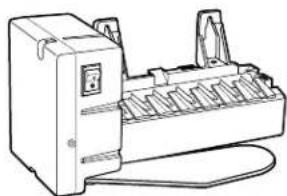
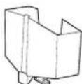
1 Icemaker
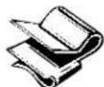
Owner's Manual & Installation Instructions

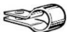
3 Hose Clamp (black)
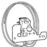
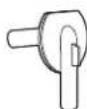
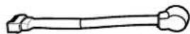
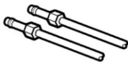
Water Valve and Tube Assembly

Adhesive-Backed Water Line Fasteners

6 Hose Clamp (not black)
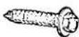
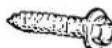
Hex-Head Screw for Water Line Clamp
Water Line Clamp (strain relief)
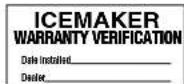
9 Warranty Label
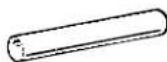
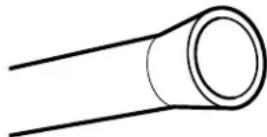
10 Fill Tube Extension (3/4"O.D.)
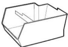
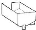
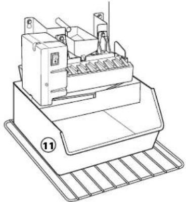
11 Ice Bucket
12 Water Line Clamp (strain relief)

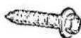
13 Hex-Head Screw
14 Water Tube Inlet

15 Insulated Fill Tube (5/8"O.D.)
Hex-Head Screw (2)
17 Icemaker Fill Cup (side-mounted)
18 Icemaker Fill Cup (center-mounted)

19 Icemaker Insert
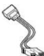
20 Icemaker Power Cord Adapter (4 pin)
21 Icemaker Power Cord Adapter (6 pin)
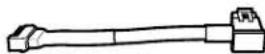
22 Water Valve Wire Adapter

23 Wire Ties (2)
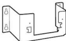
24 Icemaker Bracket
25 Screws to Install Bracket to Refriger. Wall (3)
Parts List Use with Installation Instructions:
| C | K | |
| 1 Icemaker X X | ||
| 2 Owner's Manual and Installation Instructions X | X | |
| 3 Hose Clamp (black) X | ||
| 4 Water Valve and Tube Assembly* X | X | |
| 5 Adhesive-Backed Water Line Fasteners X | X | |
| 6 Hose Clamp (not black) X X | ||
| 7 Hex-Head Screw for Water Line Clamp X | ||
| 8 Water Line Clamp (strain relief) X | ||
| 9 Warranty Label X X | ||
| 10 Fill Tube Extension (3/4" O.D.) | X | |
| 11 Ice Bucket | X | X |
| 12 Water Line Clamp (strain relief) | X | |
| 13 Hex-Head Screw | X | X |
| 14 Water Tube Inlet | X | |
| 15 Insulated Fill Tube (5/8" O.D.) | X | |
| 16 Hex-Head Screw (2) | X | |
| 17 Icemaker Fill Cup (side-mounted) | X | |
| 18 Icemaker Fill Cup (center-mounted) | X | |
| 19 Icemaker Insert | X | |
| 20 Icemaker Power Cord Adapter (4 pin) | X | |
| 21 Icemaker Power Cord Adapter (6 pin) | X | |
| 22 Water Valve Wire Adapter | X | |
| 23 Wire Ties (2) | X | X |
| 24 Icemaker Bracket (on some models) | X | |
| 25 Screws to Install Bracket to Refrigerator Wall (3) | X |
- Always change the water valve when replacing an icemaker that makes round cubes. This new icemaker uses a different voltage which may cause the old valve to fail. For dispenser models, order GE Part Number WR57X96.
ICEMAKER INSTALLATION INSTRUCTIONS C
Are these the right instructions for your model? Follow the Installation Instructions indicated by the label on the back of the refrigerator—
BEFORE YOU BEGIN
Read each step thoroughly before proceeding.
CAUTION - Unplug the Refrigerator. To eliminate the danger of electric shock during installation, you must unplug the refrigerator from its electrical outlet.
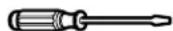
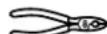
TOOLS YOU WILL NEED
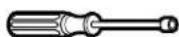
Flat blade and Phillips screwdrivers
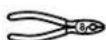
Pliers
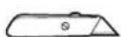
Sharp knife
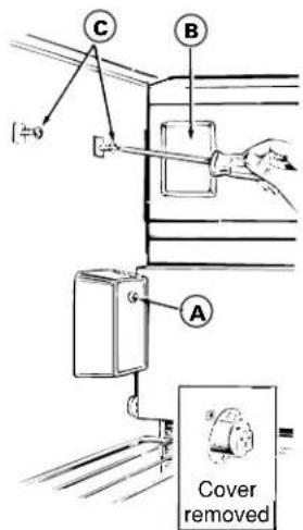
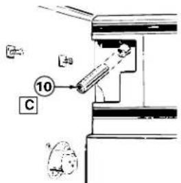
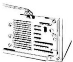
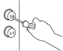
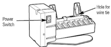
1 PREPARE FOR INSTALLATION
- Remove the screw (A) that holds the electrical plug cover in place. You will not need this screw and cover.
- Remove the light shield insert (B) and discard it.
- Loosen the two mounting screws (C) approximately 1/2'' (13 mm). DO NOT REMOVE THESE SCREWS.
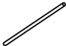
2 INSTALL FILL TUBE EXTENSION
Cut the fill tube extension (10) to the length (refer to the plate in this section) with a sharp knife or single-edge razor blade and slide it onto the fill tube against the stop.
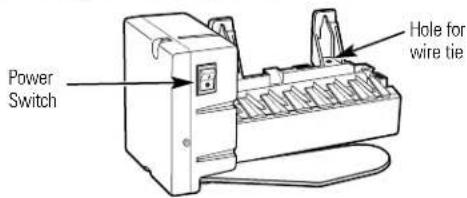
3 SET POWER SWITCH TO O (off)
Set the icemaker power switch to 0 (off). Leave the power switch in the 0 (off) position until the refrigerator is connected to the water supply to prevent premature operation.
Cut the fill tube extension (10) to this length for
4%'' (11.1 cm)
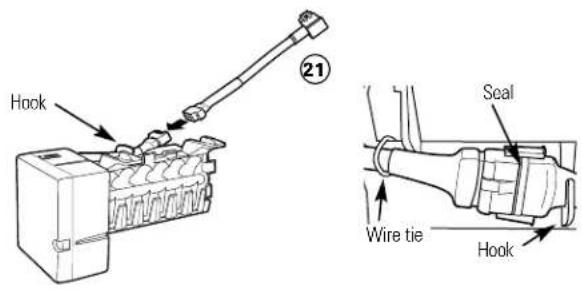
4 POWER CORD ADAPTER
There are two power cord adapters included with the kit; be sure to use the one specified in the Parts List on page 7. Plug the female end of the power cord adapter (20) onto the male terminals on the icemaker power cord. When connecting the adapter to the power cord, make sure the seal is in place between the connectors. Secure the power cord adapter to the icemaker by putting it into the hook at the back of the icemaker and attaching it to the icemaker with a wire tie (23).

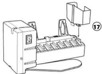
5 INSTALL THE ICEMAKER FILL CUP
Install the icemaker fill cup (side-mounted) (17) into the icemaker as shown.
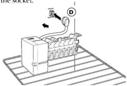
6 PLUG IN THE ICEMAKER
Place the icemaker in the freezer compartment on its side as shown. Insert the icemaker power cord plug (D) into the socket on the side wall, making sure the prongs and holes are matched. Press the plug firmly into the socket.
7 MOUNT THE ICEMAKER
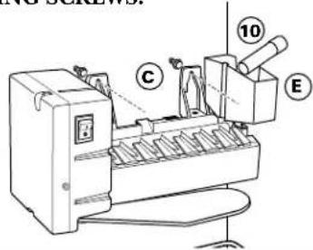
- Lift the icemaker so the fill tube extension (10) fits in the fill cup (E) opening. Hang the icemaker on the two mounting screws (C).
Make sure: - The power cord is still firmly in the socket.
- The fill tube extension (10) is still in the fill cup opening. (Check the rear of the refrigerator to make sure the fill tube has not been pushed out of the back of the refrigerator).
- The icemaker mounting screws are located in the uppermost position of the mounting slots. THEN SECURELY TIGHTEN THE ICEMAKER MOUNTING SCREWS.
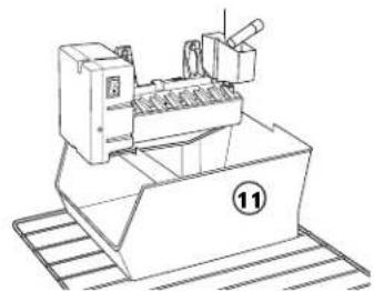
8 INSTALL THE ICE BUCKET
Put the ice bucket (11) directly under the icemaker (to the left and all the way to the rear of the shelf under the icemaker).
Make sure the icemaker power switch is set to 0 (off).
9 ATTACH WARRANTY LABEL
A label (9) is provided with this kit to record the date of installation for warranty purposes. Apply it to the back of the refrigerator.
10 KEEP THIS MANUAL
The warranty for the icemaker is printed in this manual. Keep this manual with your Refrigerator Owner's Manual.
The icemaker installation inside the freezer is now complete. Continue to the Water Valve Assembly section.
WATER VALVE ASSEMBLY INSTALLATION INSTRUCTIONS C
Are these the right instructions for your model? Follow the Installation Instructions indicated by the label on the back of the refrigerator—
BEFORE YOU BEGIN
Read each step thoroughly before proceeding.
CAUTION - Unplug the Refrigerator. To eliminate the danger of electric shock during installation, you must unplug the refrigerator from its electrical outlet.
TOOLS YOU WILL NEED
Flat blade and Phillips screwdrivers
Pliers
Sharp knife
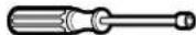
5/16"Nutdriver
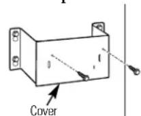
1REMOVE THE COVER
At the bottom rear of the refrigerator, remove the screw(s) holding the compressor compartment cover (if covered) and save for reinstallation later. Bend the cover back for access to the compartment.
2 ATTACH THE WATER VALVE
- Locate the female connector plug (A) which is attached to the cabinet with a wire tie. Remove the wire tie and discard it.
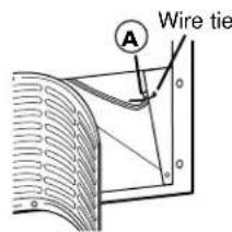
- Remove and discard the tape from the female connector (A) and plug onto the male terminals on the water valve (4). Either wire can go on either terminal.
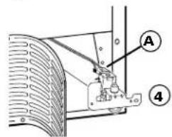
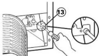
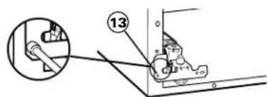
- Fasten the water valve to the cabinet edge hole using the hex-head screw (13) from the kit. DO NOT DRILL ANY ADDITIONAL HOLES.
- Check the plastic water line nut on the bottom of the water valve to be sure it is hand tight. DO NOT USE TOOLS.
3 INSTALL WATER LINE CLAMP
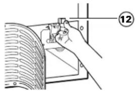
- Push the water line clamp (strain relief) (12) onto the lower flange of the cabinet back, directly in line with the water valve.
- The water line clamp is for the house water line. (See the Water Line Installation Instructions). It is not to be used for the tubing from the water valve up to the icemaker.
6 ATTACH THE PLASTIC WATER LINE
Fasten the plastic water line to the back of the cabinet with adhesive-backed fasteners (5), spacing the fasteners as shown to take up the slack in the line.
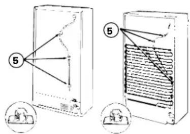
Adhesive-backed fasteners for plastic water line
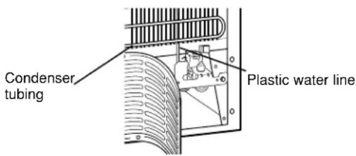
4 ROUTE THE PLASTIC WATER LINE
On models that have condenser tubing on the back of the cabinet, insert the plastic water line between the tubing and the back of the cabinet.
7 WATER VALVE INSTALLED
Refer to the Water Line Installation Instructions for connection to the home water supply. After water line installation is completed, set the icemaker power switch to 1 (on).
The icemaking cycle will not begin until the icemaker and freezer compartment reach operating temperature, then icemaking will begin automatically.
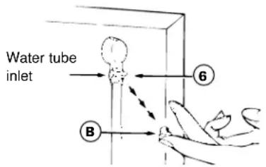
5 CONNECT THE WATER LINE
- Remove the small plastic cap (B) from the bottom of the water tube inlet located in the upper-right rear corner of the refrigerator.
- Squeeze the ends of the hose clamp (6) from the kit with pliers and slide the clamp over the water tube inlet.
- While still squeezing the clamp, insert the plastic water line into the inlet as far as it will go (approximately 1^ [25mm] ).
- Then slide the clamp downward to capture the plastic water line in place.
- Make sure the fill tube is aimed down.
ICEMAKER INSTALLATION INSTRUCTIONS K
Are these the right instructions for your model? Follow the Installation Instructions indicated by the label on the back of the refrigerator—K
BEFORE YOU BEGIN
Read each step thoroughly before proceeding.
- CAUTION - Unplug the Refrigerator. To eliminate the danger of electric shock during installation, you must unplug the refrigerator from its electrical outlet.
TOOLS YOU WILL NEED
Flat blade and Phillips screwdrivers
Pliers

Sharp knife
1 PREPARE FOR INSTALLATION
- Remove the upper outlet cover with a flat-blade screwdriver.
- If there is already an icemaker bracket (24) installed in the freezer, remove the two screws holding on the cover. Remove and discard the cover. Go to Step 5.
2REMOVE FILL HOLE PLUG
- Remove and discard the large white plug from the rear freezer wall. Pull out the gray insulation plug and remove any debris.
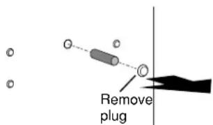
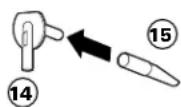
3INSTALL FILL TUBE
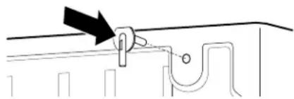
- Slide the insulated fill tube (15) onto the water tube inlet (14), making sure that the open side of the fill tube faces up.
- Go to the back of the refrigerator. On the tube side of the water tube inlet (14) there is an adhesive backing. Remove the adhesive backing and slide the tube into the hole near the top at the back of the refrigerator. Firmly press on the inlet to secure it to the refrigerator.
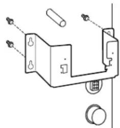
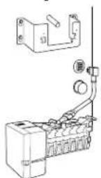
4 INSTALL MOUNTING BRACKET
- Remove the three small plug buttons on the rear wall of the freezer and replace them with three screws (25) supplied with the icemaker kit. Do not screw them all the way in. The screws should extend approximately 1/4'' (6 mm) out from the freezer wall.
Install the icemaker bracket (24) by hanging it from the three screws that were just installed. Tighten the three screws securely.
SET POWER SWITCH TO O (off)
Set the icemaker power switch to O (off).Leave the power switch in the O (off) position until the refrigerator is connected to the water supply to prevent premature operation.
6 POWER CORD ADAPTER
There are two power cord adapters included with the kit; be sure to use the one specified in the Parts List on page 7. Plug the female end of the power cord adapter (21) onto the male terminals on the icemaker power cord. When connecting the adapter to the power cord, make sure the seal is in place between the connectors. Secure the power cord adapter to the icemaker by putting it into the hook at the back of the icemaker and attaching it to the icemaker with a wire tie (23).
9 MOUNT THE ICEMAKER
- Lift the icemaker up and hang it on the icemaker bracket (24). Make sure the insulated fill tube (15) goes into the fill cup (18) opening. To secure the icemaker to the bracket (24), use two screws (16) and install as shown.
Make sure:
- The power cord is still firmly in the socket.
- The insulated fill tube (15) extends into the fill cup opening at the back of the icemaker. (Check the rear of the refrigerator to make sure that the
fill tube has not pushed out the back of the refrigerator).
The icemaker is secured to the bracket.
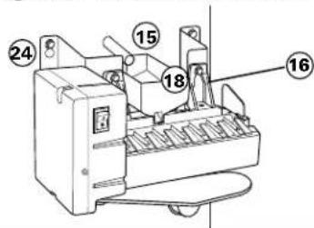
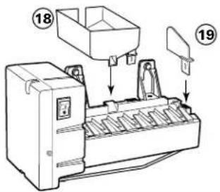
7INSTALL THE ICEMAKER FILL CUP AND INSERT
Install the icemaker fill cup (center-mounted) (18) and icemaker insert (19) into the icemaker as shown.
10INSTALL THE ICE BUCKET
Place the ice bucket (11) under the icemaker.
Make sure the icemaker power switch is set to 0 (off).
8 PLUG IN THE ICEMAKER
Holding the icemaker in place, insert the power cord plug into the socket, making sure that the prongs and holes are matched. Press the plug firmly into the socket. Lock the plug in place by clipping the restraints onto each side of the plug. Make sure the restraints click into place.
ATTACH WARRANTY LABEL
A label (9) is provided with this kit to record the date of installation for warranty purposes. Apply it to the back of the refrigerator.
12 KEEP THIS MANUAL
The warranty for the icemaker is printed in this manual. Keep this manual with your Refrigerator Owner's Manual.
The icemaker installation inside the freezer is now complete. Continue to the Installing the Water Valve Assembly section.
WATER VALVE ASSEMBLY INSTALLATION INSTRUCTIONS K
Are these the right instructions for your model? Follow the Installation Instructions indicated by the label on the back of the refrigerator—K
BEFORE YOU BEGIN
Read each step thoroughly before proceeding.
CAUTION - Unplug the Refrigerator. To eliminate the danger of electric shock during installation, you must unplug the refrigerator from its electrical outlet.
TOOLS YOU WILL NEED

Flat blade and Phillips screwdrivers
Pliers
Sharp knife
1/4" and 5/16" Nutdrivers, or adjustable wrench
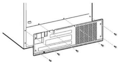
1REMOVE THE COVER
Use a nutdriver or an adjustable wrench to remove the compressor compartment access cover. This requires removing six screws which attach the cover to the back of the refrigerator case.
Be sure to save the screws as the access cover must be reinstalled later to ensure your refrigerator will function properly.
2 ATTACH THE WATER VALVE
- Locate the 3-pin male connector plug (C). Plug the water valve wire adapter (22) onto the male connector plug, then plug it onto the male terminals on the water valve (4). Either wire can go on either water valve terminal.
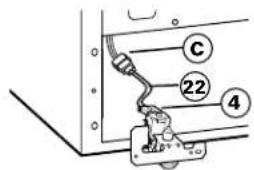
- Fasten the water valve to the cabinet using the hex-head screw (13) from the kit.
3INSTALL WATER LINE CLAMP
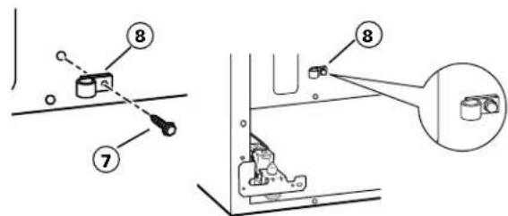
- Attach the water line clamp (strain relief) (8) to the refrigerator. Drive the screw (7) from the kit through the clamp (8) and into the small hole at the back of the cabinet.
- The water line clamp is for the house water line (see the Water Line Installation Instructions). It is not to be used for the tubing from the water valve up to the icemaker.
4 CONNECT THE WATER LINE
- Make sure there is enough plastic water line to extend from the water valve to well into the water tube inlet (14). Cut off any excess tubing.
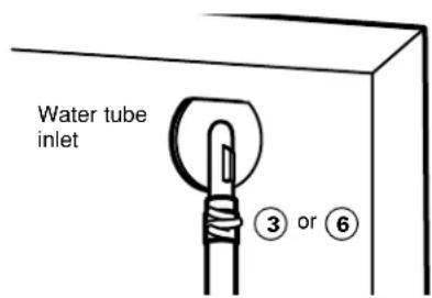
- Squeeze the ends of the hose clamp (3) or (6) from the kit with pliers and slide the clamp over the water tube inlet. (Use the black clamp (3) with the black water tube inlet, use the other clamp (6) with the other water tube inlet.)
- While still squeezing the clamp, insert the plastic water line into the inlet as far as it will go (approximately 1^ [25mm] ).
- Then slide the clamp downward to capture the plastic water line in place.
- Make sure the fill tube is aimed down.
5 ROUTE AND ATTACH PLASTIC WATER LINE
- Route the plastic water line along the back of the refrigerator to the water tube inlet.
- Use the three adhesive backed fasteners (5) to secure the plastic water line to the case back.
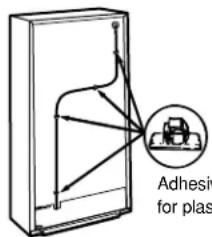
Adhesive-backed fasteners for plastic water line
6 WATER VALVE INSTALLED
Refer to the Water Line Installation Instructions for connection to the home water supply. After water line installation is completed, set the icemaker power switch to I (on).
The icemaking cycle will not begin until the icemaker and freezer compartment reach operating temperature, then icemaking will begin automatically.
INSTALLING THE WATER LINE
BEFORE YOU BEGIN
Recommended copper water supply kits are WX8X2, WX8X3 or WX8X4, depending on the amount of tubing you need. Approved plastic water supply lines are GE SmartConnect™ Refrigerator Tubing (WX08X10002, WX08X10006, WX08X10015 and WX08X10025).
When connecting your refrigerator to a GE Reverse Osmosis Water System, the only approved installation is with a GE RVKit. For other reverse osmosis water systems, follow the manufacturer's recommendations.
If the water supply to the refrigerator is from a Reverse Osmosis Water Filtration System AND the refrigerator also has a water filter, use the refrigerator's filter bypass plug. Using the refrigerator's water filtration cartridge in conjunction with the RO filter can result in hollow ice cubes and slower water flow from the water dispenser.
This water line installation is not warranted by the refrigerator or icemaker manufacturer. Follow these instructions carefully to minimize the risk of expensive water damage.
Water hammer (water banging in the pipes) in house plumbing can cause damage to refrigerator parts and lead to water leakage or flooding. Call a qualified plumber to correct water hammer before installing the water supply line to the refrigerator.
To prevent burns and product damage, do not hook up the water line to the hot water line.
If you use your refrigerator before connecting the water line, make sure the icemaker power switch is in the 0 (off) position.
Do not install the icemaker tubing in areas where temperatures fall below freezing.
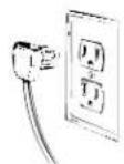
When using any electrical device (such as a power drill) during installation, be sure the device is double insulated or grounded in a manner to prevent the hazard of electric shock, or is battery powered.
All installations must be in accordance with local plumbing code requirements.
WHAT YOU WILL NEED
- Copper or GE SmartConnect™ Refrigerator Tubing kit, 1/4'' outer diameter to connect the refrigerator to the water supply. If using copper, be sure both ends of the tubing are cut square.
To determine how much tubing you need: measure the distance from the water valve on the back of the refrigerator to the water supply pipe. Then add 8 feet (2.4m) .Be sure there is sufficient extra tubing (about 8 feet [2.4m] coiled into 3 turns of about 10^ [25 cm] diameter) to allow the refrigerator to move out from the wall after installation.
GE SmartConnect™ Refrigerator Tubing Kits are available in the following lengths:
2^(6m) -WX08X10002
6^(1.8m) - WX08X10006
15^(4.6m) -WX08X10015
25^(7.6m) -WX08X10025
Be sure that the kit you select allows at least 8 feet (2.4m) as described above.
NOTE: The only GE approved plastic tubing is that supplied in GE SmartConnect™ Refrigerator Tubing kits. Do not use any other plastic water supply line because the line is under pressure at all times. Certain types of plastic will crack or rupture with age and cause water damage to your home.
-
A GE water supply kit (containing tubing, shutoff valve and fittings listed below) is available at extra cost from your dealer or from Parts and Accessories, 800-626-2002.
-
A cold water supply. The water pressure must be between 20 and 120 p.s.i. (1.4-8.2 bar) on models without a water filter and between 40 and 120 p.s.i. (2.8-8.2 bar) on models with a water filter.
WHAT YOU WILL NEED (CONT.)
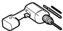
- Power drill.
- 1 / 2'' or adjustable wrench.
- Straight and Phillips blade screwdriver.
- Two 1/4'' outer diameter compression nuts and 2 ferrules (sleeves)—to connect the copper tubing to the shutoff valve and the refrigerator water valve.
OR
- If you are using a GE SmartConnect™ Refrigerator Tubing kit, the necessary fittings are preassembled to the tubing.
- If your existing copper water line has a flared fitting at the end, you will need an adapter (available at plumbing supply stores) to connect the water line to the refrigerator OR you can cut off the flared fitting with a tube cutter and then use a compression fitting. Do not cut formed end from GE SmartConnect™ Refrigerator tubing.
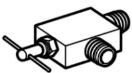
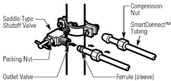
- Shutoff valve to connect to the cold water line. The shutoff valve should have a water inlet with a minimum inside diameter of 5/32'' at the point of connection to the COLD WATER LINE. Saddle-type shutoff valves are included in many water supply kits. Before purchasing, make sure a saddle-type valve complies with your local plumbing codes.
Install the shutoff valve on the nearest frequently used drinking water line.
1 SHUT OFF THE MAIN WATER SUPPLY
Turn on the nearest faucet long enough to clear the line of water.
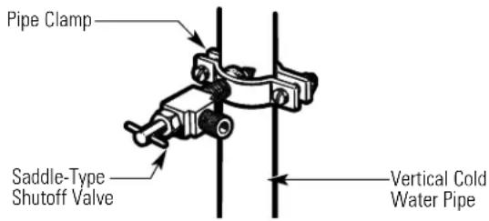
2 CHOOSE THE VALVE LOCATION
Choose a location for the valve that is easily accessible. It is best to connect into the side of a vertical water pipe. When it is necessary to connect into a horizontal water pipe, make the connection to the top or side, rather than at the bottom, to avoid drawing off any sediment from the water pipe.
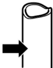
3 DRILL THE HOLE FOR THE VALVE
Drill a 1/4'' hole in the water pipe (even if using a self-piercing valve) using a sharp bit. Remove any burrs resulting from drilling the hole in the pipe. Take care not to allow water to drain into the drill. Failure to drill a 1/4'' hole may result in reduced ice production or smaller cubes.
INSTALLING THE WATER LINE (CONT.)
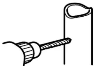
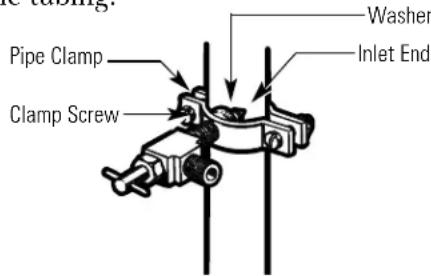
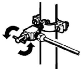
4 FASTEN THE SHUTOFF VALVE
Fasten the shutoff valve to the cold water pipe with the pipe clamp.
NOTE: Commonwealth of Massachusetts Plumbing Codes 248CMR shall be adhered to. Saddle valves are illegal and use is not permitted in Massachusetts. Consult with your licensed plumber.
5 TIGHTEN THE PIPE CLAMP
Tighten the clamp screws until the sealing washer begins to swell.
NOTE: Do not overtighten or you may crush the tubing.
6 ROUTE THE TUBING
Route the tubing between the cold water line and the refrigerator.
Route the tubing through a hole drilled in the wall or floor (behind the refrigerator or adjacent base cabinet) as close to the wall as possible.
NOTE: Be sure there is sufficient extra tubing (about 8 feet [244 cm] coiled into 3 turns of about 10^ [25cm] diameter) to allow the refrigerator to move out from the wall after installation.
7 CONNECT THE TUBING TO THE VALVE
Place the compression nut and ferrule (sleeve) for copper tubing onto the end of the tubing and connect it to the shutoff valve.
Make sure the tubing is fully inserted into the valve. Tighten the compression nut securely.
For plastic tubing from a GE SmartConnect™ Refrigerator Tubing kit, insert the molded end of the tubing into the shutoff valve and tighten compression nut until it is hand tight, then tighten one additional turn with a wrench. Overtightening may cause leaks.
NOTE: Commonwealth of Massachusetts Plumbing Codes 248CMR shall be adhered to. Saddle valves are illegal and use is not permitted in Massachusetts. Consult with your licensed plumber.
8 FLUSH OUT THE TUBING
Turn the main water supply on and flush out the tubing until the water is clear.
Shut the water off at the water valve after about one quart (1 liter) of water has been flushed through the tubing.

9 CONNECT THE TUBING TO THE REFRIGERATOR
NOTES:
- Before making the connection to the refrigerator, be sure the refrigerator power cord is not plugged into the wall outlet.
- If your refrigerator does not have a water filter we recommend installing one. If your water supply has sand or particles that could clog the screen of the refrigerator's water valve. Install it in the water line near the refrigerator. If using GE SmartConnect™ Refrigerator Tubing kit, you will need an additional tube (WX08X10002) to connect the filter. Do not cut plastic tube to install filter.
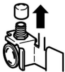
Remove the plastic flexible cap from the water valve (refrigerator connection).
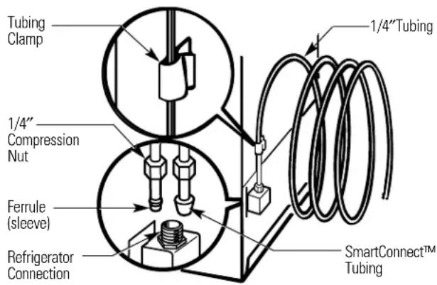
Place the compression nut and ferrule (sleeve) onto the end of the tubing as shown. On GE
SmartConnect Refrigerator
Tubing kit, the nuts are already assembled to the tubing.
Insert the end of the tubing into the water valve (refrigerator connection) as far as possible. While holding the tubing, tighten the fitting.
For plastic tubing from a GE SmartConnect Refrigerator Tubing kit, insert the molded end of the tubing into the refrigerator connection and tighten compression nut until it is hand tight, then tighten one additional turn with a wrench. Overtightening may cause leaks.
Fasten the tubing into the clamp provided to hold it in a vertical position. You may need to pry open the clamp.
10 TURN THE WATER ON AT THE SHUTOFF VALVE
Tighten any connections that lcek.
Reattach the compressor compartment access cover.
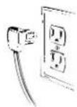
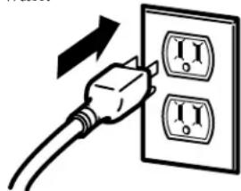
11 PLUG IN THE REFRIGERATOR
Arrange the coil of tubing so that it does not vibrate against the back of the refrigerator or against the wall. Push the refrigerator back to the wall.
12 START THE ICEMAKER
Set the icemaker power switch to the I (on) position. The icemaker will not begin to operate until it reaches its operating temperature of 15^ (-9^) or below. It will then begin operation automatically if the icemaker power switch is in the I (on) position.
NOTE: In lower water pressure conditions, the water valve may turn on up to 3 times to deliver enough water to the icemaker.
All warranty service provided by our Factory Service Centers, or an authorized Customer Care technician. To schedule service, on-line, 24 hours a day, contact us at www.GEApliances.com, or call 800-GE-CARES. In Canada, call 1-800-361-3400.
Staple your receipt here. Proof of the original purchase date is needed to obtain service under the warranty.
For The Period Of: We Will Replace:
One Year
From the date of the
Any part of the icemaker which fails due to a defect in materials or workmanship.
During this full one-year warranty, GE will provide, free of charge, replacement parts
original purchase for any defective part in your icemaker kit.
What Is Not Covered (for customers in the United States):
Service trips to your home to teach you how to use the product.
Improper installation.
You are responsible for providing adequate electrical, plumbing, and other connecting facilities, including the water line to the icemaker and the water line installation.
Failure of the product if it is abused, misused, or used for other than the intended purpose or used commercially.
Replacement of house fuses or resetting of circuit breakers.
Damage to the product caused by accident, fire, floods or acts of God.
Incidental or consequential damage caused by possible defects with this appliance.
This warranty is extended to the original purchaser and any succeeding owner for products purchased for home use within the USA. In Alaska, the warranty excludes the cost of shipping or service calls to your home.
Some states do not allow the exclusion or limitation of incidental or consequential damages. This warranty gives you specific legal rights, and you may also have other rights which vary from state to state. To know what your legal rights are, consult your local or state consumer affairs office or your state's Attorney General.
Warrantor: General Electric Company. Louisville, KY 40225
What Is Not Covered (for customers in Canada):
Service trips to your home to teach you how to use the product.
Read your Owner's Manual. If you then have any questions about operating the product, please contact your dealer or our Consumer Relations office at:
Manager, Consumer Relations
Camco Inc.
1 Factory Lane, Suite 310
Moncton, N.B.
E1C 9M3
Improper installation.
If you have an installation problem, contact your dealer or installer. You are responsible for providing adequate electrical, exhausting and other connecting facilities.
Replacement of house fuses or resetting of circuit breakers.
Failure of the product if it is misused, or used for other than the intended purpose or used commercially.
Damage to product caused by accident, fire, floods or acts of God.
WARRANTOR IS NOT RESPONSIBLE FOR CONSEQUENTIAL DAMAGES.
Warrantor: CAMCO INC.
10 CONSERVEZ CE MANUEL
ENLEVEZ LE COUVERCLE
ENLEVEZ LE COUVERCLE
Garant: General Electric Company, Louisville, KY 40225
7 CONECTE LA TUBERIA A LA VALVULA
Garante: General Electric Company. Louisville, KY 40225
Manager, Consumer Relations
Camco Inc.
1FactoryLane,Suite310
Moncton, N.B.
E1C 9M3
In the U.S.: www.GEApliances.com
Have a question or need assistance with your appliance? Try the GE Appliances Website 24 hours a day, any day of the year! For greater convenience and faster service, you can now download Owner's Manuals, order parts, catalogs, or even schedule service on-line. You can also "Ask Our Team of Experts" your questions, and so much more... In Canada: www.geappliances.ca
Schedule Service
In the U.S.: www.GEApliances.com
Expert GE repair service is only one step away from your door. Get on-line and schedule your service at your convenience 24 hours any day of the year! Or call 800-GE-CARES (800-432-2737) during normal business hours. In Canada, call 1-800-361-3400
Real Life Design Studio
In the U.S.: www.GEApliances.com
GE supports the Universal Design concept—products, services and environments that can be used by people of all ages, sizes and capabilities. We recognize the need to design for a wide range of physical and mental abilities and impairments. For details of GE's Universal Design applications, including kitchen design ideas for people with disabilities, check out our Website today. For the hearing impaired, please call 800-TDD-GEAC (800-833-4322).
In Canada, contact: Manager, Consumer Relations, Camco, Inc.
Suite 310, 1 Factory Lane
Moncton, N.B. E1C 9M3
Extended Warranties
In the U.S.: www.GEApliances.com
Purchase a GE extended warranty and learn about special discounts that are available while your warranty is still in effect. You can purchase it on-line anytime, or call 800-626-2224 during normal business hours. GE Consumer Home Services will still be there after your warranty expires. In Canada, call 1-888-261-2133
Parts and Accessories
In the U.S.: www.GEApliances.com
Individuals qualified to service their own appliances can have parts or accessories sent directly to their homes (VISA, MasterCard and Discover cards are accepted). Order on-line today, 24 hours every day or by phone at 800-626-2002 during normal business hours.
Instructions contained in this manual cover procedures to be performed by any user. Other servicing generally should be referred to qualified service personnel. Caution must be exercised, since improper servicing may cause unsafe operation.
Customers in Canada should consult the yellow pages for the nearest Camco service center, or call 1-888-261-3055.

Contact Us
In the U.S.: www.GEApliances.com
If you are not satisfied with the service you receive from GF, contact us on our Website with all the details including your phone number, or write to: General Manager, Customer Relations
GE Appliances, Appliance Park
Louisville, KY 40225
In Canada: www.geappliances.ca, or write to: Director, Consumer Relations, Camco, Inc.
Suite 310, 1 Factory Lane
Moncton, N.B. E1C 9M3
Register Your Appliance
In the U.S.: www.GEApliances.com
Register your new appliance on-line—at your convenience! Timely product registration will allow for enhanced communication and prompt service under the terms of your warranty, should the need arise. You may also mail in the pre-printed registration card included in the packing material, or detach and use the form in this Owner's Manual. In Canada: www.geappliances.ca
- Icemaker Accessory Kit
- Installation Instructions
- Consumer Support
- Which instructions should you follow?
- Owner's Manual and Installation Instructions
- Kit IM-5SS
- Machine à glaçons
- SAFETY PRECAUTIONS
- FOR YOUR SAFETY:
- READ AND FOLLOW THIS SAFETY INFORMATION CAREFULLY. READ AND SAVE THESE INSTRUCTIONS
- Automatic Icemaker
- Preparing for Vacation
- When you should set the icemaker power switch to O (off)
- Normal sounds you may hear
- Before you call for service...
- Installation IM-5SS Instructions Icemaker Kit
- BEFORE YOU BEGIN
- ARE YOU REPLACING AN ICEMAKER WITH THIS KIT?
- DAMAGE - SHIPMENT/INSTALLATION
- CONTENTS OF KIT IM-5SS
- ICEMAKER INSTALLATION INSTRUCTIONS C
- TOOLS YOU WILL NEED
- PREPARE FOR INSTALLATION
- INSTALL FILL TUBE EXTENSION
- SET POWER SWITCH TO O (off)
- POWER CORD ADAPTER
- INSTALL THE ICEMAKER FILL CUP
- PLUG IN THE ICEMAKER
- MOUNT THE ICEMAKER
- INSTALL THE ICE BUCKET
- ATTACH WARRANTY LABEL
- KEEP THIS MANUAL
- WATER VALVE ASSEMBLY INSTALLATION INSTRUCTIONS C
- 1REMOVE THE COVER
- ATTACH THE WATER VALVE
- INSTALL WATER LINE CLAMP
- ATTACH THE PLASTIC WATER LINE
- ROUTE THE PLASTIC WATER LINE
- WATER VALVE INSTALLED
- CONNECT THE WATER LINE
- ICEMAKER INSTALLATION INSTRUCTIONS K
- 2REMOVE FILL HOLE PLUG
- 3INSTALL FILL TUBE
- INSTALL MOUNTING BRACKET
- SET POWER SWITCH TO O (off)
- POWER CORD ADAPTER
- MOUNT THE ICEMAKER
- Make sure:
- 7INSTALL THE ICEMAKER FILL CUP AND INSERT
- 10INSTALL THE ICE BUCKET
- PLUG IN THE ICEMAKER
- ATTACH WARRANTY LABEL
- KEEP THIS MANUAL
- WATER VALVE ASSEMBLY INSTALLATION INSTRUCTIONS K
- 3INSTALL WATER LINE CLAMP
- CONNECT THE WATER LINE
- ROUTE AND ATTACH PLASTIC WATER LINE
- WATER VALVE INSTALLED
- INSTALLING THE WATER LINE
- WHAT YOU WILL NEED
- WHAT YOU WILL NEED (CONT.)
- OR
- SHUT OFF THE MAIN WATER SUPPLY
- CHOOSE THE VALVE LOCATION
- DRILL THE HOLE FOR THE VALVE
- INSTALLING THE WATER LINE (CONT.)
- FASTEN THE SHUTOFF VALVE
- TIGHTEN THE PIPE CLAMP
- ROUTE THE TUBING
- CONNECT THE TUBING TO THE VALVE
- FLUSH OUT THE TUBING
- CONNECT THE TUBING TO THE REFRIGERATOR
- NOTES:
- TURN THE WATER ON AT THE SHUTOFF VALVE
- PLUG IN THE REFRIGERATOR
- START THE ICEMAKER
- For The Period Of: We Will Replace:
- One Year
- What Is Not Covered (for customers in the United States):
- What Is Not Covered (for customers in Canada):
- CONSERVEZ CE MANUEL
- ENLEVEZ LE COUVERCLE
- CONECTE LA TUBERIA A LA VALVULA
- Schedule Service
- Real Life Design Studio
- Extended Warranties
- Parts and Accessories
- Contact Us
- Register Your Appliance
Brand : GE
Model : IM5SS
Category : Ice Maker